Makita BTP131 User manual

1
GB Cordless 4 Mode Impact Driver INSTRUCTION MANUAL
S
Batteridriven slagskruvdragare med 4 lägen
BRUKSANVISNING
N
Batteridrevet slagskrutrekker med 4 modus
BRUKSANVISNING
FIN
Akkukäyttöinen 4-moodinen iskuväännin
KÄYTTÖOHJE
LV
Bezvada 4 režīmu triecienskrūvgriezis
LIETOŠANAS INSTRUKCIJA
LT
Belaidis 4 režimųsmūginis suktuvas
NAUDOJIMO INSTRUKCIJA
EE
Juhtmeta 4-režiimne löökkruvikeeraja
KASUTUSJUHEND
RUS
Аккумуляторный 4 режимный ударный шуруповерт
РУКОВОДСТВО ПО ЭКСПЛУАТАЦИИ
BTP131
BTP141

2
1
2
3
1 012233
1
2 012128
1
3 012237
1
4 012231
1
2
5 012249
1
AB
6 012238
1
7 012240
12
3
8 012239
1
9 012241
10 004521
1
2
11 012234
12
3
12 012235
1
2
3
13 012236 14 012242

3
ENGLISH (Original instructions)
Explanation of general view
1-1. Red indicator
1-2. Button
1-3. Battery cartridge
2-1. Star marking
3-1. Switch trigger
4-1. Lamp
5-1. LED display
5-2. Lamp button
6-1. Reversing switch lever
7-1. Speed change lever
8-1. Mode mark
8-2. Action mode changing ring
8-3. Arrow
9-1. Battery capacity
11-1. Bit
11-2. Sleeve
12-1. Bit
12-2. Bit-piece
12-3. Sleeve
13-1. Groove
13-2. Hook
13-3. Screw
SPECIFICATIONS
Model BTP131 BTP141
Machine screw 4 mm - 8 mm
Standard bolt 5 mm - 14 mm
Fastening
Capacities High tensile bolt 5 mm - 12 mm
No load speed (min
-1
) (Soft / Medium / Hard)
0 - 1,400 / 0 - 2,200 / 0 - 2,800 0 - 1,300 / 0 - 2,200 / 0 - 2,700
Impact driver
mode
Impacts per minute (Soft / Medium / Hard) 0 - 1,200 / 0 - 2,400 / 0 - 3,200
Low (1) / High (2)
No load speed (min-1) 0 - 700 / 0 - 2,800 0 - 700 / 0 - 2,700
Blows per minute (min-1) 0 - 8,400 / 0 - 32,400
Hammer drill mode
Drilling Capacities / Concrete 8 mm
Steel 10 mm / 6.5 mm
Wood 21 mm / 12 mm
Drill mode Drilling Capacities
No load speed (min
-1
)
0 - 700 / 0 - 2,800 0 - 700 / 0 - 2,700
Machine screw 3.5 mm - 6 mm / 4 mm - 6 mm
Self drilling screw 4 mm, 5 mm / 4 mm (Thickness 3.2 mm max.)
Screwdriver mode Fastening
Capacities No load speed
(min-1)
0 - 300 / 0 - 1,100 (depends on torque setting)
0 - 600 / 0 - 2,300 (P mode)
Net weight (with battery cartridge) 1.5 kg ( with battery BL1415)
1.7 kg ( with battery BL1430)
1.6 kg ( with battery BL1815)
1.8 kg ( with battery BL1830)
Rated voltage D.C.14.4 V D.C.18 V
• Due to our continuing programme of research and development, the specifications herein are subject to change without notice.
• Specifications and battery cartridge may differ from country to country.
• Weight, with battery cartridge, according to EPTA-Procedure 01/2003
ENE033-1
Intended use
The tool is intended for screw driving in wood, metal and
plastic.
ENG905-1
Noise
The typical A-weighted noise level determined according
to EN60745:
Model BTP131
Sound pressure level (LpA) : 85 dB(A)
Sound power level (LWA) : 96 dB(A)
Uncertainty (K) : 3 dB(A)
Model BTP141
Sound pressure level (LpA) : 85 dB(A)
Sound power level (LWA) : 96 dB(A)
Uncertainty (K) : 3 dB(A)
Wear ear protection
ENG900-1
Vibration
The vibration total value (tri-axial vector sum) determined
according to EN60745:
Model BTP131
Work mode: impact drilling into concrete
Vibration emission (ah,ID) : 13 m/s2
Uncertainty (K) : 1.5 m/s2
Work mode : impact tightening of fasteners of the
maximum capacity of the tool
Vibration emission (ah) : 8.5 m/s2
Uncertainty (K) : 2 m/s2

4
Work mode: drilling into metal
Vibration emission (ah,D) : 2.5 m/s2or less
Uncertainty (K) : 1.5 m/s2
Model BTP141
Work mode: impact drilling into concrete
Vibration emission (ah,ID) : 13 m/s2
Uncertainty (K) : 1.5 m/s2
Work mode : impact tightening of fasteners of the
maximum capacity of the tool
Vibration emission (ah) : 10.5 m/s2
Uncertainty (K) : 1.5 m/s2
Work mode: drilling into metal
Vibration emission (ah,D) : 2.5 m/s2or less
Uncertainty (K) : 1.5 m/s2
ENG901-1
• The declared vibration emission value has been
measured in accordance with the standard test
method and may be used for comparing one tool
with another.
• The declared vibration emission value may also be
used in a preliminary assessment of exposure.
WARNING:
• The vibration emission during actual use of the
power tool can differ from the declared emission
value depending on the ways in which the tool is
used.
• Be sure to identify safety measures to protect the
operator that are based on an estimation of
exposure in the actual conditions of use (taking
account of all parts of the operating cycle such as
the times when the tool is switched off and when it
is running idle in addition to the trigger time).
ENH101-15
For European countries only
EC Declaration of Conformity
We Makita Corporation as the responsible
manufacturer declare that the following Makita
machine(s):
Designation of Machine:
Cordless 4 Mode Impact Driver
Model No./ Type: BTP131, BTP141
are of series production and
Conforms to the following European Directives:
2006/42/EC
And are manufactured in accordance with the following
standards or standardised documents:
EN60745
The technical documentation is kept by our authorised
representative in Europe who is:
Makita International Europe Ltd.
Michigan Drive, Tongwell,
Milton Keynes, Bucks MK15 8JD, England
14.4.2011
000230
Tomoyasu Kato
Director
Makita Corporation
3-11-8, Sumiyoshi-cho,
Anjo, Aichi, 446-8502, JAPAN
GEA010-1
General Power Tool Safety
Warnings
WARNING Read all safety warnings and all
instructions. Failure to follow the warnings and
instructions may result in electric shock, fire and/or
serious injury.
Save all warnings and instructions for
future reference.
GEB078-2
CORDLESS 4 MODE IMPACT
DRIVER SAFETY WARNINGS
1. Wear ear protectors when impact drilling.
Exposure to noise can cause hearing loss.
2. Use auxiliary handle(s), if supplied with the
tool. Loss of control can cause personal injury.
3. Hold power tool by insulated gripping
surfaces, when performing an operation
where the fastener may contact hidden wiring.
Fasteners contacting a "live" wire may make
exposed metal parts of the power tool "live" and
could give the operator an electric shock.
4.
Hold power tool by insulated gripping surfaces,
when performing an operation where the
cutting accessory may contact hidden wiring.
Cutting accessory contacting a "live" wire may
make exposed metal parts of the power tool "live"
and could give the operator an electric shock.
5. Always be sure you have a firm footing.
Be sure no one is below when using the tool in
high locations.
6. Hold the tool firmly.
7. Keep hands away from rotating parts.
8. Do not leave the tool running. Operate the tool
only when hand-held.
9. Do not touch the bit or the workpiece
immediately after operation; they may be
extremely hot and could burn your skin.
10. Some material contains chemicals which may
be toxic. Take caution to prevent dust
inhalation and skin contact. Follow material
supplier safety data.
SAVE THESE INSTRUCTIONS.

5
WARNING:
DO NOT let comfort or familiarity with product
(gained from repeated use) replace strict adherence
to safety rules for the subject product. MISUSE or
failure to follow the safety rules stated in this
instruction manual may cause serious personal
injury.
ENC007-7
IMPORTANT SAFETY
INSTRUCTIONS
FOR BATTERY CARTRIDGE
1. Before using battery cartridge, read all
instructions and cautionary markings on (1)
battery charger, (2) battery, and (3) product
using battery.
2. Do not disassemble battery cartridge.
3. If operating time has become excessively
shorter, stop operating immediately. It may
result in a risk of overheating, possible burns
and even an explosion.
4. If electrolyte gets into your eyes, rinse them
out with clear water and seek medical
attention right away. It may result in loss of
your eyesight.
5. Do not short the battery cartridge:
(1) Do not touch the terminals with any
conductive material.
(2) Avoid storing battery cartridge in a
container with other metal objects such as
nails, coins, etc.
(3) Do not expose battery cartridge to water
or rain.
A battery short can cause a large current flow,
overheating, possible burns and even a
breakdown.
6. Do not store the tool and battery cartridge in
locations where the temperature may reach or
exceed 50 ゚C (122 ゚F).
7.
Do not incinerate the battery cartridge even if it
is severely damaged or is completely worn out.
The battery cartridge can explode in a fire.
8. Be careful not to drop or strike battery.
9. Do not use a damaged battery.
SAVE THESE INSTRUCTIONS.
Tips for maintaining maximum battery life
1. Charge the battery cartridge before
completely discharged.
Always stop tool operation and charge the
battery cartridge when you notice less tool
power.
2.
Never recharge a fully charged battery
cartridge.
Overcharging shortens the battery service life.
3. Charge the battery cartridge with room
temperature at 10 ゚C - 40 ゚C (50 ゚F - 104 ゚F).
Let a hot battery cartridge cool down before
charging it.
4. Charge the battery cartridge once in every six
months if you do not use it for a long period of
time.
FUNCTIONAL DESCRIPTION
CAUTION:
• Always be sure that the tool is switched off and the
battery cartridge is removed before adjusting or
checking function on the tool.
Installing or removing battery cartridge
Fig.1
• Always switch off the tool before installing or
removing of the battery cartridge.
•
To remove the battery cartridge, slide it from the tool
while sliding the button on the front of the cartridge.
• To install the battery cartridge, align the tongue on
the battery cartridge with the groove in the housing
and slip it into place. Always insert it all the way
until it locks in place with a little click. If you can see
the red indicator on the upper side of the button, it is
not locked completely. Install it fully until the red
indicator cannot be seen. If not, it may accidentally
fall out of the tool, causing injury to you or someone
around you.
Do not use force when installing the battery cartridge. If
the cartridge does not slide in easily, it is not being
inserted correctly.
Battery protection system (Lithium-ion
battery with star marking)
Fig.2
Lithium-ion batteries with a star marking are equipped
with a protection system. This system automatically cuts
off power to the tool to extend battery life.
The tool will automatically stop during operation if the tool
and/or battery are placed under one of the following
conditions:
• Overloaded:
The tool is operated in a manner that causes
it to draw an abnormally high current.
In this situation, release the trigger switch on
the tool and stop the application that caused
the tool to become overloaded. Then pull the
trigger switch again to restart.
If the tool does not start, the battery is
overheated. In this situation, let the battery
cool before pulling the trigger switch again.
• Low battery voltage:
The remaining battery capacity is too low and
the tool will not operate. In this situation,
remove and recharge the battery.

6
Switch action
Fig.3
CAUTION:
• Before installing the battery cartridge into the tool,
always check to see that the switch trigger actuates
properly and returns to the "OFF" position when
released.
To start the tool, simply pull the switch trigger. The tool
speed is increased by increasing pressure on the switch
trigger. Release the switch trigger to stop.
NOTE:
• The tool will stop three minutes after pulling the
switch trigger.
Lighting up the front lamp
CAUTION:
• Do not look in the lamp or see the source of lamp
directly.
Fig.4
Fig.5
Every time the lamp button on the LED display is
pressed, the lamp status is alternatively changed from
the ON to the OFF and from the OFF to the ON.
With the lamp button in the ON status, pull the switch
trigger to turn on the lamp. To turn off, release it and the
lamp goes out approximately 10 seconds after releasing.
With the lamp button in the OFF status, even if the trigger
is pulled, the lamp will not light on.
NOTE:
• To make sure the status of lamp, pull the trigger.
When the lamp lights up by pulling the switch
trigger, the lamp switch is in the ON status. When
the lamp does not come on, the lamp switch is in
the OFF status.
• During the operation of switch trigger, the lamp
status cannot be changed.
• For approximately 10 seconds after releasing the
switch trigger, the lamp status can be switched.
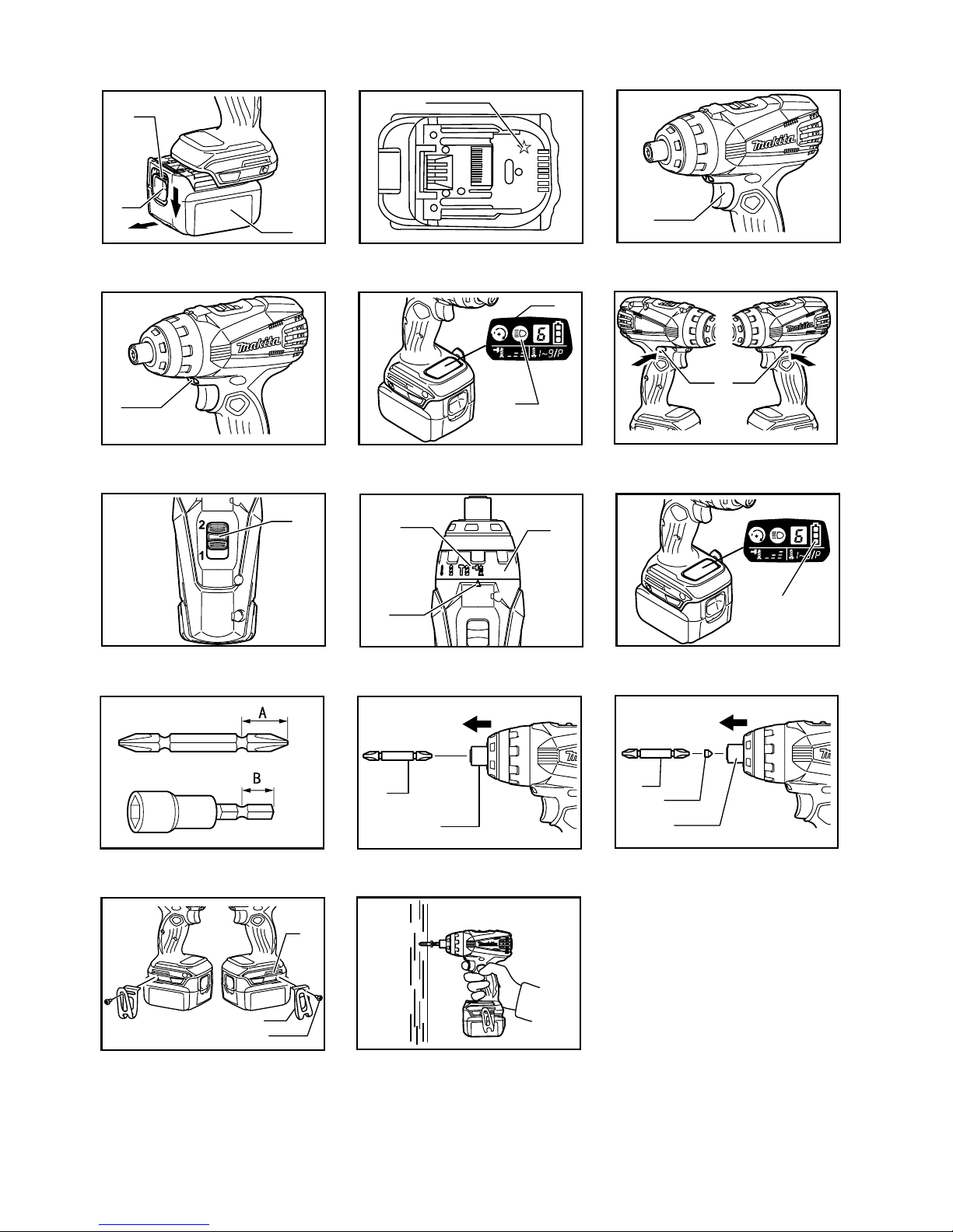
Reversing switch action
Fig.6
This tool has a reversing switch to change the direction of
rotation. Depress the reversing switch lever from the A
side for clockwise rotation or from the B side for
counterclockwise rotation.
When the reversing switch lever is in the neutral position,
the switch trigger cannot be pulled.
CAUTION:
• Always check the direction of rotation before
operation.
• Use the reversing switch only after the tool comes
to a complete stop. Changing the direction of
rotation before the tool stops may damage the tool.
• When not operating the tool, always set the
reversing switch lever to the neutral position.
Speed change
Fig.7
NOTICE:
• Always set the speed change lever fully to the
correct position. If you operate the tool with the
speed change lever positioned halfway between
the "1" side and "2" side, the tool may be damaged.
• Do not use the speed change lever while the tool is
running. The tool may be damaged.
• Do not force the lever to "1" side with impact driver
mode. The tool may be damaged.
To change the speed, first switch off the tool and then
slide the speed change lever to the "2" side for high
speed or "1" side for low speed. Be sure that the speed
change lever is set to the correct position before
operation. Use the right speed for your job.
When turning the action mode changing ring to impact
driver mode, set the speed change lever to the "2" side.
Selecting the action mode
Fig.8
This tool employs an action mode changing ring. Select
one of the 4 modes suitable for your work need by turning
this ring.
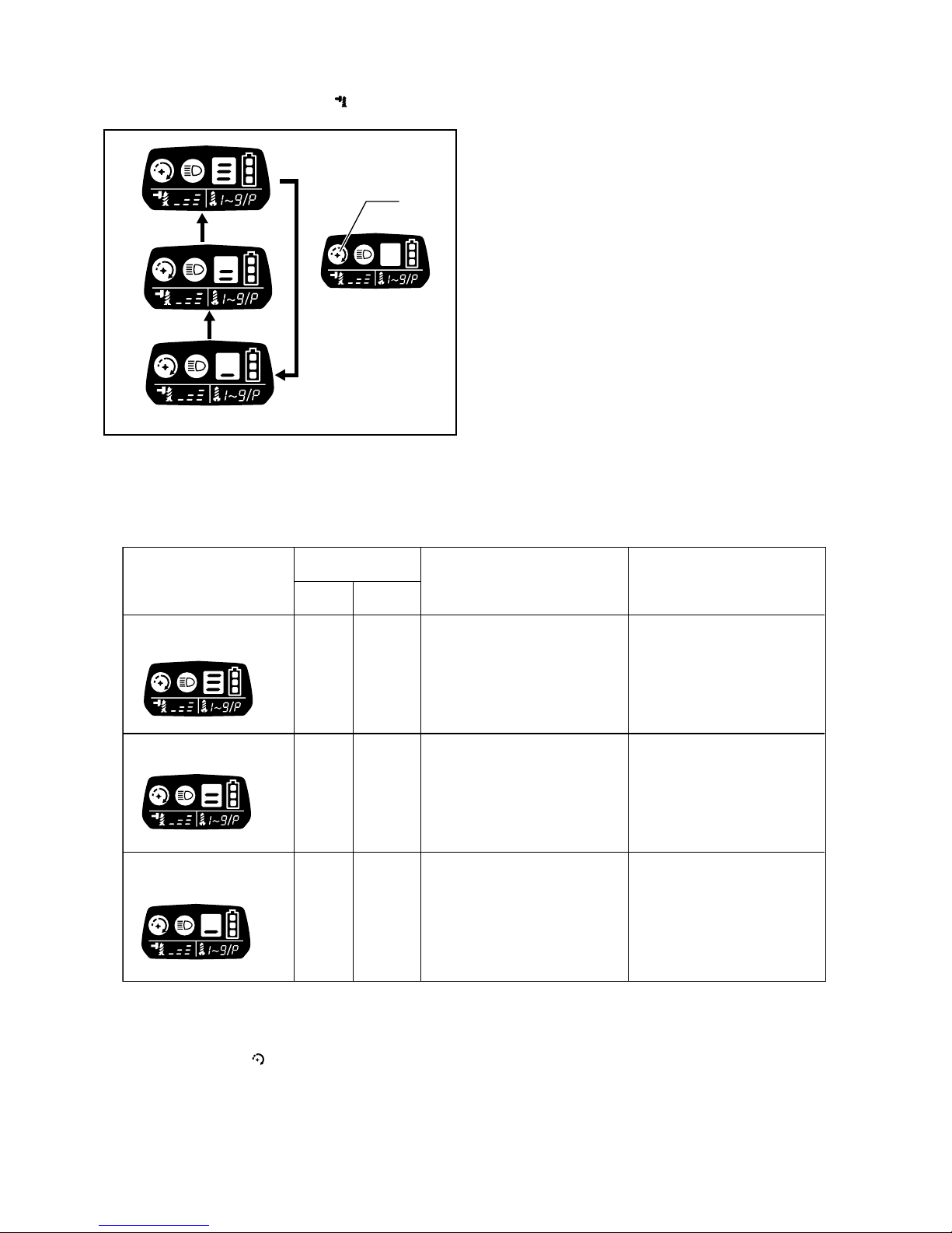
When driving wood screws or bolts, point the arrow at the
mark for impact driver mode. The impact force can be
adjusted on the LED display.
When drilling into concrete or tiles, point the arrow at the
mark for hammer drill mode.
When drilling into wood or metal, point the arrow at the
mark for drill mode.
When driving small wood screws or machine screws,
point the arrow at the mark for screwdriver mode. The
fastening torque can be adjusted on the LED display.
CAUTION:
• Always set the arrow correctly to either mode mark.
If you operate the tool with the action mode
changing ring positioned halfway between the
mode marks, the tool may be damaged.
• When turning the action mode changing ring, make
sure that the tool stops. If the ring does not easily
move, pull the switch trigger slightly to rotate the
spindle and then move the ring.
• In the hammer drill mode or drill mode, the blowing
force or torque is not adjustable. In those modes,
the number on the LED display will be off.

7
Changing the impact force
(impact driver mode " ")
1
2
3
4
5
012244
Impact force grade
displayed on panel
Maximum blows
Application Work
Hard
Medium
Soft
Tightening when force
and speed are desired.
Tightening when a good
finishing is needed.
Tightening when excessive
tightening need to be avoided
because of potentially clogged
female screw and broken or
damaged screw head.
Tightening in underwork
material/ Tightening long
screws/ Tightening bolts.
Tightening in the finishing
board, plaster board.
Tightening sash screw/
Tightening small screws
such as M6.
3,200
(min )
-1
BTP131 BTP141
3,200
(min )
-1
2,400
(min )
-1
2,400
(min )
-1
1,200
(min )
-1
1,200
(min )
-1
012243
The impact force can be changed in three steps: hard,
medium and soft.
This allows a tightening suitable to the work.
Every time the button is pressed, the impact force
grade changes in three steps.
For approximately one minute after releasing the switch
trigger, the impact force can be changed.
NOTE:
During the operation of switch trigger, the impact force
grade cannot be changed.
1. Changed in three steps
2. Hard
3. Medium
4. Soft
5. Control button

8
Changing the torque setting
(screwdriver mode " ")
The fastening torque can be adjusted by pressing the
button in screwdriver mode.
The numbers on the LED display shows torque setting.
The fastening torque is minimum at the number 1 and
maximum at the number 9. The indication "P" is a special
mode for fastening self drilling screws.
Every time the button is pressed, the torque setting
changes from 1 to 9 and P, and then returns to 1.
The torque setting changes fast by keeping pressing the
button.
P mode is suitable for fastening self drilling screws into
steel plates in the following conditions.
• With speed change lever at "2" side, fastening max.
4 mm screw into total max. 3.2 mm steel plates.
• With speed change lever at "1" side, fastening max.
5 mm screw.
Before an actual operation, drive a trial screw into your
material or a piece of duplicate material to determine
which torque level is required for a particular application.
First, try to fasten the screw at "1". Then increase the
number to continue fastening. Hold the tool firmly during
operation.
CAUTION:
Don't fasten the machine screw on P mode. It may twist
your wrist suddenly and result in personal injury.
NOTE:
• Make sure to check the number on LED display
before operation. If the number is not indicated,
contact your nearest Makita service center.
• When the remaining battery capacity gets low in the
screwdriver mode, the light flashes a few times
when fastening the screw completely. In this case,
recharge the battery. If you keep operating, you
may not obtain the desired torque.
• During pulling the switch trigger, the torque setting
cannot be changed.
• For approximately one minute after releasing the
switch trigger, the torque setting can be changed. if
you want to change the torque setting after that,
pull the switch trigger again.
• The number of torque setting does not mean
specific torque rate.
Empty signal for remaining
battery capacity
Fig.9
The remaining battery capacity will be signaled on the
LED display when pulling the switch trigger.
The remaining battery capacity is shown as the following
table.
LED indicator status Remaining battery capacity
About 50% or more
About 20% - 50%
About less than 20%
012273
NOTE:
• When the LED display goes off, the tool is turned off
to save the battery power. To check the remaining
battery capacity, slightly pull the switch trigger.
• The LED display goes off approximately one
minute after releasing the switch trigger.
• When the temperature of the tool gets high, the
light flashes once per second for one minute, and
then the LED display goes off. In this case, cool
down the tool before operation.
ASSEMBLY
CAUTION:
• Always be sure that the tool is switched off and the
battery cartridge is removed before carrying out
any work on the tool.
Installing or removing driver/drill/socket bit
Fig.10
Use only the driver/drill/socket bit shown in the figure. Do
not use any other driver/drill/socket bit.
For tool with shallow bit hole
A=12mm
B=9mm
Use only these type of bit. Follow the
procedure (1).
(Note) Bit-piece is not necessary.
006348
For tool with deep bit hole
To install these types of bits, follow
the procedure (1).
To install these types of bits, follow
the procedure (2).
(Note) Bit-piece is necessary for
installing the bit.
A=17mm
B=14mm
A=12mm
B=9mm
011405

9
1. To install the bit, pull the sleeve and insert the bit
into the sleeve as far as it will go. Then release the
sleeve to secure the bit.
Fig.11
2.
To install the bit, insert the bit-piece and bit into the
sleeve as far as it will go. The bit-piece should be
inserted into the sleeve with its pointed end facing
in. Then release the sleeve to secure the bit.
Fig.12
To remove the bit, pull the sleeve in the direction of the
arrow and pull the bit out firmly.
CAUTION:
• Do not touch the drill bit shortly after operating as it
gets hot. Replace the drill bit after cooling it down.
NOTE:
• If the bit is not inserted deep enough into the sleeve,
the sleeve will not return to its original position and
the bit will not be secured. In this case, try
re-inserting the bit according to the instructions
above.
• After inserting the bit, make sure that it is firmly
secured. If it comes out, do not use it.
Hook (Optional accessory)
Fig.13
CAUTION:
• When installing the hook, tighten the screw firmly.
Failure to do so may cause the breakage of the tool
or personal injury.
The hook is convenient for temporarily hanging the tool.
This can be installed on either side of the tool.
To install the hook, insert it into a groove in the tool
housing on either side and then secure it with a screw. To
remove, loosen the screw and then take it out.
OPERATION
Fig.14
CAUTION:
• Always insert the battery cartridge all the way until it
locks in place with a little click. If you can see the
red indicator on the upper side of the button, it is not
locked completely. Install it fully until the red
indicator cannot be seen. If not, it may accidentally
fall out of the tool, causing injury to you or someone
around you.
• If the tool is operated continuously until the battery
cartridge has discharged, allow the tool to rest for
15 minutes before proceeding with a fresh battery.
Impact driver mode " "
Screwdriving
Hold the tool firmly and place the point of the driver bit in
the screw head. Apply forward pressure to the tool to the
extent that the bit will not slip off the screw and turn the
tool on to start operation.
Tightening bolts
The proper fastening torque may differ depending upon
the kind or size of the screw/bolt, the material of the
workpiece to be fastened, etc. The relation between
fastening torque and fastening time is shown in the
figures.
120
100
80
60
40
20
Standard bolt
N m
Fastening torque
Fastening time
Proper fastening torque
(kgf cm)
(1224)
(1020)
(816)
(612)
(408)
(204)
(S)
0 1.0 2.0 3.0
(M14)
(M12)
(M10)
(M8)
0
M14
M12
M10
M8
012423

10
120
100
80
60
40
20
High tensile bolt
N m
Fastening torque
Fastening time
Proper fastening torque
(kgf cm)
(1224)
(1020)
(816)
(612)
(408)
(204)
(S)
0 1.0 2.0 3.0
(M12)
(M10)
(M8)
0
M12
M10
M8
012425
NOTE:
• When the action mode is set to impact driver mode,
make sure that the tool impacts properly by
fastening a wood screw before operation. If the tool
does not work properly, contact your nearest
Makira service center.
• Hold the tool pointed straight at the screw.
• Use the proper bit for the head of the screw/bolt
that you wish to use.
• When fastening screw M8 or smaller, carefully
adjust pressure on the switch trigger so that the
screw is not damaged.
• If you tighten the screw for a time longer than
shown in the figures, the screw or the point of the
driver bit may be overstressed, stripped, damaged,
etc. Before starting your job, always perform a test
operation to determine the proper fastening time for
your screw.
The fastening torque is affected by a wide variety of
factors including the following. After fastening, always
check the torque with a torque wrench.
1. When the battery cartridge is discharged almost
completely, voltage will drop and the fastening
torque will be reduced.
2. Driver bit or socket bit
Failure to use the correct size driver bit or socket
bit will cause a reduction in the fastening torque.
3. Bolt
• Even though the torque coefficient and the
class of bolt are the same, the proper fastening
torque will differ according to the diameter of
bolt.
• Even though the diameters of bolts are the
same, the proper fastening torque will differ
according to the torque coefficient, the class of
bolt and the bolt length.
4.
The manner of holding the tool or the material of
driving position to be fastened will affect the torque.
5. Operating the tool at low speed will cause a
reduction in the fastening torque.
Hammer drill mode " "
CAUTION:
• Always hold the tool firmly during operation. There
is a tremendous and sudden twisting force exerted
on the tool/bit at the time of hole break-through,
when the hole becomes clogged with chips and
particles, or when striking reinforcing rods
embedded in the concrete.
Be sure to use a tungsten-carbide tipped bit.
Position the bit at the desired location for the hole, then
pull the switch trigger. Do not force the tool. Light
pressure gives best results. Keep the tool in position and
prevent it from slipping away from the hole.
Do not apply more pressure when the hole becomes
clogged with chips or particles. Instead, run the tool at an
idle, then remove the bit partially from the hole. By
repeating this several times, the hole will be cleaned out
and normal drilling may be resumed.
Drilling mode " "
CAUTION:
•
Pressing excessively on the tool will not speed up
the drilling. In fact, this excessive pressure will only
serve to damage the tip of your bit, decrease the tool
performance and shorten the service life of the tool.
• There is a tremendous force exerted on the tool/bit
at the time of hole break through. Hold the tool
firmly and exert care when the bit begins to break
through the workpiece.
• A stuck bit can be removed simply by setting the
reversing switch to reverse rotation in order to back
out. However, the tool may back out abruptly if you
do not hold it firmly.
• Always secure small workpieces in a vise or similar
hold-down device.
• Do not pull the switch trigger repeatedly when the
motor is locked. It may damage the tool.
For drilling in wood, the best results are obtained with
wood drills equipped with a guide screw. The guide screw
makes drilling easier by pulling the bit into the workpiece.
For drilling in metal, to prevent the bit from slipping when
starting a hole, make an indentation with a center-punch
and hammer at the point to be drilled. Place the point of
the bit in the indentation and start drilling.
Use a cutting lubricant when drilling metals. The
exceptions are iron and brass which should be drilled dry.

11
Screwdriver mode " "
CAUTION:
• Adjust the number on the LED display to the proper
torque level for your work.
• Make sure that the driver bit is inserted straight in
the screw head, or the screw and/or bit may be
damaged.
• Hold the tool firmly. When the clutch cuts in or
refastening, a sudden twisting force may occur and
it can twist your wrist.
Place the point of the driver bit in the screw head and
apply pressure to the tool. Start the tool slowly and then
increase the speed gradually.
NOTE:
• This tool employs an electronic clutch. The tool
stops automatically when the clutch cuts in. To keep
operating, release the switch trigger once.
• When driving wood screws, predrill pilot holes to
make driving easier and to prevent splitting of the
workpiece. See the chart.
Nominal diameter of wood screw
(mm)
Recommended sizeof pilot hole
(mm)
3.12.0- 2.2
3.5 2.2- 2.5
3.82.5 - 2.8
4.5 2.9- 3.2
4.83.1- 3.4
5.13.3- 3.6
5.5 3.7- 3.9
5.84.0- 4.2
6.14.2- 4.4
006421
NOTE:
• See the following chart for the relation between the
number of torque setting and fastening torque rate.
The fastening torque rate will be different depends
on materials. Make a test fastening to get the
desired torque before operation.
Fastening torque rate
Number
on LED
Display
1
3
5
7
9
Low (1) High (2)
Approx. 2.5N m
(Approx. 25.5 kgf. cm)
Approx. 4.6N m
(Approx. 46.9kgf. cm)
Approx. 8.1N m
(Approx. 82.6kgf. cm)
Approx. 10.0N m
(Approx. 102.0kgf. cm)
Approx. 11.5N m
(Approx. 117.3kgf. cm)
Approx. 1.1N m
(Approx. 11.2kgf. cm)
Approx. 2.0N m
(Approx. 20.4 kgf. cm)
Approx. 3.0N m
(Approx. 30.6kgf. cm)
Approx. 4.0N m
(Approx. 40.8kgf. cm)
Approx. 5.8N m
(Approx. 59.1kgf. cm)
.
.
.
.
.
.
.
.
.
.
012276
MAINTENANCE
CAUTION:
• Always be sure that the tool is switched off and the
battery cartridge is removed before attempting to
perform inspection or maintenance except for the
following troubleshooting related to the light.
• Never use gasoline, benzine, thinner, alcohol or the
like. Discoloration, deformation or cracks may
result.
To maintain product SAFETY and RELIABILITY, repairs,
any other maintenance or adjustment should be
performed by Makita Authorized Service Centers, always
using Makita replacement parts.
OPTIONAL ACCESSORIES
CAUTION:
• These accessories or attachments are
recommended for use with your Makita tool
specified in this manual. The use of any other
accessories or attachments might present a risk of
injury to persons. Only use accessory or
attachment for its stated purpose.
If you need any assistance for more details regarding
these accessories, ask your local Makita Service Center.
• Screw bits
• Hook
• Plastic carrying case
• Various type of Makita genuine batteries and
chargers
NOTE:
• Some items in the list may be included in the tool
package as standard accessories. They may differ
from country to country.

12
SVENSKA (Originalbruksanvisning)
Förklaring till översiktsbilderna
1-1. Röd indikator
1-2. Knapp
1-3. Batterikassett
2-1. Stjärnmarkering
3-1. Avtryckare
4-1. Lampa
5-1. LED-skärm
5-2. Lampknapp
6-1. Reverseringsknapp
7-1. Hastighetsknapp
8-1. Lägesmarkering
8-2. Ring för byte av arbetsläge
8-3. Pil
9-1. Batterikapacitet
11-1. Bits
11-2. Hylsa
12-1. Bits
12-2. Adapter
12-3. Hylsa
13-1. Spår
13-2. Krok
13-3. Skruv
SPECIFIKATIONER
Modell BTP131 BTP141
Maskinskruv 4 mm - 8 mm
Standardbult 5 mm - 14 mm
Åtdragningskapacitet
Höghållfast bult 5 mm - 12 mm
Obelastat varvtal (min
-1
) (Mjuk/ Medel / hård)
0 - 1 400 / 0 - 2 200 / 0 - 2 800 0 - 1 300 / 0 - 2 200 / 0 - 2 700
Slagborrningsläge
Slag per minut (Mjuk/ Medel / hård) 0 - 1 200 / 0 - 2 400 / 0 - 3 200
Låg (1) / Hög (2)
Obelastat varvtal (min-1) 0 - 700 / 0 - 2 800 0 - 700 / 0 - 2 700
Slag per minut (min-1) 0 - 8 400 / 0 - 32 400
Borrhammarläge
Borrkapacitet/betong 8 mm
Stål 10 mm / 6,5 mm
Trä 21 mm / 12 mm
Borrningsläge Borrkapacitet
Obelastat varvtal (min
-1
)
0 - 700 / 0 - 2 800 0 - 700 / 0 - 2 700
Maskinskruv 3,5 mm - 6 mm / 4 mm - 6 mm
Självborrande skruv
4 mm, 5 mm / 4 mm (Max. 3,2 mm tjocklek.)
Skruvdragarläge
Åtdragningskapacitet
Obelastat varvtal
(min-1)
0 - 300 / 0 - 1 100 (beror på momentinställning)
0 - 600 / 0 - 2 300 (P-läge)
Nettovikt (med batterikassett) 1,5 kg ( med batteri BL1415)
1,7 kg ( med batteri BL1430)
1,6 kg ( med batteri BL1815)
1,8 kg ( med batteri BL1830)
Märkspänning 14,4 V likström 18 V likström
• På grund av vårt pågående program för forskning och utveckling kan dessa specifikationer ändras utan föregående meddelande.
• Specifikationer och batterikassett kan variera från land till land.
• Vikt med batterikassett i enlighet med EPTA-procedur 01/2003
ENE033-1
Användningsområde
Verktyget är avsett för skruvdragning i trä, metall och
plast.
ENG905-1
Buller
Typiska A-vägda bullernivån är mätt enligt EN60745:
Modell BTP131
Ljudtrycksnivå (LpA): 85 dB(A)
Ljudtrycksnivå (LWA): 96 dB(A)
Mättolerans (K) : 3 dB(A)
Modell BTP141
Ljudtrycksnivå (LpA): 85 dB(A)
Ljudtrycksnivå (LWA): 96 dB(A)
Mättolerans (K) : 3 dB(A)
Använd hörselskydd
ENG900-1
Vibration
Vibrationens totalvärde (tre-axlars vektorsumma) mätt
enligtEN60745:
Modell BTP131
Arbetsläge: slagborrning i cement
Vibrationsemission (ah,ID): 13 m/s2
Mättolerans (K): 1,5 m/s2
Arbetsläge: maskinens maximala moment för
slagåtdragning
Vibrationsemission (ah) : 8,5 m/s2
Mättolerans (K): 2 m/s2

13
Arbetsläge: borrning i metall
Vibrationsemission (ah,D) : 2,5 m/s2eller mindre
Mättolerans (K): 1,5 m/s2
Modell BTP141
Arbetsläge: slagborrning i cement
Vibrationsemission (ah,ID): 13 m/s2
Mättolerans (K): 1,5 m/s2
Arbetsläge: maskinens maximala moment för
slagåtdragning
Vibrationsemission (ah) : 10,5 m/s2
Mättolerans (K): 1,5 m/s2
Arbetsläge: borrning i metall
Vibrationsemission (ah,D) : 2,5 m/s2eller mindre
Mättolerans (K): 1,5 m/s2
ENG901-1
• Det deklarerade vibrationsemissionsvärdet har
uppmätts i enlighet med standardtestmetoden och
kan användas för jämförandet av en maskin med
en annan.
• Det deklarerade vibrationsemissionsvärdet kan
också användas i preliminär bedömning av
exponering för vibration.
VARNING!
• Viberationsemissionen under faktisk användning
av maskinen kan skilja sig från det deklarerade
emissionsvärdet, beroende på hur maskinen
används.
•
Se till att hitta säkerhetsåtgärder som kan skydda
användaren och som grundar sig på en
uppskattning av exponering i verkligheten (ta med i
beräkningen alla delar av användandet såsom antal
gånger maskinen är avstängd och när den körs på
tomgång samt då startomkopplaren används).
ENH101-15
Gäller endast Europa
EU-konformitetsdeklaration
Vi Makita Corporation som ansvariga tillverkare
deklarerar att följande Makita-maskin(er):
Maskinbeteckning:
Batteridriven slagskruvdragare med 4 lägen
Modellnr./ Typ: BTP131, BTP141
är för serieproduktion och
Följer följande EU-direktiv:
2006/42/EC
Och är tillverkade enligt följande standarder eller
standardiseringsdokument:
EN60745
Den tekniska dokumentationen förs av vår auktoriserade
representant i Europa som är:
Makita International Europe Ltd.
Michigan Drive, Tongwell,
Milton Keynes, Bucks MK15 8JD, England
14.4.2011
000230
Tomoyasu Kato
Direktör
Makita Corporation
3-11-8, Sumiyoshi-cho,
Anjo, Aichi, 446-8502, JAPAN
GEA010-1
Allmänna säkerhetsvarningar för
maskin
VARNING Läs igenom alla säkerhetsvarningar
och instruktioner. Underlåtenhet att följa varningar och
instruktioner kan leda till elektrisk stöt, brand och/eller
allvarliga personskador.
Spara alla varningar och instruktioner
för framtida referens.
GEB078-2
SÄKERHETSVARNINGAR FÖR
BATTERIDRIVEN 4-LÄGES
SLAGSKRUVDRAGARE
1. Bär hörselskydd vid slagborrning. Kraftigt
buller kan orsaka hörselskador.
2. Använd extrahandtag, om det levereras med
maskinen. Att tappa kontrollen över maskinen
kan leda till personskador.
3. Håll maskinen i de isolerade handtagen om det
finns risk för att skruvdragaren kan komma i
kontakt med en dold elkabel. Om skruvdragaren
kommer i kontakt med en strömförande ledning
blir maskinens metalldelar strömförande och kan
ge operatören en elektrisk stöt.
4. Håll maskinen i de isolerade handtagen om det
finns risk för att skärverktyget kan komma i
kontakt med en dold elkabel. Om skärverktyget
kommer i kontakt med en strömförande ledning
blir maskinens metalldelar strömförande och kan
ge operatören en elektrisk stöt.
5. Se till att du hela tiden har ett säkert fotfäste.
Se till att ingen står under dig när maskinen
används på hög höjd.
6. Håll maskinen stadigt.
7. Håll händerna på avstånd från roterande delar.
8. Lämna inte maskinen igång. Använd endast
maskinen när du håller den i händerna.
9. Rör inte vid borr eller arbetsstycke omedelbart
efter användning eftersom de kan vara extremt
varma och orsaka brännskador.
10. Vissa material kan innehålla giftiga kemikalier.
Se till att du inte andas in damm eller får det
på huden. Följ anvisningarna i leverantörens
materialsäkerhetsblad.

14
SPARA DESSA ANVISNINGAR.
VARNING!
GLÖM INTE att noggrant följa
säkerhetsanvisningarna för maskinen även efter det
att du har blivit van att använda den. OVARSAM
hantering eller underlåtenhet att följa
säkerhetsanvisningarna i denna bruksanvisning kan
leda till allvarliga personskador.
ENC007-7
VIKTIGA
SÄKERHETSANVISNINGAR
FÖR BATTERIKASSETT
1. Innan batterikassetten används ska alla
instruktioner och varningsmärken på (1)
batteriladdaren, (2) batteriet och (3) produkten
läsas.
2. Montera inte isär batterikassetten.
3. Om driftstiden blivit avsevärt kortare ska
användningen avbrytas omedelbart. Det kan
uppstå överhettning, brännskador och t o m
en explosion.
4. Om du får elektrolyt i ögonen ska de sköljas
med rent vatten och läkare uppsökas
omedelbart. Det finns risk för att synen
förloras.
5. Kortslut inte batterikassetten.
(1) Rör inte vid polerna med något
strömförande material.
(2) Undvik att förvara batterikassetten
tillsammans med andra metallobjekt som t
ex spikar, mynt etc.
(3) Skydda batteriet mot vatten och regn.
Ett kortslutet batteri kan orsaka ett stort
strömflöde, överhettning, risk för brännskador
och maskinen kan till och med gå sönder.
6. Förvara inte maskinen och batterikassetten på
platser där temperaturen kan nå eller
överstiga 50 ゚C (122 ゚F).
7. Bränn inte upp batterikassetten även om den
är svårt skadad eller helt utsliten.
Batterikassetten kan explodera i öppen eld.
8. Var försiktig så att du inte råkar tappa batteriet
och utsätt det inte för stötar.
9. Använd inte ett skadat batteri.
SPARA DESSA ANVISNINGAR.
Tips för att uppnå batteriets maximala
livslängd
1. Ladda batterikassetten innan den är helt
urladdad.
Sluta att använda maskinen och ladda
batterikassetten när du märker att kraften
avtar.
2. Ladda aldrig en fulladdad batterikassett.
Överladdning förkortar batteriets livslängd.
3. Ladda batterikassetten vid rumstemperaturer
mellan 10 ゚C och 40 ゚C (50 ゚F - 104 ゚F). Låt en
varm batterikassett svalna innan den laddas.
4. Ladda batterikassetten om du inte har använt
den på mer än sex månader.
FUNKTIONSBESKRIVNING
FÖRSIKTIGT!
• Se alltid till att maskinen är avstängd och
batterikassetten borttagen innan du justerar eller
kontrollerar maskinens funktioner.
Montera eller demontera batterikassetten
Fig.1
• Stäng alltid av maskinen innan du monterar eller tar
bort batterikassetten.
• Ta bort batterikassetten genom att skjuta ner
knappen på kassettens framsida samtidigt som du
drar ut batterikassetten.
• Montera batterikassetten genom att rikta in tungan
på batterikassetten mot spåret i höljet och skjut den
på plats. För alltid in batterikassetten hela vägen
tills den låser fast med ett klick. Om du kan se den
röda indikatorn på knappens ovansida är
batterikassetten inte låst ordentligt. Skjut in den helt
tills den röda indikatorn inte syns längre. I annat fall
kan den oväntat fall ur maskinen och skada dig
eller någon annan.
Ta inte i för hårt när du monterar batterikassetten. Om
kassetten inte lätt glider på plats är den felinsatt.
Batteriskyddssystem (litium-ion-batteri med
stjärnmarkering)
Fig.2
Litium-ion-batterier med en stjärnmarkering är utrustade
med ett skyddssystem. Detta system bryter automatiskt
strömmen till maskinen för att förlänga batteriets
livslängd.
Maskinen stanna automatiskt under användningen om
maskinen och/eller batteriet hamnar i en av följande
situationer:
• Överbelastad:
Maskinen används på ett sätt som orsakar att
den förbrukar onormalt mycket ström.
I detta läge ska du släppa avtryckaren på
maskinen och stoppa handlingen som
orsakar maskinen att bli överbelastad. Tryck
sedan in avtryckaren igen för att starta om.
Om maskinen inte startar är batteriet
överhettat. I detta läge ska du låta batteriet
svalna innan du trycker in avtryckaren igen.
• Batterispänningen faller:
Den kvarvarande batterikapaciteten är för låg
och maskinen fungerar inte. I detta läge tar du
bort batteriet och laddar det.

15
Avtryckarens funktion
Fig.3
FÖRSIKTIGT!
• Innan du monterar batterikassetten i maskinen ska
du alltid kontrollera att avtryckaren fungerar och
återgår till läget "OFF" när du släpper den.
Tryck in avtryckaren för att starta maskinen. Hastigheten
ökar genom att du trycker hårdare på avtryckaren. Släpp
avtryckaren för att stanna maskinen.
OBS!
• Maskinen stannar tre minuter efter det att du tryckt
in avtryckaren.
Tända frontlampan
FÖRSIKTIGT!
• Titta inte direkt i lampan eller direkt i ljuskällan.
Fig.4
Fig.5
Varje gång som lampknappen på LED-skärmen
trycks in, ändras lampstatusen omväxlande från ON till
OFF och från OFF till ON.
När lampknappen är i läget ON, trycker du in avtryckaren
för att tända lampan. För att släcka, släpper du den och
lampan slocknar efter cirka 10 sekunder.
Med lampknappen i läget OFF tänds inte lampan, även
om avtryckaren trycks in.
OBS!
•
Tryck in avtryckaren för att kontrollera lampstatusen.
När lampan tänds genom att avtryckaren trycks in,
är lampströmbrytaren i läget ON. När lampan inte
tänds, är lampströmbrytare i läget OFF.
• När avtryckaren är intryckt kan lampstatusen inte
ändras.
• Efter cirka 10 sekunder när avtryckaren släppts,
kan lampstatusen ändras.
Reverseringsknappens funktion
Fig.6
Denna maskin har en reverseringsknapp för att byta
rotationsriktning. Tryck in reverseringsknappen från
sidan A för medurs rotation och från sidan B för moturs
rotation.
När reverseringsknappen är i neutralt läge fungerar inte
avtryckaren.
FÖRSIKTIGT!
• Kontrollera alltid rotationsriktningen före
användning.
• Använd endast reverseringsknappen när maskinen
stannat helt. Maskinen kan skadas om du byter
rotationsriktning medan den fortfarande roterar.
• Placera alltid reverseringsknappen i neutralt läge
när du inte använder maskinen.
Hastighetsändring
Fig.7
OBSERVERA:
• Var noga när du ändrar läge på hastighetsknappen.
Om du använder maskinen och hastighetsknappen
står halvvägs mellan sida "1" och sida "2" kan
maskinen skadas.
• Ändra inte hastighetsknappen medan maskinen
roterar. Maskinen kan skadas.
• Tvinga inte knappen till sida “1” i
slagskruvdragarläge. Maskinen kan skadas.
För att byta hastighet stänger du först av maskinen. Skjut
sedan hastighetsknappen till "2" för hög hastighet eller till
"1" för låg hastighet. Kontrollera att hastighetsknappen
står i rätt läge innan du börjar arbeta. Använd rätt
hastighet för jobbet.
När du vrider inställningsringen för byte av arbetsläge till
slagskruvdragarläge, ska du skjuta hastighetsknappen
till sidan “2”.
Välja arbetsläge
Fig.8
Denna maskin använder sig av en inställningsring för
byte av arbetsläge. Välja en av de 4 lägen som bäst
passar det arbete du ska utföra genom att vrida denna
ring.
När du skruvar träskruvar eller bultar ska du ställa in
pilen på markeringen för slagskruvdragarläge.
Slagstyrkan kan justeras på LED-skärmen.
Vid borrning i betong eller kakel ska pilen peka på
markeringen för borrhammarläge.
Vid borrning i trä eller metall ska pilen peka på
markeringen för borrläge.
Vid skruvning av små träskruvar eller maskinskruvar ska
pilen peka på markeringen för skruvdragarläge.
Åtdragningsmomentet kan justeras på LED-skärmen.
FÖRSIKTIGT!
• Ställ alltid in pilen korrekt på någon av
lägesmarkeringarna. Om du använder maskinen
med inställningsringen för byte av arbetsläge
placerad halvvägs mellan lägesmarkeringarna kan
maskinen skadas.
• Kontrollera att maskinen har stannat innan du
vrider inställningsringen för byte av arbetsläge. Om
ringen inte går att vrida lätt ska du trycka in
avtryckaren lätt för att vrida spindeln och sedan
vrida ringen.
• I borrhammarläget eller borrläget är inte
slagstyrkan eller momentet justerbart. Siffran på
LED-skärmen visas inte i dessa lägen.

16
Ändring av slagstyrka
(slagskruvdragarläge ” ”)
1
2
3
4
5
012244
Nivån för slagstyrkan
visas på panelen
Maximalt antal slag
Användning Arbete
Hård
Medel
Mjuk
Åtdragning när styrka och
hastighet önskas.
Åtdragning när ett finare
avslut behövs.
Åtdragning när kraftig
åtdragning bör undvikas på
grund av potentiellt blockerad
skruv och avbrutet eller skadat
skruvhuvud.
Åtdragning i
underlagsmaterial/ Åtdragning
av långa skruvar/ Åtdragning
av bultar.
Åtdragning i träyta, gipsyta.
Åtdragning av
fönsterskruv/ Åtdragning av
små skruvar såsom M6.
3 200
(min )
-1
BTP131 BTP141
3 200
(min )
-1
2 400
(min )
-1
2 400
(min )
-1
1 200
(min )
-1
1 200
(min )
-1
012243
Slagstyrkan kan ändras i tre steg: hård, mellan och mjuk.
Detta tillåter en passande åtdragning för arbetet.
Varje gång knappen trycks in, ändras nivån för
slagstyrkan i tre steg.
Ungefär en minut efter det att avtryckaren har släppts,
kan slagstyrkan ändras.
OBS!
När avtryckaren är aktiverad kan inte nivån för
slagstyrkan ändras.
1. Ändras i tre steg
2. Hård
3. Medel
4. Mjuk
5. Kontrollknapp

17
Ändring av momentinställningen
(skruvdragarläge “ ”)
Åtdragningsmomentet kan justeras genom att trycka på
knappen i skruvdragarläge.
Siffrorna på LED-skärmen visar momentinställning.
Åtdragningsmomentet är lägst för siffran 1 och högst för
siffran 9. Indikationen ”P” är ett specialläge för
åtdragning av självborrande skruvar.
Varje gång som knappen trycks in, ändras
momentinställningen från 1 till 9 och P, och återgår sedan
till 1.
Momentinställningen ändras snabbt genom att fortsätta
hålla in knappen.
P-läget är passande för åtdragning av självborrande
skruvar i stålplåt under följande förhållanden.
• Med hastighetsknappen mot sida “2”, åtdragning av
max. 4 mm skruv i totalt max. 3,2 mm stålplåt.
• Med hastighetsknappen mot sida “1”, åtdragning av
max. 5 mm skruv.
Innan du börjar arbeta ska du skruva i en provskruv i ditt
material eller i ett stycke av samma material, så att du vet
vilken momentnivå som passar för en viss applikation.
Försök först att dra åt skruven med “1”. Öka sedan siffran
för att fortsätta åtdragningen. Håll maskinen stadigt
under användningen.
FÖRSIKTIGT!
Dra inte åt maskinskruven i P-läget. Det kan plötsligt
vrida din handled och orsaka personskada.
OBS!
• Kontrollera siffran på LED-skärmen före
användning. Om siffran inte visas ska du kontakta
ditt närmaste servicecenter för Makita.
• När den kvarvarande batterikapaciteten blir låg i
skruvdragarläget, blinkar ljuset några gånger när
skruven dras åt helt. Ladda batteriet nu. Om du
fortsätter att arbeta kanske du inte får önskat
moment.
• När du har avtryckaren intryckt går det inte att
ändra momentinställningen.
• Ungefär en minut efter det att du har släppt
avtryckaren kan momentinställningen ändras. Om
du vill ändra momentinställningen efter det ska du
trycka in avtryckaren igen.
• Antalet momentinställningar betyder inte specifikt
momentvärde.
Varningssignal för återstående
batterikapacitet
Fig.9
Kvarvarande batterikapacitet signaleras på
LED-skärmen när avtryckaren trycks in.
Den kvarvarande batterikapaciteten visas i följande
tabell.
Status för diodindikator (LED)
Återstående batterikapacitet
Ungefär 50% eller mer
Ungefär 20% - 50%
Ungefär mindre än 20%
012273
OBS!
• När LED-skärmen släcks stängs maskinen av för
att spara batteriet. Tryck in avtryckaren lätt för att
kontrollera kvarvarande batterikapacitet.
• LED-skärmen släcks ungefär en minut efter det att
avtryckaren har släppts.
• När maskintemperaturen blir hög blinkar ljuset en
gång per sekund i en minut och sedan stängs
LED-skärmen av. Om så är fallet, låt maskinen
svalna innan du använder den igen.
MONTERING
FÖRSIKTIGT!
• Se alltid till att maskinen är avstängd och
batterikassetten borttagen innan du underhåller
maskinen.
Montering eller borttagning av
skruvbit/borrbit/hylsbit
Fig.10
Använd endast det skruvbit/borrbit/hylsbit som visas i
figuren. Använd inga andra bits.
För maskin med grunt bitshål
A=12mm
B=9mm
Använd endast dessa typer av borr/verktyg.
Följ monteringsanvisningen (1).
(Observera) Adaptern behövs inte.
006348
För maskin med djupt bitshål
Följ monteringsanvisningen (1)
för dessa typer av borr/verktyg.
Följ monteringsanvisningen (2)
för dessa typer av borr/verktyg.
(Observera) Adaptern behövs inte
för att montera borret/verktyget.
A=17mm
B=14mm
A=12mm
B=9mm
011405

18
1. För att montera bitset drar du i hylsan och sätta i
bitset i hylsan så långt det går. Släpp sedan hylsan
för att fästa bitset.
Fig.11
2. För att montera bitset ska du sätta i bits-biten och
sedan bitset i hylsan så långt det går. Bits-biten
ska föras in i hylsan med sin spetsiga ände vänd
inåt. Släpp sedan hylsan för att fästa bitset.
Fig.12
Ta ut bitset genom att dra hylsan i pilens riktning och dra
ut bitset.
FÖRSIKTIGT!
• Rör inte borrbitset kort efter användning eftersom
det blir varmt. Byt ut borrbitset efter att det har
svalnat.
OBS!
• Om bitset inte är isatt djupt nog i hylsan kommer
inte hylsan att gå tillbaka till sitt ursprungliga läge
och bitset fästs inte. Försök då att sätta i bitset på
nytt enligt instruktionerna ovan.
• Efter att bitset är isatt, kontrollera att det är
ordentligt fastskruvat. Om det åker ut ska du inte
använda det.
Krok (tillbehör)
Fig.13
FÖRSIKTIGT!
• När kroken monteras skall skruven dras åt
ordentligt. I annat fall kan det leda till att maskinen
förstörs eller att någon person skadas.
Kroken kan användas när du vill hänga upp verktyget
temporärt. Den kan monteras på endera sidan av
maskinen.
För att montera kroken sätter du i den i ett spår i
maskinhuset på endera sida och drar fast den med en
skruv. Ta bort kroken genom att skruva loss skruven.
ANVÄNDNING
Fig.14
FÖRSIKTIGT!
• Sätt alltid i batterikassetten ordentligt tills den låser
fast med ett klick. Om du kan se den röda
indikatorn på knappens ovansida är
batterikassetten inte låst ordentligt. Skjut in den helt
tills den röda indikatorn inte längre syns. I annat fall
kan den oväntat falla ur maskinen och skada dig
eller någon annan.
• Om maskinen används löpande tills batteriet är
tomt bör maskinen vila 15 minuter innan arbetet
fortsätter med ett laddat batteri.
Slagskruvdragarläge “ ”
Skruvåtdragning
Håll maskinen stadigt och placera spetsen på skruvbitset
i skruvhuvudet. Tryck maskinen framåt så att bitset inte
halkar av skruven och starta maskinen.
Dra åt bultar
Det korrekta åtdragningsmomentet för det som ska
fästas kan variera beroende på skruvens/bultens typ
eller storlek, arbetsstyckets material etc. Sambandet
mellan åtdragningsmomentet och åtdragningstiden visas
i figuren.
120
100
80
60
40
20
Standardbult
N m
Åtdragningsmoment
Åtdragningstid
Korrekt åtdragningsmoment
(kgf cm)
(1224)
(1020)
(816)
(612)
(408)
(204)
(S)
0 1,0 2,0 3,0
(M14)
(M12)
(M10)
(M8)
0
M14
M12
M10
M8
012423

19
120
100
80
60
40
20
Höghållfast bult
N m
Åtdragningsmoment
Åtdragningstid
Korrekt åtdragningsmoment
(kgf cm)
(1224)
(1020)
(816)
(612)
(408)
(204)
(S)
0 1,0 2,0 3,0
(M12)
(M10)
(M8)
0
M12
M10
M8
012425
OBS!
• När inställningsringen för byte av arbetsläge är
inställt på slagskruvdragarläge, ska du kontrollera
maskinens slagmekanism genom att prova att fästa
en träskruv före arbetet. Om maskinen inte arbetar
korrekt ska du kontakta ditt närmaste servicecenter
för Makita.
• Håll maskinen så att den pekar rakt på skruven.
• Använd korrekt bits för det skruv-/bulthuvud som du
vill använda.
• Justera försiktigt trycket på avtryckaren så att
skruven inte skadas när du fäster M8 skruv eller en
mindre storlek.
• Om du drar åt skruvarna under längre tid än vad
som visas i figuren kan skruven eller spetsen på
skruvbitset överbelastas, skadas, gängning bli
förstörd etc. Innan du påbörjar ett arbeta skall du
alltid göra en test för att bestämma den korrekta
åtdragningstiden för din skruv.
Åtdragningsmomentet påverkas av en mängd olika
faktorer, bland andra följande. Kontrollera alltid
åtdragningen med en momentnyckel efter
fastsättningen.
1. När batterikassetten nästan är helt urladdad
kommer spänningen att falla och
åtdragningsmomentet att minska.
2. Skruvbits eller hylsbits
Åtdragningsmomentet försämras om inte rätt
storlek används på skruvbits eller hylsbits.
3. Bult
• Även om momentkoefficienten och bultklassen
är densamma, beror det korrekta
åtdragningsmomentet på bultens diameter.
• Även om bultarnas diameter är samma
kommer det korrekta åtdragningsmomentet att
skilja sig åt i enlighet med
momentkoefficienten, bultklassen och bultens
längd.
4. Momentet påverkas även av fästmaterialet eller
hur maskinen hålls.
5. Att använda maskinen med låg hastighet minskar
åtdragningsmomentet.
Borrhammarläge ” ”
FÖRSIKTIGT!
• Håll alltid maskinen stadigt under användningen.
Maskinen/bitset utsätts för en plötslig och oerhört
stor vridande kraft vid hålgenomslaget, när hålet
fylls av spån och partiklar eller när du slår ner
förstärkningar i cement.
Använd ett hårdmetallbits.
Placera bitset där hålet ska vara och tryck sedan på
avtryckaren. Forcera inte maskinen. Ett lätt tryck ger bäst
resultat. Håll maskinen på rätt plats och hindra den från
att flyttas ur hålet.
Tryck inte hårdare när hålet fylls med spånor eller andra
partiklar. Kör istället maskinen på tomgång och ta ur
bitset ur hålet bit för bit. Genom att upprepa detta flera
gånger rensas hålet och normal borrning kan återupptas.
Borrläge ” ”
FÖRSIKTIGT!
• Borrningen går inte fortare för att du trycker hårdare
på maskinen. Detta extra tryck skadar bara toppen
på ditt borr, sänker maskinens prestanda och
förkortar maskinens livslängd.
• Det utvecklas en enorm kraft på maskinen/borret
vid hålgenomslaget. Håll ett stadigt tag i maskinen
och var försiktig när borret börjar tränga igenom
arbetsstycket.
• Ett borr som fastnat kan enkelt backas ur genom att
reversera borrningens rotationsriktning. Maskinen
kan dock backa för häftigt om du inte håller
ordentligt i den.
• Fäst alltid små arbetsstycken i ett städ eller
liknande infästningsenhet.
• Tryck inte in avtryckaren upprepade gånger när
motorn är låst. Det kan skada maskinen.
Vid borrning i trä uppnås det bästa resultatet med träborr
som är utrustade med en styrskruv. Styrskruven gör det
enklare att borra genom att den drar borret in i
arbetsstycket.
Vid borrning i metall kan du göra ett märke med en syl
och en hammare i punkten där hålet ska borras för att
borret inte ska halka när du börjar borra. Placera borrets
spets i sylhålet och påbörja borrningen.

20
Använd ett smörjmedel vid borrning i metall. Undantagen
är järn och mässing som ska borras torrt.
Borrmaskinsläge ” ”
FÖRSIKTIGT!
• Justera siffran på LED-skärmen till passande
momentnivå för ditt arbete.
• Se till att skruvbitset placeras rakt i skruvskallen
annars kan skruven och/eller bitset skadas.
• Håll stadigt i maskinen. När kopplingen slirar eller
fäster på nytt kan en plötslig vridande kraft uppstå
och den kan vrida din handled.
Placera spetsen på skruvbitset i skruvhuvudet och tryck
med maskinen. Starta maskinen sakta och öka sedan
hastigheten gradvis.
OBS!
• Denna maskin använder sig av en elektronisk
koppling. Maskinen stannar automatiskt när
kopplingen slirar. För att fortsätta arbeta släpper du
avtryckaren en gång.
• Vid skruvning i trä är det lämpligt att borra små
styrhål. Skruvdragningen blir enklare och träet
spricker inte så lätt. Se tabellen.
Nominell diameter på träskruven
(mm)
Rekommenderad storlek på styrhålet
(mm)
3,1 2,0 - 2,2
3,5 2,2 - 2,5
3,8 2,5 - 2,8
4,5 2,9 - 3,2
4,8 3,1 - 3,4
5,1 3,3 - 3,6
5,5 3,7 - 3,9
5,8 4,0 - 4,2
6,1 4,2 - 4,4
006421
OBS!
• Se följande tabell för relationen mellan siffran för
momentinställning och åtdragningsmomentvärdet.
Åtdragningsmomentvärdet är olika beroende på
material. Utför en teståtdragning för att få önskat
moment före arbetet.
Åtdragningsmomentvärde
Siffra på
LED-skärmen
1
3
5
7
9
Låg (1) Hög (2)
Ungefär 2,5 N m
(Ungefär 25,5 Kgf-cm)
Ungefär 4,6 N m
(Ungefär 46,9 Kgf-cm)
Ungefär 8,1 N m
(Ungefär 82,6 Kgf-cm)
Ungefär 10,0 N m
(Ungefär 102,0 Kgf-cm)
Ungefär 11,5 N m
(Ungefär 117,3 Kgf-cm)
Ungefär 1,1 N m
(Ungefär 11,2 Kgf-cm)
Ungefär 2,0 N m
(Ungefär 20,4 Kgf-cm)
Ungefär 3,0 N m
(Ungefär 30,6 Kgf-cm)
Ungefär 4,0 N m
(Ungefär 40,8 Kgf-cm)
Ungefär 5,8 N m
(Ungefär 59,1 kgf-cm)
.
.
.
.
.
.
.
.
.
.
012276
UNDERHÅLL
FÖRSIKTIGT!
• Se alltid till att maskinen är avstängd och att
batterikassetten är borttagen innan inspektion eller
underhåll utförs, förutom felsökning relaterad till
ljuset.
• Använd inte bensin, thinner, alkohol eller liknande.
Missfärgning, deformation eller sprickor kan uppstå
För att upprätthålla produktens SÄKERHET och
TILLFÖRLITLIGHET bör allt underhålls- och
justeringsarbete utföras av ett auktoriserat Makita
servicecenter och med reservdelar från Makita.
VALFRIA TILLBEHÖR
FÖRSIKTIGT!
• Dessa tillbehör och tillsatser rekommenderas för
användning tillsammans med den Makita-maskin
som denna bruksanvisning avser. Om andra
tillbehör eller tillsatser används kan det uppstå risk
för personskador. Använd endast tillbehören eller
tillsatserna för de syften de är avsedda för.
Kontakta ditt lokala Makita servicecenter om du behöver
ytterligare information om dessa tillbehör.
• Skruvbits
• Krok
• Förvaringsväska av plast
• Olika typer av originalbatterier och -laddare från
Makita
OBS!
• Några av tillbehören i listan kan vara inkluderade i
maskinpaketet som standardtillbehör. De kan
variera mellan olika länder.
Other manuals for BTP131
6
This manual suits for next models
1
Table of contents
Languages:
Other Makita Impact Driver manuals

Makita
Makita tw1000 User manual

Makita
Makita TD111D User manual

Makita
Makita 6953 User manual

Makita
Makita TD022D User manual

Makita
Makita 6940D User manual

Makita
Makita TD001G User manual

Makita
Makita XLT01 User manual

Makita
Makita DTD152 User manual

Makita
Makita DTS130 User manual

Makita
Makita 6905H User manual
Popular Impact Driver manuals by other brands

Truper
Truper IMP-1/2N manual

AIRTEC International
AIRTEC International New Master35 Maintenance manual

Cornwell Tools
Cornwell Tools bluePOWER CAT2238A operating manual

Villager
Villager VLN 3420 Original instruction manual

topmaster
topmaster TMP AIW 16 user manual

Sumake
Sumake ST-C504 Original instructions