Makita DUR365U User manual

DUR365U
EN Cordless Grass Trimmer INSTRUCTION MANUAL 7
UK Акумуляторна
газонокосарка
ІНСТРУКЦІЯ З
ЕКСПЛУАТАЦІЇ 20
PL Akumulatorowa wykaszarka
do trawy INSTRUKCJA OBSŁUGI 35
RO Motocositoare pentru iarbă
fără cablu MANUAL DE INSTRUCŢIUNI 48
DE Akku-Rasentrimmer BEDIENUNGSANLEITUNG 61
HU Vezeték nélküli fűkasza HASZNÁLATI KÉZIKÖNYV 75
SK Akumulátorová kosačka NÁVOD NA OBSLUHU 88
CS Akumulátorový vyžínač NÁVOD K OBSLUZE 101

1
2
3
1
2
2
1
1
1
2
Fig.1
Fig.2
Fig.3
Fig.4
Fig.5
Fig.6
Fig.7
Fig.8
2

1
2
1
1
1
2
3
2
1
Fig.14
1
2
Fig.16
Fig.9
Fig.10
Fig.11
Fig.12
Fig.13
Fig.15
3

2
3
1
3
4
5
2
6
1
1
2
3
1
2
3
45
1
42
3
5
1
Fig.17
Fig.18
Fig.19
Fig.20
Fig.21
Fig.22
Fig.23
Fig.24
4

1
2
1
1
1
2
1
80 mm (3-1/8”)
100 mm (3-15/16”)
2
1
3
Fig.25
Fig.26
Fig.27
Fig.28
Fig.29
Fig.30
Fig.31
Fig.32
5

1
1
2
Fig.39
Fig.33
Fig.34
Fig.35
Fig.36
Fig.37
Fig.38
6

7ENGLISH
ENGLISH (Original instructions)
SPECIFICATIONS
Model DUR365U
Type of handle Bike handle
No load speed 3,500 / 5,300 / 6,500 min-1
Overall length (without cutting tool) 1,754 mm
Nylon cord diameter 2.0 – 2.4 mm
Applicable cutting tool (country specic) Metal blade
(P/N 195150-5)
Nylon cutting head
(P/N 197296-3/ 198892-0/
198893-8)
Plastic blade
(P/N 198383-1)
Cutting diameter 230 mm 350 mm 255 mm
Rated voltage D.C. 36 V
Standard battery cartridge BL1815N / BL1820 / BL1820B BL1830 / BL1830B / BL1840 / BL1840B /
BL1850 / BL1850B / BL1860B
Net weight (with metal blade) 4.7 kg 5.2 kg
• Due to our continuing program of research and development, the specications herein are subject to change with-
out notice.
• Specications and battery cartridge may differ from country to country.
• Weight, with battery cartridge, according to EPTA-Procedure 01/2003
Noise Sound pressure
level average
Sound power level average Applicable standard
LPA (dB (A)) LWA (dB (A))
Uncertainty K (dB (A))
Metal blade 75 86 0.4 2000/14/EC
Plastic blade 73 84.4 1.0
Nylon cutting head 77 90 2.2
• Even if the sound pressure level listed above is 80 dB(A) or less, the level under working may exceed 80 dB(A).
Wear ear protection.
Vibration Left hand Right hand Applicable
standard
ah(m/s2)Uncertainty K
(m/s2)
ah(m/s2)Uncertainty K
(m/s2)
Metal blade ≤ 2.5 1.5 ≤ 2.5 1.5 EN786
Plastic blade ≤ 2.5 1.5 ≤ 2.5 1.5
Nylon cutting head ≤ 2.5 1.5 ≤ 2.5 1.5
NOTE: The declared vibration emission value has
been measured in accordance with the standard test
method and may be used for comparing one tool with
another.
NOTE: The declared vibration emission value
may also be used in a preliminary assessment of
exposure.
WARNING: The vibration emission during actual
use of the power tool can differ from the declared
emission value depending on the ways in which the
tool is used.
WARNING: Be sure to identify safety measures
to protect the operator that are based on an estima-
tion of exposure in the actual conditions of use (taking
account of all parts of the operating cycle such as
the times when the tool is switched off and when it is
running idle in addition to the trigger time).
Symbols
The following show the symbols used for the equip-
ment. Be sure that you understand their meaning before
use.
Take particular care and attention.
Read instruction manual.
Danger; be aware of thrown objects.
The distance between the tool and
bystanders must be at least 15 m.
Keep bystanders away.
15m(50FT)Keep distance at least 15 m.

8ENGLISH
Avoid kickback.
Wear a helmet, goggles and ear protection.
Wear protective gloves.
Wear sturdy boots with nonslip soles.
Steeltoed safety boots are recommended.
Do not expose to moisture.
Top permissible tool speed.
Ni-MH
Li-ion
Only for EU countries
Do not dispose of electric equipment or
battery pack together with household waste
material!
In observance of the European Directives,
on Waste Electric and Electronic
Equipment and Batteries and Accumulators
and Waste Batteries and Accumulators
and their implementation in accordance
with national laws, electric equipment and
batteries and battery pack(s) that have
reached the end of their life must be col-
lected separately and returned to an envi-
ronmentally compatible recycling facility.
EC Declaration of Conformity
For European countries only
The EC declaration of conformity is included as Annex A
to this instruction manual.
IMPORTANT SAFETY
INSTRUCTIONS
WARNING! Read all safety warnings and all
instructions. Failure to follow the warnings and instruc-
tions may result in electric shock, re and/or serious
injury.
Save all warnings and instruc-
tions for future reference.
Intended use
1. The cordless grass trimmer / brushcutter / string
trimmer is only intended for cutting grass, weeds,
bushes and undergrowth. It should not be used
for any other purpose such as edging or hedge
cutting as this may cause injury.
General instructions
1. Never allow people unfamiliar with these instruc-
tions, people (including children) with reduced
physical, sensory or mental capabilities, or lack
of experience and knowledge to use the tool.
Children should be supervised to ensure that they
do not play with the tool.
2. Before starting the tool, read this instruction man-
ual to become familiar with the handling of the
tool.
3. Do not lend the tool to a person with insufcient
experience or knowledge regarding handling of
brushcutters and string trimmers.
4. When lending the tool, always attach this instruc-
tion manual.
5. Handle the tool with the utmost care and attention.
6. Never use the tool after consuming alcohol or
drugs, or if feeling tired or ill.
7. Never attempt to modify the tool.
8. Follow the regulations about handling of brushcut-
ters and string trimmers in your country.
Personal protective equipment
► Fig.1
1. Wear safety helmet, protective goggles and pro-
tective gloves to protect yourself from ying debris
or falling objects.
2. Wear ear protection such as ear muffs to prevent
hearing loss.
3. Wear proper clothing and shoes for safe opera-
tion, such as a work overall and sturdy, non-slip
shoes. Do not wear loose clothing or jewelry.
Loose clothes, jewelry or long hair can be caught
in moving parts.
4. When touching the cutting blade, wear protec-
tive gloves. Cutting blades can cut bare hands
severely.
Work area safety
1. Operate the tool under good visibility and daylight
conditions only. Do not operate the tool in dark-
ness or fog.
2. Do not operate the tool in explosive atmospheres,
such as in the presence of ammable liquids,
gases or dust. The tool creates sparks which may
ignite the dust or fumes.
3. During operation, never stand on an unstable
or slippery surface or a steep slope. During the
cold season, beware of ice and snow and always
ensure secure footing.
4. During operation, keep bystanders or animals at
least 15 m away from the tool. Stop the tool as
soon as someone approaches.
5. Never operate the machine while people, espe-
cially children, or pets are nearby.
6. Before operation, examine the work area for
stones or other solid objects. They can be thrown
or cause dangerous kickback and result in serious
injury and/or property damage.
7. WARNING: Use of this product can create dust
containing chemicals which may cause respiratory
or other illnesses. Some examples of these chem-
icals are compounds found in pesticides, insec-
ticides, fertilizers and herbicides. Your risk from
these exposures varies, depending on how often
you do this type of work. To reduce your exposure
to these chemicals: work in a well ventilated area,
and work with approved safety equipment, such
as those dust masks that are specially designed to
lter out microscopic particles.

9ENGLISH
Electrical and battery safety
1. Do not expose the tool to rain or wet conditions.
Water entering the tool will increase the risk of
electric shock.
2. Do not use the tool if the switch does not turn it on
and off. Any tool that cannot be controlled with the
switch is dangerous and must be repaired.
3. Prevent unintentional starting. Ensure the switch
is in the off-position before installing a battery
pack, picking up or carrying the tool. Carrying the
tool with your nger on the switch or energising
the tool that have the switch on invites accidents.
4. Recharge only with the charger specied by the
manufacturer. A charger that is suitable for one
type of battery pack may create a risk of re when
used with another battery pack.
5. Use the tool only with specically designated
battery packs. Use of any other battery packs may
create a risk of injury and re.
6. When battery pack is not in use, keep it away from
other metal objects, like paper clips, coins, keys,
nails, screws or other small metal objects, that can
make a connection from one terminal to another.
Shorting the battery terminals together may cause
burns or a re.
7. Under abusive conditions, liquid may be ejected
from the battery; avoid contact. If contact acci-
dentally occurs, ush with water. If liquid contacts
eyes, seek medical help. Liquid ejected from the
battery may cause irritation or burns.
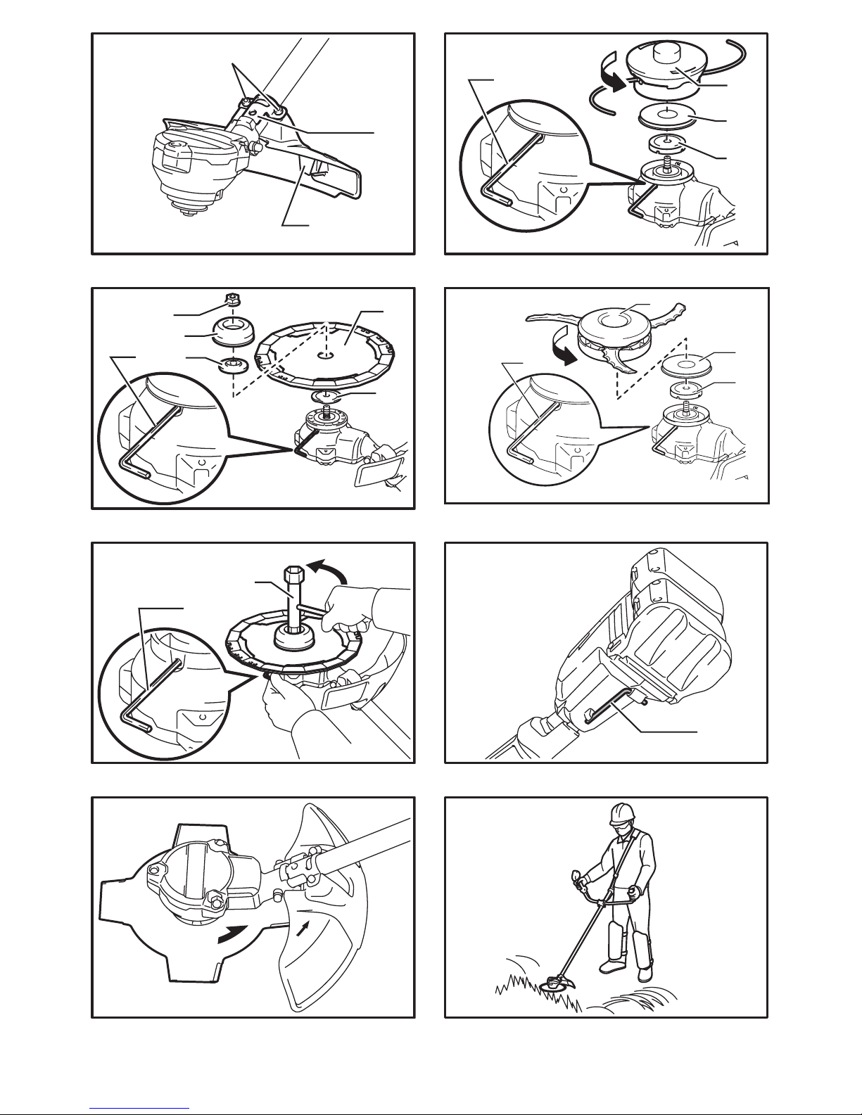
Putting into operation
1. Before assembling or adjusting the tool, remove
the battery cartridge.
2.
Before handling the cutter blade, wear protective gloves.
3. Before installing the battery cartridge, inspect the
tool for damages, loose screws/nuts or improper
assembly. Sharpen blunt cutter blade. If the cutter
blade is bent or damaged, replace it. Check all
control levers and switches for easy action. Clean
and dry the handles.
4. Never attempt to switch on the tool if it is damaged
or not fully assembled. Otherwise serious injury
may result.
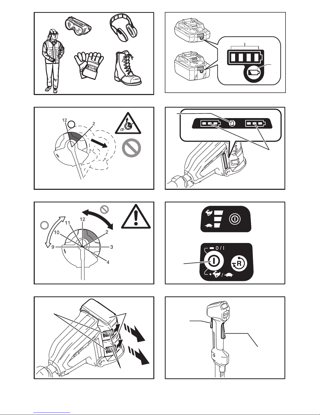
5. Adjust the shoulder harness and hand grip to suit
the operator's body size.
6. When inserting a battery cartridge, keep the
cutting attachment clear of your body and other
object, including the ground. It may rotate when
starting and may cause injury or damage to the
tool and/or property.
7. Remove any adjusting key, wrench or blade
cover before turning the tool on. An accessory left
attached to a rotating part of the tool may result in
personal injury.
OPERATION
1. In the event of an emergency, switch off the tool
immediately.
2. If you feel any unusual condition (e.g. noise,
vibration) during operation, switch off the tool and
remove the battery cartridge. Do not use the tool
until the cause is recognized and solved.
3. The cutting attachment continues to rotate for a
short period after turning the tool off. Don't rush to
contact the cutting attachment.
4. During operation, use the shoulder harness. Keep
the tool on your right side rmly.
5. Do not overreach. Keep proper footing and bal-
ance at all times. Watch for hidden obstacles
such as tree stumps, roots and ditches to avoid
stumbling.
6. Always be sure of your footing on slopes.
7. Walk, never run.
8. Never work on a ladder or tree to avoid loss of
control.
9. If the tool gets heavy impact or fall, check the
condition before continuing work. Check the con-
trols and safety devices for malfunction. If there is
any damage or doubt, ask our authorized service
center for the inspection and repair.
10. Do not touch the gear case. The gear case
becomes hot during operation.
11. Take a rest to prevent loss of control caused by
fatigue. We recommend taking a 10 to 20-minute
rest every hour.
12. When you leave the tool, even if it is a short time,
always remove the battery cartridge. The unat-
tended tool with the battery cartridge installed
may be used by unauthorized person and cause
serious accident.
13. If grass or branches get caught between the cut-
ting attachment and guard, always turn the tool off
and remove the battery cartridge before cleaning.
Otherwise the cutting attachment may rotate
unintentionally and cause serious injury.
14. Never touch moving hazardous parts before the
machine is disconnected from the mains and the
moving hazardous parts have come to a complete
stop.
15. If the cutting attachment hits stones or other
hard objects, immediately turn the tool off. Then
remove the battery cartridge and inspect the cut-
ting attachment.
16. Check the cutting attachment frequently during
operation for cracks or damages. Before the
inspection, remove the battery cartridge and wait
until the cutting attachment stops completely.
Replace damaged cutting attachment immedi-
ately, even if it has only supercial cracks.
17. Never cut above waist height.
18. Before starting the cutting operation, wait until the
cutting attachment reaches a constant speed after
turning the tool on.
19. When using metal blades, swing the tool evenly in
half-circle from right to left, like using a scythe.
20. Hold the tool by insulated gripping surfaces only,
because the cutter blade may contact hidden
wiring. Cutter blades contacting a "live" wire may
make exposed metal parts of the tool "live" and
could give the operator an electric shock.
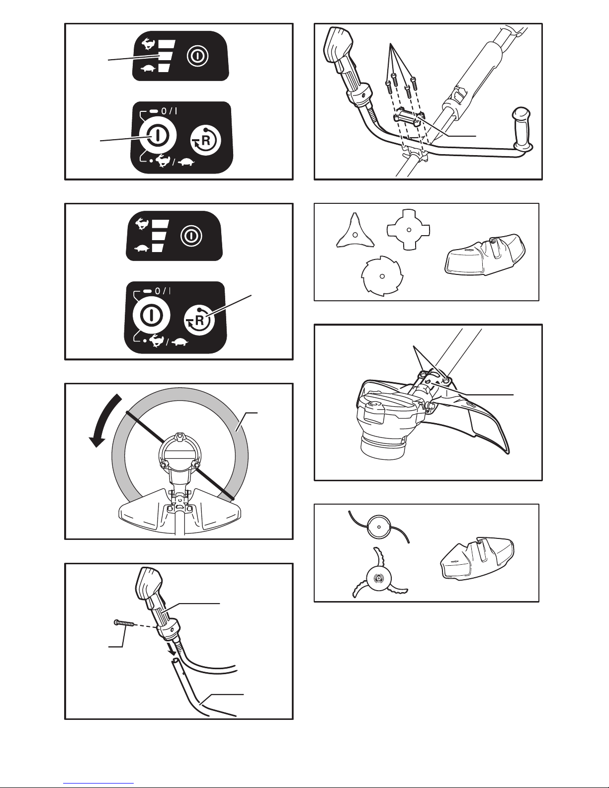
Cutting attachments
1. Use an applicable cutting attachment for the job in
hand.
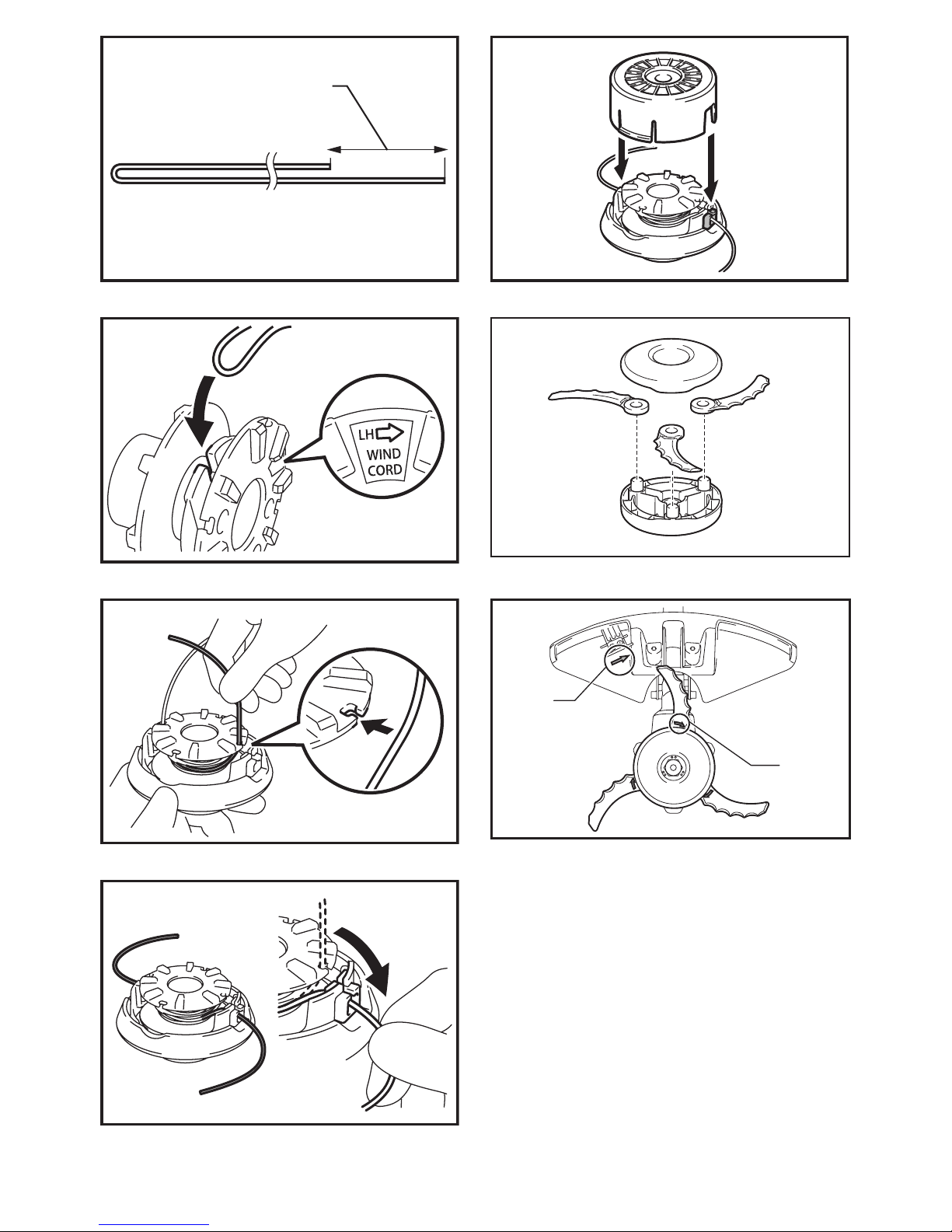
— Nylon cutting heads (string trimmer heads)
are suitable for trimming lawn grass.

10 ENGLISH
— Metal blades are suitable for cutting weeds,
high grasses, bushes, shrubs, underwood,
thicket, and the like.
— Never use other blades including metal
multi-piece pivoting chains and ail blades. It
may result in serious injury.
2. Always use the cutting attachment guard properly
suited for the cutting attachment used.
3. When using metal blades, avoid "kickback" and
always prepare for an accidental kickback. See
the section "Kickback".
4. When not in use, attach the blade cover onto the
blade. Remove the cover before operation.
Kickback (Blade thrust)
1. Kickback (blade thrust) is a sudden reaction to a
caught or bound cutting blade. Once it occurs, the
tool is thrown sideway or toward the operator at
great force and it may cause serious injury.
2. Kickback occurs particularly when applying the
blade segment between 12 and 2 o'clock to solids,
bushes and trees with 3 cm or larger diameter.
► Fig.2
3. To avoid kickback:
— Apply the segment between 8 and 11 o'clock.
— Never apply the segment between 12 and 2
o'clock.
— Never apply the segment between 11 and 12
o'clock and between 2 and 5 o'clock, unless
the operator is well trained and experienced
and does it at his/her own risk.
— Never use cutting blades close to solids,
such as fences, walls, tree trunks and
stones.
— Never use cutting blades vertically, for such
operations as edging and trimming hedges.
► Fig.3
Vibration
1. People with poor circulation who are exposed
to excessive vibration may experience injury to
blood vessels or the nervous system. Vibration
may cause the following symptoms to occur in the
ngers, hands or wrists: "Falling asleep" (numb-
ness), tingling, pain, stabbing sensation, alteration
of skin color or of the skin. If any of these symp-
toms occur, see a physician!
2. To reduce the risk of "white nger disease", keep
your hands warm during operation and well main-
tain the tool and accessories.
Transport
1. Before transporting the tool, turn it off and remove
the battery cartridge. Attach the cover to the cut-
ting blade.
2. When transporting the tool, carry it in a horizontal
position by holding the shaft.
3. When transporting the tool in a vehicle, properly
secure it to avoid turnover. Otherwise damage to
the tool and other baggage may result.
MAINTENANCE
1. Have your tool serviced by our authorized service
center, always using only genuine replacement
parts. Incorrect repair and poor maintenance can
shorten the life of the tool and increase the risk of
accidents.
2. Before doing any maintenance or repair work or
cleaning the tool, always turn it off and remove the
battery cartridge.
3. Always wear protective gloves when handling the
cutting blade.
4. Always clean dust and dirt off the tool. Never use
gasoline, benzine, thinner, alcohol or the like for
the purpose. Discoloration, deformation or cracks
of the plastic components may result.
5. After each use, tighten all screws and nuts.
6. Do not attempt any maintenance or repair not
described in the instruction manual. Ask our
authorized service center for such work.
7. Always use our genuine spare parts and acces-
sories only. Using parts or accessories supplied
by a third party may result in the tool breakdown,
property damage and/or serious injury.
8. Request our authorized service center to inspect
and maintain the tool at regular interval.
Storage
1. Before storing the tool, perform full cleaning and
maintenance. Remove the battery cartridge.
Attach the cover to the cutting blade.
2. Store the tool in a dry and high or locked location
out of reach of children.
3. Do not prop the tool against something, such as a
wall. Otherwise it may fall suddenly and cause an
injury.
First aid
1. Always have a rst-aid kit close by. Immediately
replace any item taken from the rst aid kit.
2. When asking for help, give the following
information:
— Place of the accident
— What happened
— Number of injured persons
— Nature of the injury
— Your name
SAVE THESE INSTRUCTIONS.
WARNING: DO NOT let comfort or famil-
iarity with product (gained from repeated
use) replace strict adherence to safety
rules for the subject product. MISUSE or
failure to follow the safety rules stated in
this instruction manual may cause serious
personal injury.

11 ENGLISH
Important safety instructions for
battery cartridge
1. Before using battery cartridge, read all instruc-
tions and cautionary markings on (1) battery
charger, (2) battery, and (3) product using
battery.
2. Do not disassemble battery cartridge.
3. If operating time has become excessively
shorter, stop operating immediately. It may
result in a risk of overheating, possible burns
and even an explosion.
4. If electrolyte gets into your eyes, rinse them
out with clear water and seek medical atten-
tion right away. It may result in loss of your
eyesight.
5. Do not short the battery cartridge:
(1) Do not touch the terminals with any con-
ductive material.
(2) Avoid storing battery cartridge in a con-
tainer with other metal objects such as
nails, coins, etc.
(3) Do not expose battery cartridge to water
or rain.
A battery short can cause a large current
ow, overheating, possible burns and even a
breakdown.
6. Do not store the tool and battery cartridge in
locations where the temperature may reach or
exceed 50 °C (122 °F).
7. Do not incinerate the battery cartridge even if
it is severely damaged or is completely worn
out. The battery cartridge can explode in a re.
8. Be careful not to drop or strike battery.
9. Do not use a damaged battery.
10. The contained lithium-ion batteries are subject
to the Dangerous Goods Legislation require-
ments.
For commercial transports e.g. by third parties,
forwarding agents, special requirement on pack-
aging and labeling must be observed.
For preparation of the item being shipped, consult-
ing an expert for hazardous material is required.
Please also observe possibly more detailed
national regulations.
Tape or mask off open contacts and pack up the
battery in such a manner that it cannot move
around in the packaging.
11. Follow your local regulations relating to dis-
posal of battery.
12. Use the batteries only with the products
specied by Makita. Installing the batteries to
non-compliant products may result in a re, exces-
sive heat, explosion, or leak of electrolyte.
SAVE THESE INSTRUCTIONS.
CAUTION: Only use genuine Makita batteries.
Use of non-genuine Makita batteries, or batteries that
have been altered, may result in the battery bursting
causing res, personal injury and damage. It will
also void the Makita warranty for the Makita tool and
charger.
Tips for maintaining maximum
battery life
1. Charge the battery cartridge before completely
discharged. Always stop tool operation and
charge the battery cartridge when you notice
less tool power.
2. Never recharge a fully charged battery car-
tridge. Overcharging shortens the battery
service life.
3. Charge the battery cartridge with room tem-
perature at 10 °C - 40 °C (50 °F - 104 °F). Let
a hot battery cartridge cool down before
charging it.
4. Charge the battery cartridge if you do not use
it for a long period (more than six months).

12 ENGLISH
PARTS DESCRIPTION
1
2
3
4
5
6
7
8
9
10
11
12
Battery cartridge
Hanger (suspension point)
Lock-off lever
Switch trigger
Grip
Protector (cutting tool guard)
Cutting tool
Power lamp
Speed indicator
Reverse button
Main power button
Shoulder harness
1
2
3
4
5
6
7
8
9
10
11
12

13 ENGLISH
FUNCTIONAL DESCRIPTION
WARNING:
• Always be sure that the tool is switched off
and the battery cartridge is removed before
adjusting or checking function on the tool.
Failure to switch off and remove the battery
cartridge may result in serious personal injury
from accidental start-up.
Installing or removing battery cartridge
CAUTION:
• Always switch off the tool before installing or
removing of the battery cartridge.
• Hold the tool and the battery cartridge rmly
when installing or removing battery car-
tridge. Failure to hold the tool and the battery
cartridge rmly may cause them to slip off your
hands and result in damage to the tool and
battery cartridge and a personal injury.
► Fig.4: 1. Red indicator 2. Button 3. Battery cartridge
To remove the battery cartridge, slide it from the tool
while sliding the button on the front of the cartridge.
To install the battery cartridge, align the tongue on the
battery cartridge with the groove in the housing and slip
it into place. Insert it all the way until it locks in place
with a little click. If you can see the red indicator on the
upper side of the button, it is not locked completely.
CAUTION:
• Always install the battery cartridge fully until the
red indicator cannot be seen. If not, it may acci-
dentally fall out of the tool, causing injury to you
or someone around you.
• Do not install the battery cartridge forcibly. If the
cartridge does not slide in easily, it is not being
inserted correctly.
NOTE:
• The tool does not work with only one battery
cartridge.
Indicating the remaining battery capacity
Only for battery cartridges with the indicator
► Fig.5: 1. Indicator lamps 2. Check button
Press the check button on the battery cartridge to indi-
cate the remaining battery capacity. The indicator lamps
light up for a few seconds.
Indicator lamps Remaining
capacity
Lighted Off Blinking
75% to 100%
50% to 75%
25% to 50%
Indicator lamps Remaining
capacity
Lighted Off Blinking
0% to 25%
Charge the
battery.
The battery
may have
malfunctioned.
NOTE: Depending on the conditions of use and the
ambient temperature, the indication may differ slightly
from the actual capacity.
Tool / battery protection system
The tool is equipped with a tool/battery protection sys-
tem. This system automatically cuts off power to the
motor to extend tool and battery life.
The tool will automatically stop during operation if the
tool or battery is placed under one of the following con-
ditions. In some conditions, the indicators light up.
Overload protection
On Off Blinking
If the tool is overloaded by entangled weeds or other
debris, the tool stops automatically, and all of the speed
indicators blink. In this situation, turn the tool off and
stop the application that caused the tool to become
overloaded. Then turn the tool on to restart.
Overheat protection for tool
On Off Blinking
When the tool is overheated, the tool stops automat-
ically, and all of the speed indicators and the battery
indicator blink about 60 seconds. In this situation, let the
tool cool down before turning the tool on again.
Overdischarge protection
When the battery capacity becomes low, the tool stops
automatically. If the tool does not operate even when
the switches are operated, remove the batteries from
the tool and charge the batteries.

14 ENGLISH
Remaining battery capacity
indication
(Country specic)
► Fig.6: 1. Battery indicator 2. CHECK button
Press the check button to make the battery indicators
show the remaining battery capacities. The battery
indicators correspond to each battery.
Remaining battery capacity indication
Battery indicator status
Remaining battery capacity
50 % - 100 %
20 % - 50 %
0 % - 20 %
Charge the battery
On Off Blinking
Power switch action
WARNING:
• Before inserting the battery cartridge into
the tool, always check to see that the switch
trigger actuates properly and returns to the
"OFF" position when released. Operating a
tool with a switch that does not actuate properly
can lead to loss of control and serious personal
injury.
► Fig.7: 1. Main power button
Press and hold the main power button for some sec-
onds to turn on the tool.
To turn off the tool, press and hold the main power
button again.
► Fig.8: 1. Lock-off lever 2. Switch trigger
To prevent the switch trigger from being accidentally
pulled, a lock-off lever is provided.
To start the tool, grasp the right grip (the lock-off lever is
released by the grasp) and then pull the switch trigger.
To stop the tool, release the switch trigger.
NOTE:
• The tool is automatically turned off after the tool
is left one minute without any operations.
Speed adjusting
► Fig.9: 1. Main power button 2. Speed indicator
You can adjust the tool speed by tapping the main
power button.
Each time you tap the main power button, one of the
speed indicator lights up in order of Turtle( ), middle,
Rabbit( ).
is for low speed and for high speed , and the
middle indicator for middle speed.
Reverse button for debris removal
WARNING:
• Switch off the tool and remove the battery
cartridge before you remove entangled
weeds or debris which the reverse rotation
function can not remove. Failure to switch off
and remove the battery cartridge may result in
serious personal injury from accidental start-up.
► Fig.10: 1. Reverse button
This tool has a reverse button to change the direction of
rotation. It is only for removing weeds and debris entan-
gled in the tool.
To reverse the rotation, tap the reverse button and pull
the trigger when the tool’s head is stopped. The power
lamp starts blinking, and the tool's head rotates in
reverse direction when you pull the switch trigger.
To return to regular rotation, release the trigger and wait
until the tool's head stops.
NOTE:
• During the reverse rotation, the tool operates
only for a short period of time and then automat-
ically stops.
• Once the tool is stopped, the rotation returns to
regular direction when you start the tool again.
• If you tap the reverse button while the tool's
head is still rotating, the tool comes to stop and
to be ready for reverse rotation.
Nylon cutting head (optional
accessory)
NOTICE:
• The bump feed will not operate properly if the
head is not rotating.
► Fig.11: 1. Most effective cutting area
The nylon cutting head is a dual string trimmer head
provided with a bump & feed mechanism.
To cause the nylon cord to feed out, the cutting head
should be bumped against the ground while rotating.
NOTE: If the nylon cord does not feed out while
bumping the head, rewind/replace the nylon cord
by following the procedures described under
“Maintenance”.
ASSEMBLY
WARNING:
• Always be sure that the tool is switched
off and battery cartridge is removed before
carrying out any work on the tool. Failure to
switch off and remove the battery cartridge may
result in serious personal injury from accidental
start-up.
• Never start the tool unless it is completely
assembled. Operation of the tool in a partially
assembled state may result in serious personal
injury from accidental start-up.

15 ENGLISH
Installing the handle
► Fig.12: 1. Grip 2. Handle 3. Screw
Insert the shaft of the handle into the grip. Align the
screw hole in the grip with the one in the shaft. Tighten
the screw securely.
► Fig.13: 1. Handle clamp 2. Screw
Place handle between handle clamp and handle holder.
Adjust the handle to an angle that provides a comfortable work-
ing position and then secure by rmly hand-tightening knob.
Installing the guard
WARNING:
• Never use the tool without the guard illus-
trated in place. Failure to do so can cause
serious personal injury.
• Always use the tool with the approved combina-
tion of the safety equipments. Otherwise contact
with a cutting tool may cause serious injury.
• Permitted combination for the cutting tool and
the guard may differ from country to country.
Follow your region's regulations.
For metal blade
► Fig.14
► Fig.15: 1. Clamp 2. Bolt
For nylon cutting head or plastic blade
CAUTION:
• Take care not to injure yourself on the cutter
for cutting the nylon cord when installing nylon
cutting head or plastic blade.
► Fig.16
► Fig.17: 1. Cutter 2. Clamp 3. Bolt
Align the clamp on the pipe with the protector. And
tighten them with bolts.
Installing the metal blade (optional
accessory)
WARNING:
• The outside diameter of the metal blade must
be 230 mm. Never use any blade exceeding
230 mm in outside diameter.
CAUTION:
• The metal blade must be well polished, free of
cracks or breakage. Polish or replace the metal
blade every three hours of operation.
•
Always wear gloves when handling the metal blade.
• Always attach the blade cover when the tool is
not in use or is being transported.
•
The metal blade-fastening nut (with spring washer)
wears out in course of time. If there appears any wear
or deformation on the spring washer, replace the nut.
Ask your local authorized service center to order it.
• Replace the cup in case of crack or breakage
due to attrition.
NOTICE:
• Be sure to use genuine Makita metal blade.
Turn the tool upside down so that you can replace the
metal blade easily.
► Fig.18: 1. Hex wrench 2. Nut 3. Cup 4. Clamp
washer 5. Metal blade 6. Receive washer
Mount the metal blade onto the shaft so that the guide
of the receive washer ts in the arbor hole in the metal
blade. Install the clamp washer and secure the metal
blade with the hex nut with 13 to 23 Nm of tightening
torque during holding the receive washer with hex
wrench.
► Fig.19: 1. Hex wrench 2. Box driver 3. Tighten
To dismount the metal blade, insert the hex wrench
through the hole on the protector cover and the gear
case. Rotate the receive washer until it is locked with
the hex wrench. Loosen the hex nut (left-hand thread)
with the socket wrench and remove the nut, clamp
washer and hex wrench.
► Fig.20
Make sure that the blade is the left way up.
Installing nylon cutting head or
plastic blade (optional accessory)
CAUTION:
• If the nylon cutting head / plastic blade acci-
dentally impacts a rock or hard object during
operation, stop the tool and inspect for any
damage. If the nylon cutting head / plastic
blade is damaged, replace it immediately.
Use of a damaged cutting tool could result in
serious personal injury.
NOTICE:
• Be sure to use genuine Makita nylon cutting head
/ plastic blade.
Turn the tool upside down so that you can replace the
nylon cutting head easily.
► Fig.21: 1. Nylon cutting head 2. Metal guard
3. Receive washer 4. Hex wrench 5. Tighten
► Fig.22: 1. Plastic blade 2. Metal guard 3. Receive
washer 4. Hex wrench 5. Tighten
Insert the hex wrench through the hole on the motor
housing and rotate the receive washer until it is locked
with the hex wrench. Place the nylon cutting head /
plastic blade onto the threaded spindle directly and
tighten it by turning it counterclockwise. Remove the
hex wrench.
To remove the nylon cutting head / plastic blade, turn
it clockwise while holding the receive washer with the
hex wrench.
Hex wrench storage
► Fig.23: 1. Hex wrench
When not in use, store the hex wrench as shown in the
gure to keep it from being lost.

16 ENGLISH
OPERATION
Correct handling of tool
WARNING:
• Be extremely careful to maintain control of
the tool at all times. Do not allow the tool to
be deected toward you or anyone in the
work vicinity. Failure to keep control of the tool
could result in serious injury to the bystander
and the operator.
Correct posture
WARNING:
• Always hold the both grips rmly and posi-
tion the tool on your right-hand side so that
the shaft of the left handle is always in front
of your body. Correct positioning of the tool
allows for maximum control and will reduce
the risk of serious personal injury caused by
kickback.
► Fig.24
Fit the shoulder harness and hang the tool rmly on
your right side so that the shaft of the left handle is
always ahead of you.
Attachment of shoulder harness
► Fig.25: 1. Buckle 2. Hook
Wear the shoulder harness on your left shoulder. Make
sure that the buckle cannot be taken off with pulling it
off. Hang the tool as shown.
► Fig.26: 1. Buckle
The buckle is provided with a means of quick release.
Simply squeeze the sides of the buckle to release the
tool.
Adjustment of the hanger position
and shoulder harness
To change the hanger position, loosen the xing screw
on the hanger with the supplied wrench and then move
the hanger and the cushion. The cushion can be moved
easily by twisting it.
MAINTENANCE
WARNING:
• Always be sure that the tool is switched
off and battery cartridge is removed before
attempting to perform inspection or main-
tenance on the tool. Failure to switch off and
remove the battery cartridge may result in seri-
ous personal injury from accidental start-up.
NOTICE:
Never use gasoline, benzine, thinner, alcohol or
the like. Discoloration, deformation or cracks may
result.
Replacing the nylon cord
WARNING: Use nylon cord with diameter
specied in “SPECIFICATIONS” only. Never use
heavier line, metal wire, rope or the like. Use rec-
ommended nylon cord only, otherwise it may cause
damage to the tool and result in serious personal
injury.
WARNING: Make sure that the cover of the
nylon cutting head is secured to the housing
properly as described below. Failure to properly
secure the cover may cause the nylon cutting head to
y apart resulting in serious personal injury.
For 95-M10L
1. Press on the housing latches inward to lift off the
cover, then remove the spool.
► Fig.27: 1. Latch 2. Cover
2. Prepare approximately 3 m (9 ft) of new nylon
cord. Fold the new nylon cord with one end become
approximately 80 mm (3-1/8″) longer than the other
end. Then hook the new nylon cord into the notch in the
center of the spool.
Wind both ends rmly around the spool in the direction
of the head rotation (left-hand direction indicated by LH
on the side of the spool).
► Fig.28: 1. Spool
3. Wind all but about 100 mm (3 - 15/16″) of the
cords, leaving the ends temporarily hooked through a
notch on the side of the spool.
► Fig.29
4. Mount the spool in the housing so that the grooves
and protrusions on the spool match up with those in the
housing. Keep the side with letters on the spool visible
on the top. Now, unhook the ends of the cord from their
temporary position and feed the cords through the
eyelets to come out of the housing.
► Fig.30: 1. Spool 2. Housing 3. Eyelet
5. Align the protrusion on the underside of the cover
with the slots of the eyelets. Then push the cover rmly
onto the housing to secure it.
► Fig.31
For B&F ECO4L
► Fig.32
Take off cover from housing, pressing two latches which
are slotted section oppositely on side of housing.
► Fig.33: 1. 80-100 mm
Cut a nylon line in 3 m. Fold the cutting line in two
halves, leave one of half longer 80-100 mm than
another.
► Fig.34
Hook the middle of the new nylon cord to the notch
located at the center of the spool between the 2 chan-
nels provided for the nylon cord.
Wind both ends rmly around the spool in the direction
marked on the head for left hand direction indicated by
LH.

17 ENGLISH
► Fig.35
Wind all but about 100 mm of the cords, leaving the
ends temporarily hooked through a notch on the side of
the spool.
► Fig.36
Mount the spool on the cover so that the grooves and
protrusions on the spool match up with those on the
cover. Now, unhook the ends of the cord from their tem-
porary position and feed the cords through the eyelets
to come out of the cover.
► Fig.37
Align the protrusion on the underside of the cover with
the slots of the eyelets. Then push the cover rmly onto
the housing to secure it. Make sure the latches fully
spread in the cover.
Replacing the plastic blade
Replace the blade if it is worn out or broken.
► Fig.38
When installing the plastic blade, align the direction of
the arrow on the blade with that of the protector.
► Fig.39: 1. Arrow on the protector 2. Arrow on the
blade
To maintain product SAFETY and RELIABILITY,
repairs, any other maintenance or adjustment should
be performed by Makita Authorized or Factory Service
Centers, always using Makita replacement parts.

18 ENGLISH
TROUBLE SHOOTING
Before asking for repairs, conduct your own inspection rst. If you nd a problem that is not explained in the manual,
do not attempt to dismantle the tool. Instead, ask Makita Authorized Service Centers, always using Makita replace-
ment parts for repairs.
Tighten the nut properly as described
in this manual.
Recharge the battery cartridge. If recharging
is not effective, replace battery cartridge.
Recharge the battery cartridge. If recharging
is not effective, replace battery cartridge.
Cutter blade fastening nut is loose.
Cutter blade is fastened improperly.
The cutter blade is bent,
cracked or worn.
Malfunction status
Motor does not run.
Cause
Battery cartridges are not installed.
Battery problem (under voltage)
Rotation is in reverse.
Overheating.
Battery power is dropping.
Electric or electronic malfunction.
Action
Install the battery cartridges.
Remove the foreign object.
Motor stops running after a little use.
It does not reach maximum RPM.
Cutting tool does not rotate:
stop the machine immediately!
Abnormal vibration:
stop the machine immediately!
Cutting tool and motor cannot stop:
Remove the battery immediately!
Cutter blade fastening nut is loose. Tighten the nut properly as described
in this manual.
The cutter blade is bent. Replace the cutter blade.
Replace the cutter blade.
The drive system does not work
correctly.
Battery's charge level is low.
Battery is installed improperly.
The drive system does not work
correctly.
Foreign object such as a branch is
jammed between the guard and
the nylon cutting head.
The drive system does not work
correctly.
One end of the nylon cord has
been broken.
The drive system does not work
correctly.
Recharge the battery cartridge. If recharging
is not effective, replace battery cartridge.
Ask your local authorized service center for
repair.
Ask your local authorized service center for
repair.
Change the direction of ratation with the
reversing switch.
Stop using of tool to allow it to cool down.
Install the battery cartridge as described in
this manual.
Ask your local authorized service center for
repair.
Ask your local authorized service center for
repair.
Bump the nylon cutting head against the
ground while it is rotating to cause the cord
to feed.
Remove the battery cartridge and ask your
local authorized service center for repair.

19 ENGLISH
OPTIONAL
ACCESSORIES
CAUTION:
• These accessories or attachments are recom-
mended for use with your Makita tool specied
in this manual. The use of any other accessories
or attachments might present a risk of injury to
persons. Only use accessory or attachment for
its stated purpose.
If you need any assistance for more details regard-
ing these accessories, ask your local Makita Service
Center.
• Cutter blade
• Nylon cutting head
• Nylon cord (cutting line)
• Plastic blade
• Protector assembly for nylon cutting
• Protector assembly for cutter blade
• Makita genuine battery and charger
NOTE:
• Some items in the list may be included in the
tool package as standard accessories. They
may differ from country to country.

20 УКРАЇНСЬКА
УКРАЇНСЬКА (Оригінальні вказівки)
ТЕХНІЧНІ ХАРАКТЕРИСТИКИ
Модель DUR365U
Тип ручки Велосипедна ручка
Швидкість без навантаження 3500 / 5300 / 6500 хв-1
Загальна довжина (із ріжучим інструментом)
1754 мм
Діаметр нейлонового шнура 2,0 – 2,4 мм
Застосовний ріжучий інструмент
(залежить від країни)
Металева ріжуча пластина
(Н/Д 195150-5)
Ріжуча головка з нейлоно-
вим шнуром
(Н/Д 197296-3/ 198892-0/
198893-8)
Пластикова ріжуча пластина
(Н/Д 198383-1)
Діаметр різання 230 мм 350 мм 255 мм
Номінальна напруга 36 В пост. струму
Стандартна касета з акумулятором BL1815N / BL1820 / BL1820B BL1830 / BL1830B / BL1840 / BL1840B /
BL1850 / BL1850B / BL1860B
Вага нетто (із металевою ріжучою пластиною)
4,7 кг 5,2 кг
• Через те, що ми не припиняємо програми досліджень і розвитку, наведені тут технічні характеристики
можуть бути змінені без попередження.
• Технічні характеристики приладу та касета з акумулятором можуть відрізнятися в різних країнах.
• Вага разом з касетою з акумулятором відповідно до EPTA-Procedure 01/2003
Шум Середній рівень
звукового тиску
Середній рівень акустичної потужності Відповідний
стандарт
LPA (дБ (А)) LWA (дБ (A)) Похибка K (дБ (A))
Металева ріжуча пластина 75 86 0,4 2000/14/EC
Пластикова ріжуча пластина 73 84,4 1,0
Ріжуча головка з нейлоновим шнуром 77 90 2,2
• Навіть якщо наведений вище рівень звукового тиску менше або дорівнює 80 дБ (A), рівень безпосередньо у
місці виконання роботи може перевищувати 80 дБ (A). Використовуйте засоби захисту органів слуху.
Вібрація Ліва рука Права рука Відповідний
стандарт
ah (м/с2)
Похибка K (м/с2)
ah (м/с2)
Похибка K (м/с2)
Металева ріжуча пластина ≤ 2,5 1,5 ≤ 2,5 1,5 EN786
Пластикова ріжуча пластина ≤ 2,5 1,5 ≤ 2,5 1,5
Ріжуча головка з нейлоновим шнуром ≤ 2,5 1,5 ≤ 2,5 1,5
ПРИМІТКА: Заявлене значення вібрації було
виміряно у відповідності до стандартних методів
тестування та може використовуватися для порів-
няння одного інструмента з іншим.
ПРИМІТКА: Заявлене значення вібрації може
також використовуватися для попередньої оцінки
впливу.
ПОПЕРЕДЖЕННЯ: Залежно від умов вико-
ристання вібрація під час фактичної роботи інстру-
мента може відрізнятися від заявленого значення
вібрації.
ПОПЕРЕДЖЕННЯ: Забезпечте належні
запобіжні заходи для захисту оператора, що відпо-
відатимуть умовам використання інструмента (слід
брати до уваги всі складові робочого циклу, такі як
час, коли інструмент вимкнено та коли він починає
працювати на холостому ході під час запуску).
Символи
Далі наведені символи, які застосовуються для
позначення обладнання. Перед користуванням
переконайтеся, що Ви розумієте їхнє значення.
Будьте особливо уважні та обережні!
Читайте інструкцію з експлуатації.
Небезпека; пам’ятайте, що предмети
можуть відскочити.
Відстань між інструментом і людьми, що
знаходяться поблизу, повинна становити
не менше 15 метрів.
Слідкуйте за тим, щоб сторонні особи
знаходилися на небезпечній відстані.
Other manuals for DUR365U
11
Table of contents
Languages:
Other Makita Trimmer manuals

Makita
Makita UR006G User manual

Makita
Makita DRT50 User manual

Makita
Makita UH013G User manual

Makita
Makita UR016G User manual

Makita
Makita 3708 User manual

Makita
Makita DUR190U User manual

Makita
Makita DUR192L User manual

Makita
Makita RT0700C Setup guide

Makita
Makita EBH252U User guide

Makita
Makita DUH481 User manual

Makita
Makita DUR187U User manual

Makita
Makita EM4250 User manual

Makita
Makita XRU09PT User manual

Makita
Makita DUN600L User manual

Makita
Makita 4050, 4850, 5550, 6350 Manual

Makita
Makita UR3500 User manual

Makita
Makita ER2600L Instruction Manual

Makita
Makita UH4261 User manual

Makita
Makita ER2650LH User manual

Makita
Makita UH4570 User manual