Malabar 150-30H User manual

MALABAR
INTERNATIONAL
Date: February 18, 2011
OWNER’S MANUAL FOR MALABAR MODEL
AIRCRAFT MAINTENANCE & SUPPORT EQUIPMENT
150-30H
1 LITER O-C FLUID GUN DISPENSER
* GENERAL DESCRIPTION
* OPERATION
* SERVICE
* PARTS BREAKDOWN
For Service & Spare
Parts, Please Contact: Malabar International
220 W. Los Angeles Avenue
Simi Valley, California 93065
Phone: (805) 581-0116
Fax: (805) 584-1624
Web site: http://www.malabar.com
OVER 65 YEARS OF SERVICE & EXPERIENCE
©2002 Malabar International. All rights reserved. Permission to reproduce all or part of this material must be obtained from Malabar International.
READ
AND
SAVE
THIS
INSTRUCTION
MANUAL

- 1 -
GENERAL DESCRIPTION, OPERATION, SERVICE AND PARTS BREAKDOWN
MALABAR MODEL 150-30H
1 LITER O-C FLUID GUN DISPENSER
CAUTION: AIRCRAFT MANUFACTURER’S SPECIFICATION AND INSTRUC-
TIONS MUST BE FOLLOWED IN THE EVENT OF CONTRADICTION
BETWEEN AIRCRAFT MANUFACTURER’S SPECIFICATIONS AND
MALABAR’S AIRCRAFT MANUFACTURER’S SPECIFICATIONS WILL
PREVAIL.
SPECIFICATIONS:
Fluid---------------------------------------------------------------------------------------------- Engine and IDG oil
Fluid Capacity --------------------------------------------------------------------------------- 1.06 quarts (1 liter)
Pump Outlet Pressure----------------------------------------------------------------------- 40 psig (276 kg/sq cm)
Volume Per Stroke --------------------------------------------------------------------------- 4 cubic inches (66 cc)
Hose Length ----------------------------------------------------------------------------------- 74 inches (1880 mm)
Net Weight (empty) -------------------------------------------------------------------------- 6.5 lbs (2.9 kg)
Filter Rating ------------------------------------------------------------------------------------ 3 micron nominal
GENERAL DESCRIPTION:
The Malabar Model 150-30H is a one liter original container fluid gun dispenser used to service various
commercial aircraft. The O-C Fluid Gun Dispenser consists of a hand pump assembly, filter assembly and
a fluid delivery hose with a coupling.
PREPARATION FOR USE:
1. Attach the hose assembly to the gun. Avoid over tightening the swivel nut.
2. The two latches attached to the clamp bars may require adjustment. Loosen the four screws, washers
and self-locking nuts and adjust latches to fit oil can before tightening screws.
OPERATION:
1. Slide piercer rod fully up and latch oil can to gun. Check the fluid specification and brand for
compatibility with the aircraft system.
2. Strike piercer handle firmly using palm of hand or rubber mallet to drive piercer through top of oil can.
Assure piercer is firmly placed in oil can.
CAUTION: TO PREVENT DAMAGE TO THE PIERCER ROD OR PIERCER HANDLE,
DO NOT USE ANY TOOL OTHER THAN A RUBBER MALLET.
3. Open the bleed screw on the sight gage (one turn only) and carefully pump the gun to prime and
eliminate any air bubbles. Close bleed screw.
CAUTION: AIR PUMPED IN WITH OIL MAY CAUSE FALSE LEVEL READINGS IN
AIRCRAFT SYSTEMS AS THE AIR EVENTUALLY BUBBLES OFF AND
THE LEVEL DROPS.
4. Remove dust plug from hose end coupling and connect hose end coupling to the aircraft service

- 2 -
point.
5. Use full steady pump strokes when operating pump assembly during replenishing. Stop pumping oil
when can is empty or air bubbles are detected in sight gage. Reprime gun when changing cans.
6. When finished, disconnect the hose end coupling from the aircraft service point. Replace the dust
plug and store the gun in a dry dust free location.
7. When gun is stored, it is advisable to keep oil can latched to the gun to prevent contamination and oil
mess.
SERVICING:
The frequency of filter change depends on operating conditions. Generally, changes should be made
every 3-4 months or sooner if more than normal resistance is felt on the pumping stroke at low pressure.
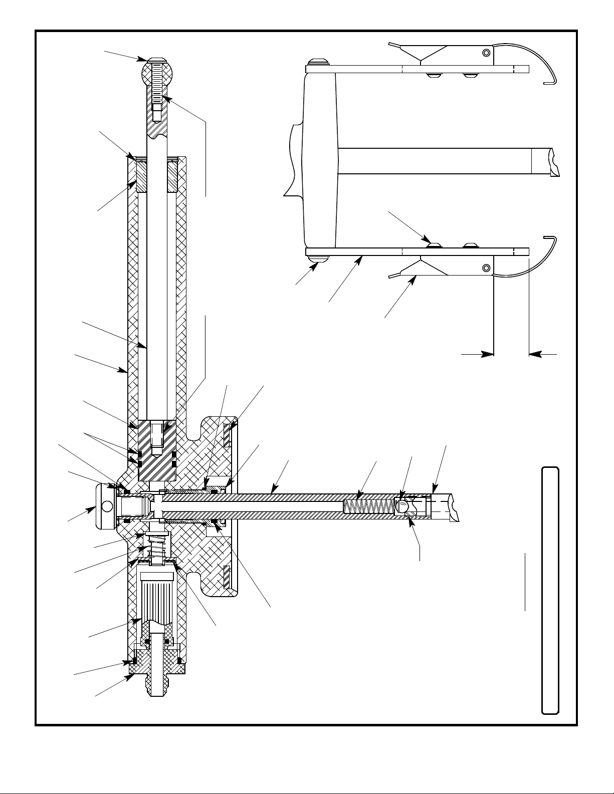
Refer to figure 1A, item 43 to change filter element.
REPAIR AND REPLACEMENT:
No definite time schedule can be established for the overhaul of the O-C fluid gun dispenser assembly for
the replacement of the various moving parts. The number of times the pump assembly is operated
materially affects the life of the working parts. The moving piston seals (figure 1A, item 20) and piercer
rod seals (figure 1A, item 22) are normally the first to wear. This is usually indicated by leakage of fluid
past the piston rod (figure 1A, item 2) or the piercer rod (figure 1A, item 12). It is advisable to change
piston seals (figure 1A, item 20) and piercer rod seals (figure 1A, item 22) immediately if leakage is
discovered. Regardless of apparent condition, replace all parts marked with (♦). A repair parts kit (P/N
150-6HPK) which contains all of the parts marked with (♦) is available and recommended to keep on
hand at your facility. Coat all o-rings with petroleum jelly prior to assembly. Clean all metal parts with
solvent and dry with compressed air. Lubricate all threads. Refer to sheet 6 for the complete list of parts
contained in the repair parts kit.
5/8 RECOMMENDED
FOR CAN
ADJUSTMENT
6
- 3 -
79
♦21
♦43
♦30
♦22
♦36
40
8
11
20 ♦
22 ♦
12
5
FIGURE 1A
APPLY LOCTITE
#609 ON THREADS
HOSE ASSEMBLY
NOT SHOWN FOR
CLARITY
MODEL 150-30H UNIT ASSEMBLY
31 ♦
33 ♦
13
APPLY LOCTITE #609
ON THREADS
1
29
2
24
27
19 ♦
10 ♦
23
37
♦PART OF REPAIR PARTS KIT
25
26
39
41
4
49
14
46 ♦
- 4 -
♦42
47
45
44
B
B
17
38
16
38
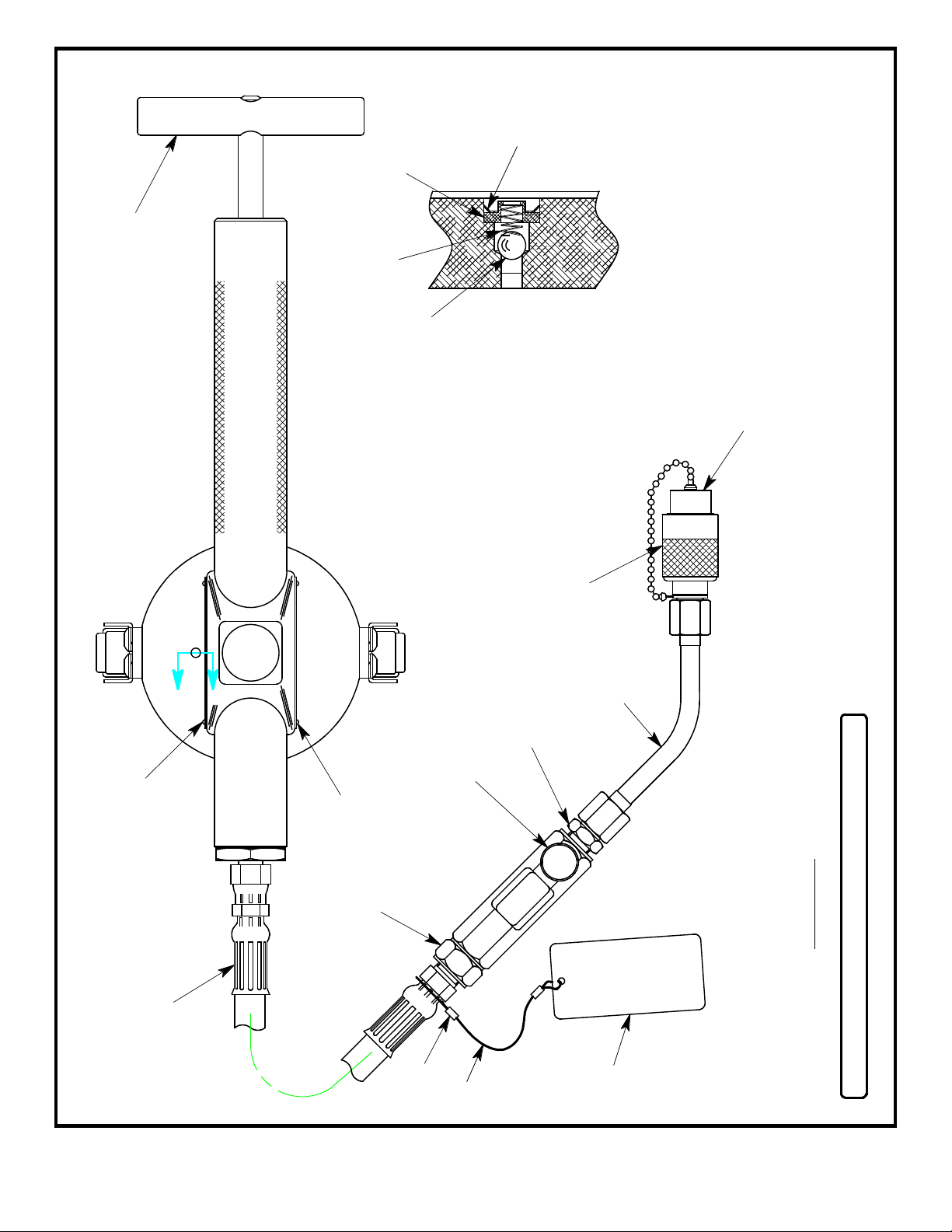
MODEL 150-30H UNIT ASSEMBLY
FIGURE 1B
ENGINE AND
IDG OIL
174468
18 48
28
♦34
♦PART OF REPAIR PARTS KIT
3
♦32 15
VIEW B-B ENLARGED
50
35 ♦

1 1 174493-2
2 1 174405
3 1 174406
4 2 174407
5 1 174459
6 1 174494
7 1 174412
8 1 174413
9 1 174414
10 1 174487
11 1 174416
12 1 174474
13 1 174461
14 1 174419
15 1 174420
16 1 174421
17 1 174467
18 1 174468
19 155934-019
20 255934-116
21 155934-120
22 255934-114
23 1 326-009
24 4 326-010
25 4 326-020
26 4 355-025
27 4 363-001
28 1 721-004
29 1 410-017
30 1 495-035
31 1 495-036
32 1 495-037
33 1 412-002
34 1 412-004
35 1 380-005
36 1 380-004
37 155926-100
38 8 393-004
39 4 362-045
40 1 369-002
41 2 491-056
42 1 174445
43 1PF55996
44 1 491-027
45 2 491-028
46 155934-904
47 1 174488
48 1PF55817
49 1 736-013
50 1PF55987
PUMP BODY MACHINE
PISTON ROD
HANDLE
CLAMP BAR
BEARING BOLT ASSEMBLY
PISTON
ADAPTER FITTING
VALVE POPPET
POPPET GUIDE
CAN SEAL
PIERCER HANDLE
PIERCER ROD
PIERCER
BLEED SCREW
SPRING SUPPORT
PLACARD
PLACARD, ENGINE AND IDG OIL
PLACARD, ENGINE AND IDG OIL
O-RING
O-RING
O-RING
O-RING
BHCS, 1/4-20 x 1" LG
BHCS, 1/4-20 x 5/8 LG
BHCS, 10-24 x 1/2 LG
HEX LOCKNUT, 10-24
SPLIT LOCKWASHER, 1/4
CONNECTOR, 3/8 37° x1/4 MPT
BRONZE BEARING
SPRING
SPRING
SPRING
BALL, CHROME, 5/16 DIA
BALL, CHROME, 1/4 DIA
RETAINING RING, PUSH ON
RETAINING RING, PUSH ON
RETAINING RING, PUSH ON
DRIVE SCREW, #2 x 3/16 LG
FLAT WASHER, #10
NYLON FLAT WASHER
LATCH
HOSE ASSEMBLY
FILTER ELEMENT
CABLE, .048 DIA x 6" LG
SLEEVE CRIMP
O-RING
SIGHT GAGE
FEMALE ELBOW ASSEMBLY
COUPLING
DUST PLUG
- 5 -
NO. QTY PART NO. DESCRIPTION
MODEL 150-30H UNIT ASSEMBLY PARTS LIST

HOSE ASSEMBLY
FILTER ELEMENT
CAN SEAL
O-RING
O-RING
O-RING
O-RING
O-RING
SPRING
SPRING
SPRING
BALL, CHROME, 5/16 DIA
BALL, CHROME, 1/4 DIA
RETAINING RING, PUSH ON
RETAINING RING, PUSH ON
REPAIR PARTS KIT LIST
1 174445
1PF55996
1 174487
155934-904
255934-114
155934-120
255934-116
155934-019
1 495-035
1 495-036
1 495-037
1 412-002
1 412-004
1 380-005
1 380-004
1 150-6HPKDOC
QTY PART NO. PART NAME
150-6HPK REPAIR PARTS KIT
- 6 -
Table of contents


