MallinCam Universe User manual


MallinCam Universe - User’s Guide v1.05 2
Foreword
Welcome to the MallinCam Universe!
The new MallinCam Universe represents years of research and design to develop a color
astronomical CCD camera that is capable of live constant refresh to provide a near real-time
experience of your celestial targets. Such capability was previously only available with sensitive
astronomical video imagers, such as the MallinCam Xtreme. But unlike most video cameras, the
Universe utilizes an APS-C size 6.1 megapixel scientific-grade CCD sensor, which provides a
much larger field of view. The constant refresh image display is ideal for those who wish to use
the camera as a live observing system, as well as a highly capable imager. Instant processing is
done on-the-fly with features such as: full histogram adjustment, gamma range and contrast
adjustments, and automatic or manual white balance color control. And switching between color
and monochrome views requires only a single click.
The unique Hyper Circuit system found on all other MallinCam imaging cameras has been
included in the Universe. This allows the camera to deliver a total variable gain of 26 dB and a
dynamic range of 80 dB, with a signal-to-noise ratio of 60 dB.
The Universe is fully USB 2.0 controlled, including image transfer. A thermo-electric cooling
system and sealed sensor chamber allow the sensor to reach –45o C below the ambient
temperature to ensure extremely low noise and dark current. In most cases, shooting dark frames
for noise reduction during image processing is not generally required. Obtaining high-quality
publication grade images is now possible and easier than ever with the MallinCam Universe!
NGC7635: MallinCam Universe image courtesy of Chris Appleton

MallinCam Universe - User’s Guide v1.05 3
Table of Contents
1. Supplied components.........................................................................................................4
2. Computer system requirements..........................................................................................5
3. Software installation ..........................................................................................................6
4. Hardware installation.........................................................................................................9
5. Attaching the camera to your telescope...........................................................................12
6. Using the MallinCam image capture application.............................................................13
A. Setting up a proper exposure to help achieve focus . . . . . . . . . . . . . . . . . . . . . . . . . 14
Procedure 1: Adjusting the exposure length . . . . . . . . . . . . . . . . . . . . . . . . . . . . . . 14
Procedure 2: Adjusting the focus using the preview images . . . . . . . . . . . . . .... ..14
B. Adjusting the camera controls . . . . . . . . . . . . . . . . . . . . . . . . . . . . . . . . . . . . . . . . . . 17
Procedure 3: Cropping images for capture . . . . . . . . . . . . . . . . . . . . . . . . . . .... . 22
C. Capturing images and saving your files . . . . . . . . . . . . . . . . . . . . . . . . . . . . . . . . . . .23
Procedure 4: Capturing & saving individual images . . . . . . . . . . . . . . . . . . . . . . . . 23
Procedure 5: Capturing & saving a set of images with equal exposure times . . . . .24
Procedure 6: Capturing & saving a set of images with customized exposure times.25
Procedure 7: Capturing & saving a set of images using the timer . . . . . . . . . . . . . .26
D. Saving and loading your camera settings . . . . . . . . . . . . . . . . . . . . . . . . . . . . . . . . . 27
Procedure 8: Saving your camera settings . . . . . . . . . . . . . . . . . . . . . . . . . . . . . . . . 27
Procedure 9: Loading a saved configuration . . . . . . . . . . . . . . . . . . . . . . . . . . . . ..27
Procedure 10: Deleting a saved configuration. . . . . . . . . . . . . . . . . . . . . . . . . . . . .28
7. Viewing your captured images ........................................................................................29
8. Viewing preview images without controls showing .......................................................30
9. Using filters and adjusting color balance.........................................................................32
10. Processing astronomical images....................................................................................34
11. Troubleshooting..............................................................................................................37
12. Specifications..................................................................................................................38
Cover background image of M42/M43: MallinCam Universe image courtesy of Paul Comision
Copyright © MallinCam 2013
PRO-COM Electronics and MallinCam reserve the right to change product specifications without notice.

MallinCam Universe - User’s Guide v1.05 4
Section 1: Supplied components
1MallinCam Universe CCD imaging camera
2T-mount to 2” threaded camera nosepiece adapter
31.25” eyepiece adapter converter
This is part of the protective metal cap. Unscrew and remove the central plug to
expose the converter threads required to mount the optional 1.25” eyepiece adapter.
4AC-to-DC power supply
516-foot (5-meter) USB 2.0 data cable
6Disc or flash drive containing software installation files and User’s Guide
The following optional components are also available for your MallinCam Universe:
• 0.5X T-mount focal reducer
The optional 0.5X focal reducer is a recommended accessory when using the
Universe on a telescope with a long focal length and/or a high F-ratio, such as F8 or
greater. A long focal length yields a relatively small field-of-view. The 0.5X focal
reducer essentially cuts the telescope’s focal length in half and provides a field-of-view
that is twice as large in both length and width. It also reduces the F-ratio by a factor of
two. For example, it makes a relatively slow F10 optical system perform like a much
faster F5 configuration. This cuts the exposure time down by a factor of 4. A properly
exposed 12-minute image taken through an F10 telescope would only require a 3-minute
exposure to achieve the same level of brightness using the focal reducer, and the sky area
covered in the image would be four times greater!
• Focal reducer spacer
This is used to increase the focal reduction factor even further when using the 0.5X
focal reducer. The degree of reduction varies with the telescope type.
• 1.25” eyepiece adapter
This adapter allows the camera to be attached to a 1.25 focuser. However, the
camera’s large chip requires a 2” focuser for full illumination. Using the camera on a
1.25” focuser will cause some vignetting in the images.

MallinCam Universe - User’s Guide v1.05 5
Section 2: Computer system requirements
The MallinCam image capture application requires a Windows-based computer running one of
the following operating systems:
• Windows XP SP3 or later
• Windows Vista 32-bit or 64-bit*
• Windows 7 32-bit or 64-bit*
• Windows 8 32-bit or 64-bit*
*NOTE: Installing the MallinCam Universe driver on the 64-bit versions of Vista,
Windows 7, or Windows 8 may be problematic due to the Device Driver Signature
Enforcement function built into these systems. If you experience difficulties installing the
driver, you can override this enforcement by rebooting your computer and pressing the F8
key during the boot sequence (this must be done before the Windows logo appears). When
the Advanced Boot Options screen appears, select “Disable Driver Signature Enforcement”
and then press Enter to start Windows.
The minimum required computer hardware configuration includes:
• A PentiumTM IV processor running at 1.8 GHz or higher
• A CD-ROM or DVD drive (if you received the software on a disc)
• At least 1 GB of RAM if you are using WIN XP; 2 GB for WIN Vista or WIN 7
• 10 MB of hard disk space for the capture application and documentation
• 1 GB or more of hard disk space for image capturing
• A video display capable of rendering 1024x768 resolution minimum; 1280x1024 or
higher is recommended, and in 24-bit color
• One available fully-specified high-speed USB 2.0 port
Other requirements:
• A 120 VAC mains power connection
MallinCam Universe - User’s Guide v1.05 6
Section 3: Software installation
The MallinCam software required to operate the camera is supplied on the disc or flash drive
included with your camera. You can also download and install the latest versions of the drivers
and capture application from the internet. Contact Rock Mallin at mallincam@gmail.com for
details.
The installation procedure for the various supported versions of the Windows operating system
are all quite similar. The recommended step-by-step installation procedure for WIN XP is
detailed below as an example.
You must install the software drivers before connecting the camera to the computer. Proceed as
follows:
1. Close all other applications currently running on your computer system.
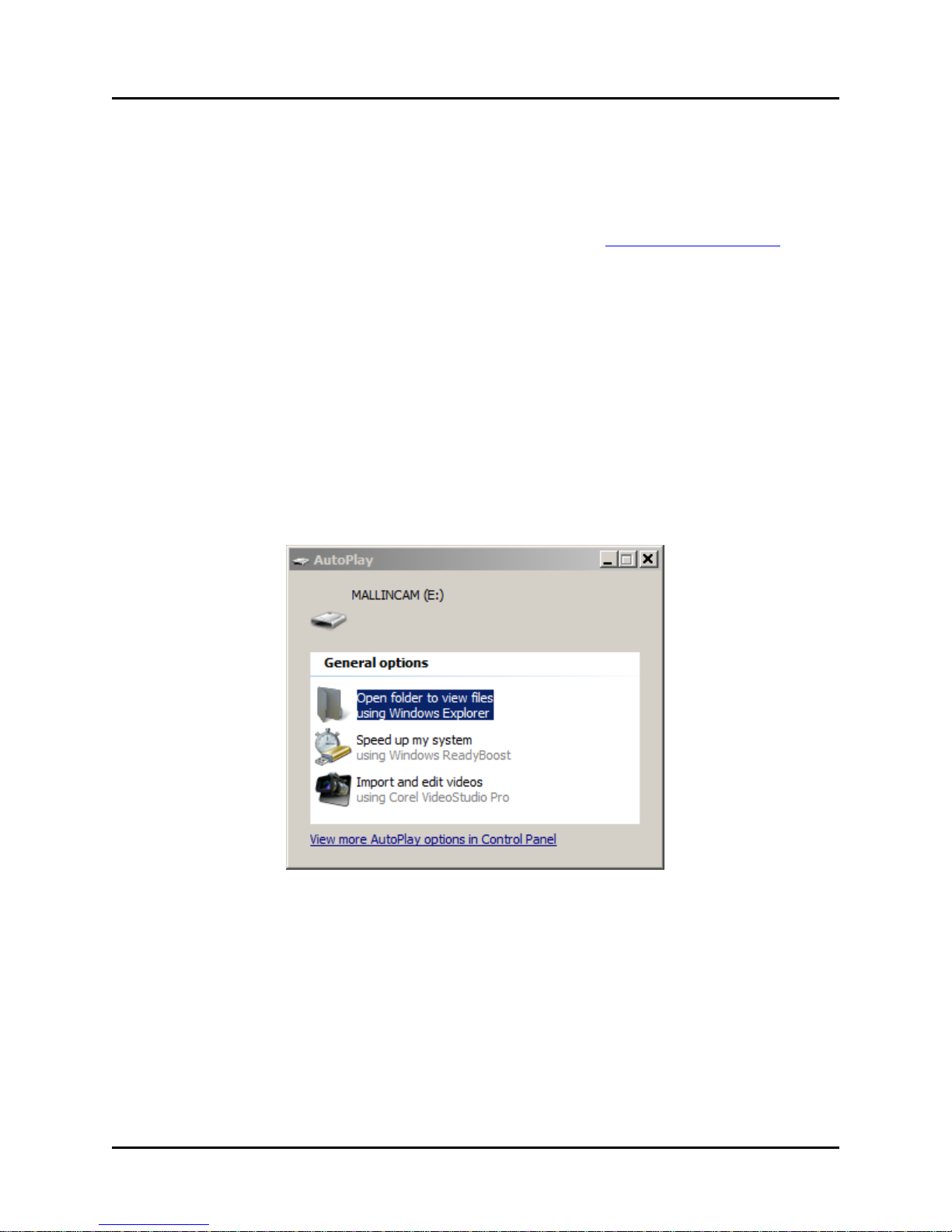
2. Insert the installation disc or flash drive into your computer. A form similar to this is
typically displayed:
3. Click on the Open folder to view files using Windows Explorer option and then click OK.
If this form is not automatically displayed, right-click the My Computer desktop
icon to open Windows Explorer and then click on your CD-DVD drive or flash drive to
view the files.

MallinCam Universe - User’s Guide v1.05 7
4. Double-click the signeddriversetup.exe file. The camera Driver Setup Wizard opens to
install the driver.
5. Click Next to continue. The following message may appear:
If this is displayed, click the Continue Anyway button to install the driver.
6. The Driver Setup Wizard displays a message informing you when the setup has finished
installing the camera driver on your computer.
7. Click Finish to complete the driver installation.
8. In Windows Explorer, double-click the MallinCam Setup.exe file. The MallinCam Setup
Wizard opens:
9. Click Next to start the installation.

MallinCam Universe - User’s Guide v1.05 8
10. The program prompts you for a destination folder to install the files:
You can change the suggested location or click Next to accept the default location.
11. The setup proceeds and notifies you when it is complete:
12. Click Finish to complete the software installation and close the MallinCam Setup
Wizard.
A MallinCam icon is installed on your desktop as part of the procedure. You can use this
later on to launch the application.
13. Remove the disc or flash drive from your computer.
14. Go to Section 4: Hardware Installation to install the hardware.

MallinCam Universe - User’s Guide v1.05 9
Section 4: Hardware installation
After the software has been successfully installed, you must connect the hardware to complete
the initial installation process so that Windows recognizes the camera.
1. Connect the USB 2.0 cable to camera first and then to an available USB 2.0 port on your
computer (USB 1.1 ports are not supported for the MallinCam Universe).
NOTE: You should always attach the USB cable to your camera and computer before
powering up the camera.
2. Check to ensure that the recessed thermo-electric cooler (TEC) switch is in the ON
position. The TEC unit is on when the slider switch is closest to the Power ON indicator.
This is the default position and normally does not need to be changed.
3. Connect the +12 VDC lead from the AC-DC power supply to the camera’s power port.
4. Plug the AC-DC power supply into a power source to turn on the camera. The Power ON
indicator will light. Allow a minute for full stabilization of the hardware.

MallinCam Universe - User’s Guide v1.05 10
5. When the camera is powered up, the Welcome to the Found New Hardware Wizard form
is displayed:
Click the No, not this time radio button and then click Next.
6. On the following form, click on the Install software automatically (Recommended) radio
button and then click Next:
7. The Hardware Installation form may then appear:
If this is displayed, click the Continue Anyway button.
MallinCam Universe - User’s Guide v1.05 11
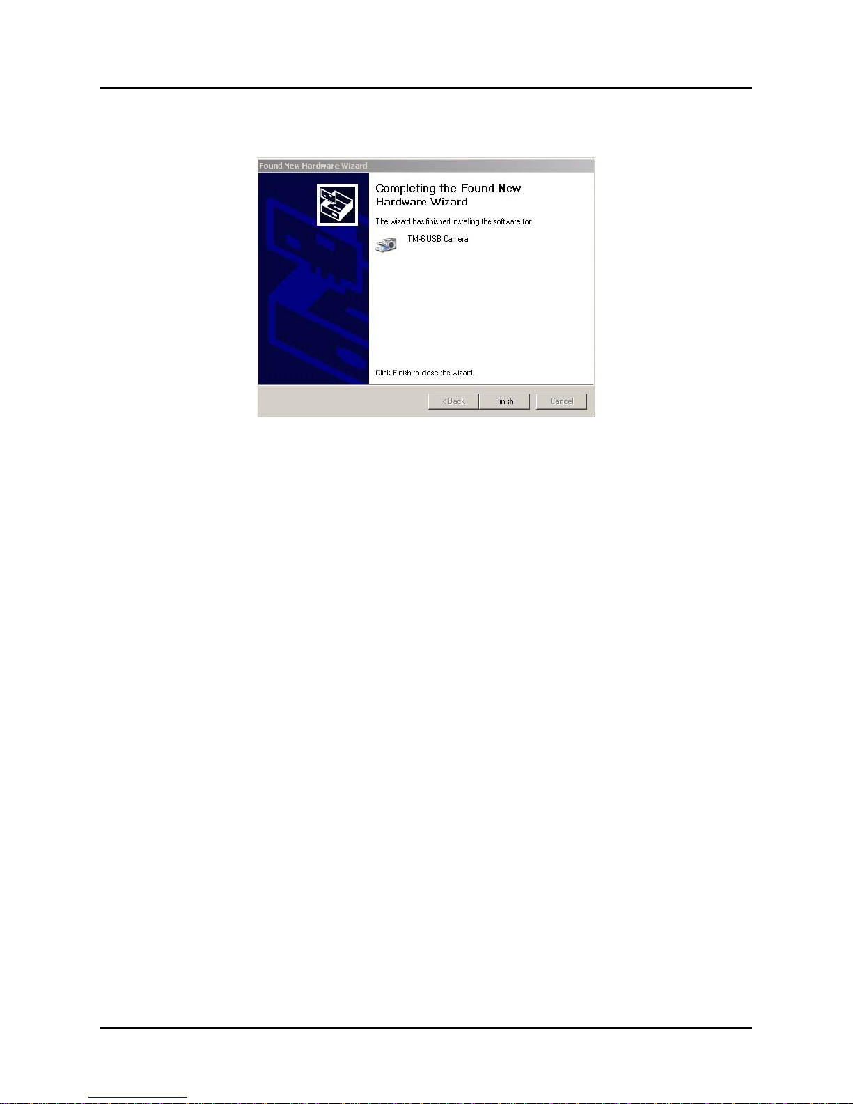
8. The Completing the Found New Hardware Wizard form is displayed when the
installation is done:
9. Click Finish to complete the hardware installation and close the wizard.
Windows then informs you that your new hardware is installed and ready to use.
NOTE: If you plug the Universe camera into a different USB 2.0 port at a later date,
you may have to repeat steps 5 through 7 above. This is typical behavior for some
versions of Windows. If the Welcome to the Found New Hardware Wizard form is not
displayed, then Windows has found the driver automatically and you should be ready to
operate the camera.
You’re now ready to link the camera with the image capture application and start experimenting.
TIP: To familiarize yourself with the installation and operation of the Universe, you may
want to perform the procedures in Section 5, 6and 7indoors prior to your first field session.
Doing so will verify that the system and all its components have been properly installed and
are fully functional. Imaging session time is often all too limited. Test the system and learn
the basics beforehand!
MallinCam Universe - User’s Guide v1.05 12
Section 5: Attaching the camera to your telescope
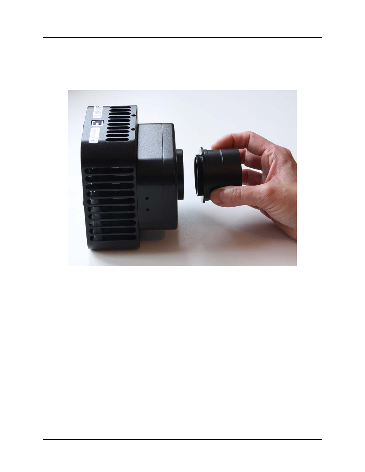
Attaching the MallinCam Universe to the telescope is very straightforward.
1. Unscrew the metal cover protecting the sensor and attach the supplied 2” nosepiece.
NOTE: There are three small set screws in the mounting collar of the camera body.
Make sure these are out far enough to allow the nosepiece to fully seat. After the
nosepiece is installed, you can tighten these down for increased security or permanent
installations. However, the use of these screws is optional.
2. Make sure the nosepiece is firmly attached to the camera and then insert the nosepiece
barrel into your telescope’s focuser.
3. Tighten down the focuser’s attachment locking screws and check that you have a firm fit.
4. Connect the USB 2.0 cable to camera first and then to an available USB 2.0 port on your
computer (USB 1.1 ports are not supported for the MallinCam Universe).
NOTE: You should always attach the USB cable to your camera and computer
before powering up the camera.
5. Check to ensure that the recessed thermo-electric cooler (TEC) switch is in the ON
position. The TEC unit is on when the slider switch is closest to the Power ON indicator.
6. Connect the +12 VDC lead from the AC-DC power supply to the camera’s power port.
7. Plug the AC-DC power supply into a power source to turn on the camera. The Power ON
indicator will light. Allow a minute for full stabilization of the hardware.

MallinCam Universe - User’s Guide v1.05 13
Section 6: Using the MallinCam image capture application
When you launch the MallinCam Universe image capture application, the main MallinCam
window opens. The window contains an image preview panel and displays the Property panel at
the right side. The Picture panel can be displayed by clicking the Picture tab at the bottom-right
corner of the main screen.
The Property panel is used to:
• adjust the various camera settings, including: resolution, exposure time, gain, contrast,
gamma, white balance, and color saturation
• view and adjust a histogram of the current image
• perform an image capture
• set up a sequence of multiple image captures
• set up a sequence of captures to produce a stacked image
The Picture panel is used to:
• manage image formats and files
• preview captured images
• save captured images

MallinCam Universe - User’s Guide v1.05 14
A. Setting up a proper exposure to help achieve focus
Once the camera has been powered up and the MallinCam image capture application opened,
you can start setting up your initial exposure. Before pressing the Start Camera button, you must
set up the resolution for your captured images. You can only adjust this while the camera is
stopped.
In the Control field, use the dropdown menu to select the image resolution. Use the default value
of 3032x2018. This is the camera’s full, unbinned resolution. You don’t have to worry about
setting the 16 Bit control at this point. Either setting will do for the initial setup and focus
adjustments described below.
Click the Start Camera button. The camera begins to capture images and display these in the
preview window. Once the first image is displayed, the camera continues to capture images and
show them sequentially. These are preview images to let you view what the camera sees through
your telescope. They are not saved to your hard drive.
All other controls can now be adjusted while the camera is continually exposing. This “on-the-
fly” capability makes it much easier and quicker to adjust the settings to obtain the image you
want.
The first thing to do is set the exposure length to obtain images that show some level of detail.
If the current exposure time is too short, the image will appear black or very dark. If it is too
long, the image will appear washed out or white.
Procedure 1: Adjusting the exposure length
1. Click the Change Exp button. The Exposure fields become active.
2. Set the desired exposure length in the m-s-ms fields (minutes-seconds-milliseconds) and
click the OK button. This exposure length will be used for both the preview images as
well as any single images you want to capture and save.
3. Keep adjusting this value until you start seeing some details or light variations in the
preview image.
Once you start seeing some light variations, you need to focus your telescope. If your current
focusing adjustment is substantially off, all you may see in the preview images are variations in
brightness levels in different portions of the view. If your focus is not too far off, you will see
round blobs of varying brightness scattered throughout the field. These are out-of-focus stars.
The MallinCam capture application has a feature that greatly simplifies the task of focusing.
Proceed as follows:
Procedure 2: Adjusting the focus using the preview images
1. Set the exposure length for a fairly short interval, somewhere between 500 msec to 3 sec.
This should be adequate for most telescope focal ratios. High focal ratios (F10 and
above) may require longer exposures. Short exposure lengths will give you a quicker
refresh rate on the preview images. This allows for a near real-time approach to focusing,
much like the live view capability of most recent DSLR cameras.
MallinCam Universe - User’s Guide v1.05 15
If you find that the preview is very dark, try increasing the setting of the Gain slider for
now, rather than increasing the exposure length. Set Gain to maximum. This will help to
show brightness variations and defocused stars in the preview. If you’re still having a
problem seeing anything at all in the preview, you can try increasing the exposure length
or even repositioning your telescope so that a bright star is near the center of the field of
view. However in most cases you shouldn’t need to do this.
2. Rack your telescope’s focuser in one direction. If the brightness variations become more
diffuse or the defocused stars become larger and dimmer then you’re going the wrong
way. Rack the focuser in the opposite direction so that the defocused stars become
increasingly smaller and brighter. As you get closer to proper focus, you should begin to
see an increasing number of fainter stars sharpening up in the field.
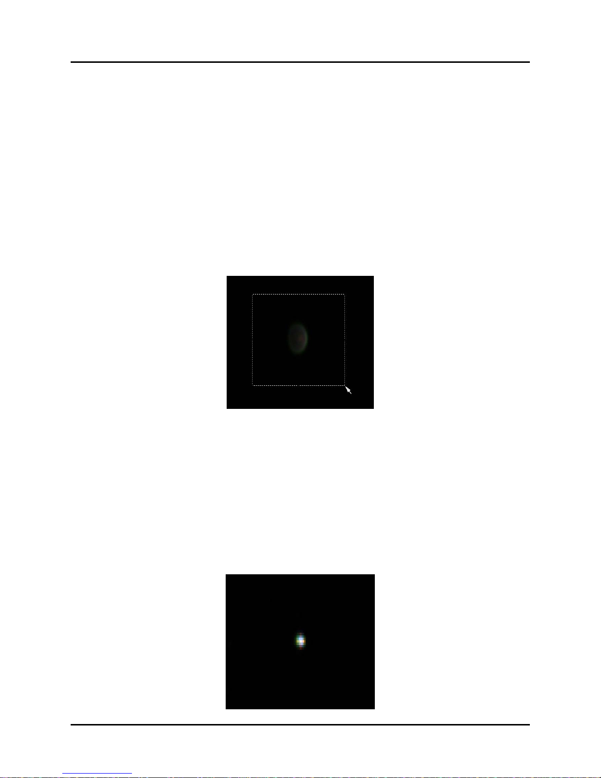
3. When the stars are getting close to focus, place your cursor near a brighter star, click and
hold down the left mouse button and draw a box around the star.
4. Click the Cut Area button in the Area Display portion of the Property panel. The preview
image will then only display the area you selected.
5. Click the Full Screen checkbox in the Area Display. The selected area is enlarged to fill
the screen. You now have a zoomed-in view of the defocused star. This makes seeing
even the tiniest changes in your focusing much easier.
6. If the central portion of the defocused star looks too bright or saturated now, reduce the
Gain and/or the exposure time. You want to see the shape of the star clearly as you focus.
7. Continue adjusting the focus gradually until the star becomes as small and tight as
possible.

MallinCam Universe - User’s Guide v1.05 16
As the star image becomes smaller, it will also become brighter. When you cannot get it
any smaller, you are in proper focus. If it starts to enlarge again, then you’ve gone too far.
Reverse the focusing direction and make very gradual adjustments to tighten it up.
8. When you are satisfied with the focus, click the Restore button in the Area Display. The
preview images will then begin to show the full field again.
TIP: Use the Area Display function once you’re on your target in order to have a closer look
at any portion of a preview image. This can help you to set the exposure controls properly to get
the details you want. Note however that if you do not restore the preview image before taking an
actual capture, then only the selected area will be saved in your captured image file.
At this point, you are ready to adjust the other camera controls to obtain a proper image.
MallinCam Universe - User’s Guide v1.05 17
B. Adjusting the camera controls
All controls used to adjust the appearance of the image are on the Property panel. The camera
must be running and generating preview images to make adjustments. If you click the Stop
Camera button, most of controls become grayed out (inactive). The only adjustments you can
make then are to change the resolution and the bit-depth of the captured images.
Adjustment control usage is detailed in this section. Experiment with the settings to produce the
image you like. There are few hard and fast rules, since astrophotography can be as much art as it
is science. However, by understanding the function of each of the controls and following the
provided suggestions, you’ll be able to use the camera effectively and to its maximum potential.

MallinCam Universe - User’s Guide v1.05 18
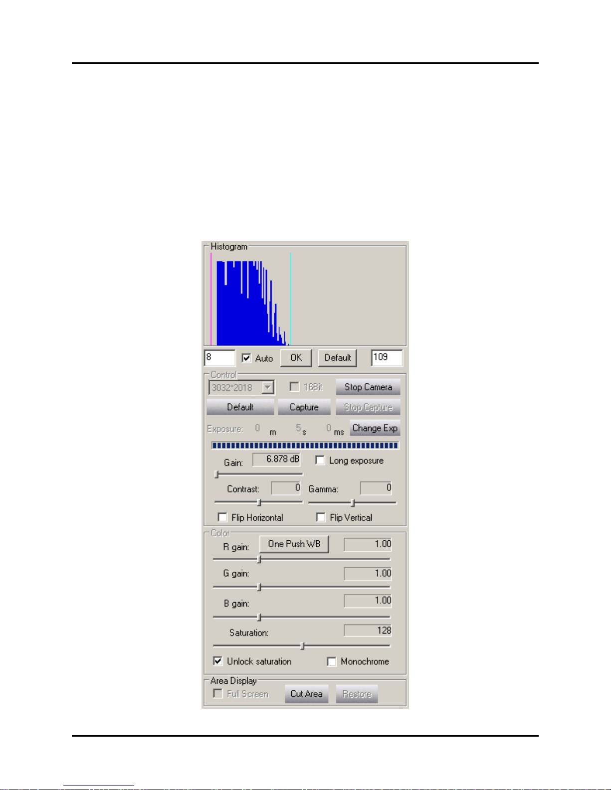
Histogram:
The histogram is a graphical view of the tonal distribution within the image. The horizontal axis
represents the variation in tone, with the darkest pixels to the left (pure black is “0” when the
histogram is not stretched) and the lightest pixels to the right (pure white is “255” in 8-bit mode,
or “4095” in 16-bit mode). The vertical axis and the height of the dark blue column lines
represent the relative number of pixels of a particular tone.
Changing the histogram increases or decreases the visible data in your image. This is called
histogram stretching or dynamic range expansion. Initially, the histogram is set to its Default,
full-range setting (“0” in the left text box below the histogram, and “255” in the right text box).
When you use either the Auto function or the manual method to change the histogram, the values
you set will appear in the text boxes. The minimum value will also be indicated by a vertical red
line on the graph, while the maximum value is indicated by a vertical cyan line. Alter the
histogram by trying one or more of the following methods:
Click the Auto checkbox to let the system determine a histogram stretch. This moves the
minimum and maximum values close to the leftmost and rightmost edges of where the blue
columns first appear in the graph (shown on previous page). The Auto function tries to
maximize the dynamic range displayed onscreen in the preview image, and the image usually
gets noticeably brighter. However, while Auto mode is recommended for use to get an initial
approximation, it is not always the best choice for the final setting of your image.
- OR –
In the manual mode, you can set the minimum and maximum tones to any values in your
image. With the Auto mode unchecked, place your cursor somewhere over the dark blue
histogram columns and right-click the mouse. This sets the maximum and you’ll see a cyan
line appear near where you clicked. Notice how the next preview image changes. Now right-
click again, but this time directly over the rightmost blue column of the graph, which is
where you want it. Repeat as required until you get it as close as possible to the right side.
Similarly, left-clicking inside the dark blue columns of the graph sets the minimum and
you’ll see a red line appear where you clicked. Try to place it directly over the leftmost blue
column of the graph. Repeat as required until you get it as close as possible to the left.
- OR –
For greater precision, use the text boxes below the display to enter your own minimum and
maximum values and then click OK. The Auto checkbox must be unchecked. The range for
each field is 0 to 255 in 8-bit mode (0 to 4095 in 16-bit mode), with the left field to be set
lower than the right. As with the manual mouse-click method, the goal is generally to set the
red line (minimum) over the leftmost blue column of the graph and the cyan line (maximum)
over the rightmost blue column. Keep trying different values until you get these as close as
possible.
Note that you can always click the Default button and then OK to return to the full (unstretched)
histogram range. The Auto checkbox must be unchecked when you do this.
The histogram can also help you to determine if you are exposing your image properly. If you
only have a few blue columns clustered at the left side of the graph, then you are under-exposing.
Similarly, with the majority of the blue columns towards the right, you are over-exposing. Adjust
the exposure length for a greater spread of columns through the middle of the graph, if possible.

MallinCam Universe - User’s Guide v1.05 19
Control:
Used to adjust the image size and effective pixel resolution. You can only set this control while
the camera is stopped.
In the Control field, use the dropdown menu to select the desired image resolution. The default
value of 3032x2018 is displayed initially. This is the camera’s full, unbinned resolution. You can
also choose to bin the exposure by factors of 2x2, 3x3, or 4x4.
Binning combines multiple pixels into fewer, but effectively larger, super-pixels. In 2x2 binning
for example, a square of four adjacent unbinned pixels forms one large super-pixel. This
increases sensitivity, since the binned super-pixel now delivers the combined signal of the four
original unbinned pixels. But the trade off with binning is that since each super-pixel comprises a
larger physical portion of the CCD imaging chip, it “sees” a larger area of the sky, and so the
spatial resolution of each such pixel is decreased. For example, if you select 2x2 Bin, the
captured image size will now be 1516x1008 pixels. It will still show the same total area of the
sky as the unbinned image, but will do so using only half as many pixels in both the vertical and
horizontal dimensions. The actual file size of a saved 2x2 binned image will also be reduced to
about one-quarter that of an unbinned image.
Since binning increases pixel sensitivity, objects such as faint nebulae will generally appear
brighter and more prominent. However, some of the finer details will be lost due to the decreased
spatial resolution.
The image sizes produced by the various binning options are as follows:
• 3032*2018 pixels: images are 3032 x 2018 pixels (full-resolution mode)
• 2x2: images are 1516 x 1008 pixels
• 3x3: images are 1008 x 672 pixels
• 4x4: images are 756 x 504 pixels
Regardless of the binning mode you choose, all images will still be in full color.
16 Bit:
Used to set the bit resolution of captured TIF images. When this option is not selected, TIF files
are saved as 8-bit versions (RGB 24-bit). When the option is selected, the TIF files are saved as
16-bit versions (RGB 48-bit). Although 16-bit is the recommended choice, some image
processing applications cannot read this richer TIF format. Refer to Section 10 for detailed
information on this setting. You can only set this control while the camera is stopped.
Exposure:
Used to adjust the length of an image exposure. You should use this control in conjunction with
adjusting the Contrast and Gamma settings to produce a preview image to your liking.
Click the Change Exp button and enter the desired values in the m-s-ms fields (minutes-
seconds-milliseconds), then click OK.
NOTE: If you have the exposure length currently set for a short interval AND the Auto
histogram function is selected, you may notice that the m-s-ms fields keep resetting to the
previous values as you’re trying to change them. Deselect the Auto histogram function to stop
this behavior. You can re-enable the Auto checkbox after changing the exposure length and
clicking OK.

MallinCam Universe - User’s Guide v1.05 20
Gain:
Used to set the camera’s amplifier sensitivity. You should typically set the gain as low as
possible and adjust the exposure time, contrast, and gamma parameters to produce the image you
want. Set the gain higher if you need the additional boost in sensitivity, for instance, when you
need to keep your exposures as short as possible. This can be beneficial when your telescope
mount’s tracking is not precise, or if you’re imaging an event of short duration.
Select a value between 6.878 dB to 26.007 dB. The higher the value, the more sensitive the
camera will be. However, increasing the value of the Gain will also increase the relative
amount of noise in the image.
Long exposure:
Used to reduce amp glow and hot pixel intensities during long exposures at high gain settings.
If you take a long exposure with the gain set high, you may notice a slight glow in the upper left
corner of the image – that’s amp glow. This results from the CCD chip’s signal amplifier and is
normal. The Universe imager produces very little amp glow and so this is usually not apparent.
However, the amount of amp glow visible will actually depend on the particular combination of
exposure time, gain settings and histogram stretching that you choose:
Shorter exposure times produce less amp glow and fewer, less-intense hot pixels
Lower gain settings produce less amp glow and fewer, less-intense hot pixels
Histogram stretching increases amp glow and hot pixel visibility. If you leave the histogram
at its default (unstretched) setting, the amp glow will be at a minimum. However, this
decreases all the visible data in your image including your target, and so is usually not the
setting you want. Whenever you use the histogram’s Auto function (or set it manually) to get
the best image, you may increase the visibility of amp glow, if it’s there at all.
The Long Exposure control reduces (and in many cases, eliminates) the amount of amp glow
visible. It also reduces the visibility of any hot pixels. You enable this control by clicking in the
checkbox. Note that some of the faintest nebulosity in your image may also be reduced when you
use this setting.
If you want to see the effect of amp glow, try the following. Cap the Universe camera so that no
light reaches the sensor. The images you’ll take here are called dark frames, with the only light
visible coming from the camera itself. Take three 5-minute images with Long Exposure not
selected: one with the gain set to minimum (6.878 dB), the next with gain around the mid-point
(~16 dB), and the last, at maximum (26.007 dB). Now repeat those exposures with Long
Exposure selected. Compare the images to see the effect of altering the gain, with and without
using Long Exposure. Try the same set of images, but this time, make them 10-minute long
exposures. Note the differences between the two sets. Particularly, notice how a 10-minute
exposure at mid-gain actually generates less amp glow than a 5-minute shot at maximum gain.
And again, the overall visible effect will increase on a real target, depending on how much you
stretch the histogram. You’ll get the idea once you do a few of these comparisons.
TIP: You can also reduce or eliminate amp glow in an image by using dark frame subtraction
(refer to Section 10) or by simply cropping your final image in an image processing application.
Other manuals for Universe
2
Table of contents
Other MallinCam Security Camera manuals


