Mamava XL User manual

XL Assembly Instructions
For replacement parts,
questions or concerns, contact:
802.347.2111
Version: XL V5
2/25/2022 Page 1
People required: 2
Average time required: 4 hours

Page 2

Floor Pan (Page 5)
Step 1......
Step 2......
Seats and Counters (Page 6)
Step 3......
Step 4......
Step 5......
Step 6......
Step 7......
Step 8......
Back Wall Panels (Page 7)
Step 9......
Step 10......
Step 11......
Step 12......
Step 13......
Outlet Boxes and Counters (Page 8)
Step 14......
Step 15......
Step 16......
Wiring: Outlet Boxes (Page 9)
Step 17......
Wiring: Outlet Boxes (Page 10)
Step 18......
Wiring: Outlet Boxes (Page 11)
Step 19......
Step 20......
Front Wall Panels (Page 12)
Step 21......
Step 22......
Step 23......
Step 24......
Header and Roof Pans (Page 13)
Step 25......
Step 26......
Step 27......
Step 28......
Step 29......
Wiring: Roof Pan (Page 14)
Step 30......
Wiring: Roof Pan (Page 15)
Step 31......
Wiring: Roof Pan (Page 16)
Step 32......
Wiring: Roof Pan (Page 17)
Step 33......
Wiring: Roof Pan (Page 18)
Step 34......
Beauty Panels (Page 19)
Step 35......
Step 36......
Step 37......
Graphic Panels and Caps (Page 20)
Step 38......
Step 39......
Step 40......
Roof Perf Pans (Page 21)
Step 41......
Step 42......
Door (Page 22)
Step 43......
Step 44......
Table of Contents
(OPTIONAL FRIDGE CABINET)
Fridge Cabinet/Seat and Counters (Page 23)
Step 3......
Step 4......
Step 5......
Step 6......
Step 7......
Step 8......
Wiring: Fridge Cabinet and Outlet Box (Page 24)
Step 18......
Page 3

PARTS LIST
DESCRIPTIONPART NUMBER
FRONT FLOOR PANXL-A101
BACK FLOOR PAN
XL-A103
CHASSISXL-B100
BEAUTY PANELXL-C101
FRONT LEFT WALL PANELXL-D100
FRONT RIGHT WALL
PANEL
XL-D200
BACK LEFT WALL PANELXL-D300
BACK RIGHT WALL PANELXL-D400
BACK MIDDLE WALL
PANEL
XL-D500
DOORXL-D600
BENCHE100
LEFT OUTLET BOX
XL-E200
RIGHT OUTLET BOXXL-E300
LEFT COUNTERXL-E400
RIGHT COUNTERXL-E500
MIDDLE COUNTERXL-E600
MIDDLE WIRE COVER
XL-E607
GRAPHIC CAPXL-F204
MIDDLE ROOF PANXL-F301
SIDE ROOF PANXL-F302
MIDDLE PERF PANXL-F209_M
SIDE PERF PANXL-F209_S
MIDDLE ENHANCED
PRIVACY PANEL
(OPTIONAL)
XL-F210_M
SIDE ENHANCED
PRIVACY PANEL
(OPTIONAL)
XL-F210_S
HEADERXL-H100
GRAPHICS PANELXL-J101
FRIDGE CABINET
(OPTIONAL)
K300
TOOLS REQUIRED
2' Level
6' Ladder
Flat Head Screwdriver
Philips Head #2 Screwdriver
Philips Head #3 Drive Screwdriver
(provided)
Rotolock Allen Key
(provided, 5.5mm)
9/16" Socket Wrench
(for red painted bolts)
**Assembly requires two people**
A101
A103
B100
C101
C101
J101
J101
D500
E300
E200
B100
LOOSE HARDWARE
(8) M8 X 1.25 X 16mm Flat-head Screw
(44) M8 X 1.25 X 25mm Flat-head Screw
(40) M8 X 1.25 X 50mm Flat-head Screw
(16) #8 X 3/4" Pan-head Screw
(8) #6 X 3/4" Wood Screws
(8) Plastic Push Rivets
(12) Rotolock Caps
F302
F204
F204
F209_M
F209_S
F209_S
F209_M
D300
D400
D600
E100
E100
E400
E600
E500
D100
H100
D200
F302
F301
Page 4

FLOOR PAN
1. Set parts on floor as shown.
2. Fasten Front Floor Pan and Back Floor Pan
flanges to Left and Right Chassis.
(8) M8 X 1.25 X 16mm screws
Note: If this is a seismic unit, follow the instructions included
in the seismic kit before continuing to step 1 of this document.
CHASSIS
B100
BACK FLOOR PAN
A103
FRONT FLOOR PAN
A101
CHASSIS
B100
Page 5
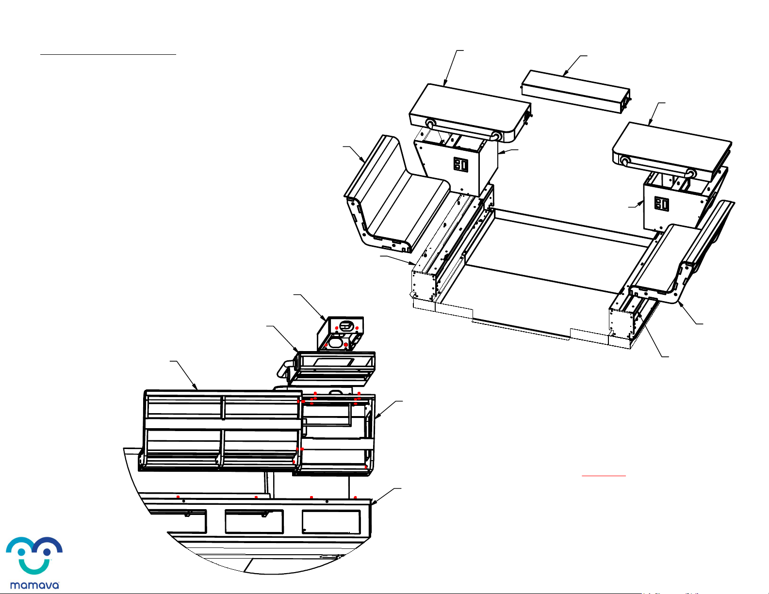
3. Fasten bottom of Left Outlet Box to top of Left Chassis,
and bottom of Right Outlet Box to top of Right Chassis.
(2 per side) M8 X 1.25 X 25mm screws
4. Fasten bottom of Left Counter to top of Left Outlet Box,
and bottom of Right Counter to top of Right Outlet Box.
(4 per side) M8 X 1.25 X 50mm screws
5. Fasten ends of Middle Counter to Left and Right Counters.
(2 per side) M8 X 1.25 X 50mm screws
6. Fasten bottom of Seat to top of Chassis, both sides.
(2 per side) M8 X 1.25 X 25mm screws
7. Fasten end of Seat to Outlet Box, both sides.
(3 per side) M8 X 1.25 X 50mm screws
SEATS AND COUNTERS
Note: See Page 23 if this unit
came with the optional Fridge Cabinet.
8. Level base in both directions with 9/16" socket wrench
and 2' Level (red painted bolts on Chassis).
MIDDLE COUNTER
E600
SEAT
E100
SEAT
E100
CHASSIS
B100
CHASSIS
B100
SEAT
E100
RIGHT COUNTER
E500
MIDDLE COUNTER
E600
RIGHT OUTLET BOX
E300
CHASSIS
B100
LEFT COUNTER
E400
RIGHT COUNTER
E500
LEFT OUTLET BOX
E200
RIGHT OUTLET BOX
E300
Page 6

BACK WALL PANELS
9. Hook Back Middle Wall Panel onto
back of Middle Counter.
10. Hook Back Left Wall Panel onto top
of Left Chassis.
11. Hook Back Right Wall Panel onto top
of Right Chassis.
12. Ensure wall panels are tight together
and flush at top.
Rotolock back panels together with
provided allen key.
13. Place Rotolock caps over holes.
ROTOLOCK
HOLES
BACK LEFT WALL PANEL
D300
BACK MIDDLE WALL PANEL
D500
BACK RIGHT WALL PANEL
D400
RIGHT COUNTER
E500
MIDDLE COUNTER
E600
LEFT COUNTER
E400
CAUTION! Rotolocks are not designed to
pull panels together, doing so may
damage them!
Page 7

OUTLET BOXES AND COUNTERS
14.Fasten Middle Counter to Back Middle Wall Panel.
(2) M8 X 1.25 X 50mm screws
15. Fasten Chassis to Back Wall Panel, both sides.
(4 per side) M8 X 1.25 X 25mm screws
16. Fasten Outlet Box to Back Wall Panel, both sides.
(6 per side) M8 X 1.25 X 50mm screws
MIDDLE COUNTER
E600
CHASSIS
B100
CHASSIS
B100 LEFT OUTLET BOX
E200
RIGHT OUTLET BOX
E300
MIDDLE COUNTER
E600
BACK LEFT WALL PANEL
D300
BACK MIDDLE WALL PANEL
D500
BACK RIGHT WALL PANEL
D400
Page 8

17. Feed GFCI Wire through Middle Counter
and Left counter holes. Connect to Left J-Box.
WIRING: OUTLET BOXES
GFCI WIRE
GFCI WIRE
MIDDLE COUNTER
E600
LEFT COUNTER
E400
LEFT J-BOX
Page 9
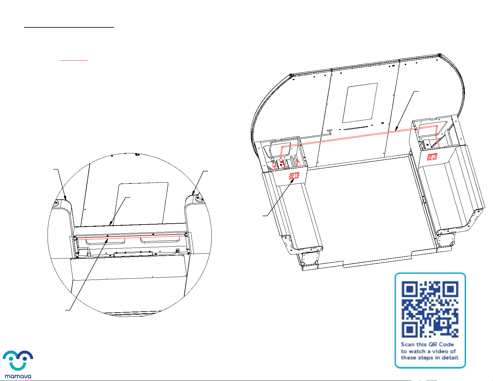
18. Feed Right J-Box Wire out through Right Counter,
Middle Counter, and Left counter. Connect to Left J-Box.
WIRING: OUTLET BOXES
Note: See Page 24 if this unit
came with the optional Fridge Cabinet.
RIGHT J-BOX
WIRE
RIGHT J-BOX WIRE
MIDDLE COUNTER
E600
LEFT COUNTER
E400 RIGHT COUNTER
E500
LEFT J-BOX
Page 10

19. Feed PCD power cord through
Middle Counter and Left Counter. Connect to Left J-Box.
20. Screw Middle Wire Cover into bottom of Middle Counter
and plug GFCI Wire coming out of back of unit into wall outlet.
(8) #6 X 3/4" wood screws
WIRING: OUTLET BOXES
PCD POWER CORD
PCD POWER CORD
MIDDLE COUNTER
E600
LEFT COUNTER
E400
MIDDLE WIRE COVER
E607
LEFT J-BOX
Page 11

FRONT WALL PANELS
21. Hook Front Left Wall Panel
onto top of Left Chassis.
22. Hook Front Right Wall Panel
onto top of Right Chassis.
23. Fasten Chassis to Front Wall Panel, both sides.
(4 per side) M8 X 1.25 X 25mm screws
24. Fasten Seat to Front Wall Panel, both sides.
(3 per side) M8 X 1.25 X 50mm screws
FRONT LEFT WALL PANEL
D100
FRONT RIGHT WALL PANEL
D200
Page 12
DETAIL E
E
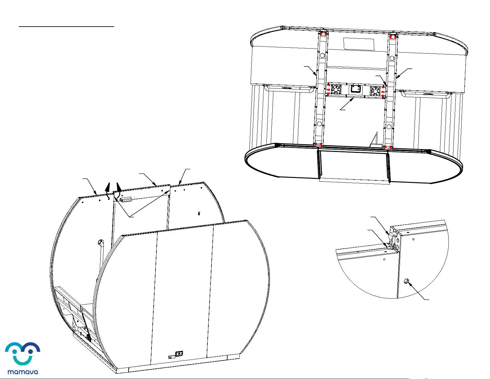
HEADER AND ROOF PANS
25. Pop Header Brackets into Wall Panel Bracket Slots by
pushing downard on Header. Rotolock Header to Front Left
Wall Panel and Front Right Wall Panel with provided allen key.
26. Drop Side Roof Pan into slot on top of
Wall Panels as shown, both sides. Side Roof
Pan with red dots goes on the right. Match up
red dots on Middle and Side Roof Pan.
27. Fasten Side Roof Pan to Wall Panels,
both sides.
(4 per side) M8 X 1.25 X 25mm screws
28. Drop Middle Roof Pan in between Side Roof Pans,
align tabs on Middle Roof Pan with slots in Side Roof Pans.
29. Fasten Middle Roof Pan to Side Roof Pans.
(6) M8 X 1.25 X 25mm screws
ROTOLOCK
HOLES (2)
FRONT RIGHT WALL PANEL
D200
FRONT LEFT WALL PANEL
D100
HEADER
H100
HEADER BRACKET
BRACKET SLOT
ROTOLOCK HOLE
SIDE ROOF PAN
F302 SIDE ROOF PAN
F302
MIDDLE ROOF PAN
F301
RED DOTS
Page 13

WIRING: ROOF PAN
30. Connect Middle Wire Harness to
the DeadBolt Harness and Lockset Harness.
DEADBOLT
HARNESS LOCKSET HARNESS
MIDDLE
WIRE HARNESS
DEADBOLT
HARNESS
MIDDLE
WIRE HARNESS
LOCKSET
HARNESS
Page 14

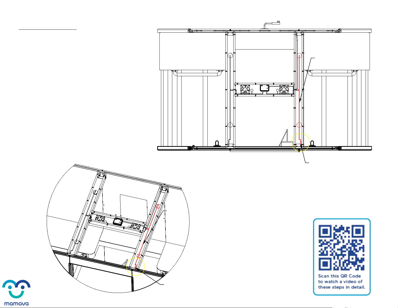
WIRING: ROOF PAN
31. Connect Deadbolt Harness to
Front Left Wall Panel Wire.
DEADBOLT
HARNESS
FRONT LEFT WALL
PANEL WIRE
DEADBOLT
HARNESS
FRONT LEFT WALL
PANEL WIRE
Page 15
WIRING: ROOF PAN
32. Connect Lockset Harness to
Front Right Wall Panel Wire.
LOCKSET HARNESS
FRONT RIGHT
WALL PANEL WIRE
LOCKSET
HARNESS
FRONT RIGHT
WALL PANEL WIRE
Page 16
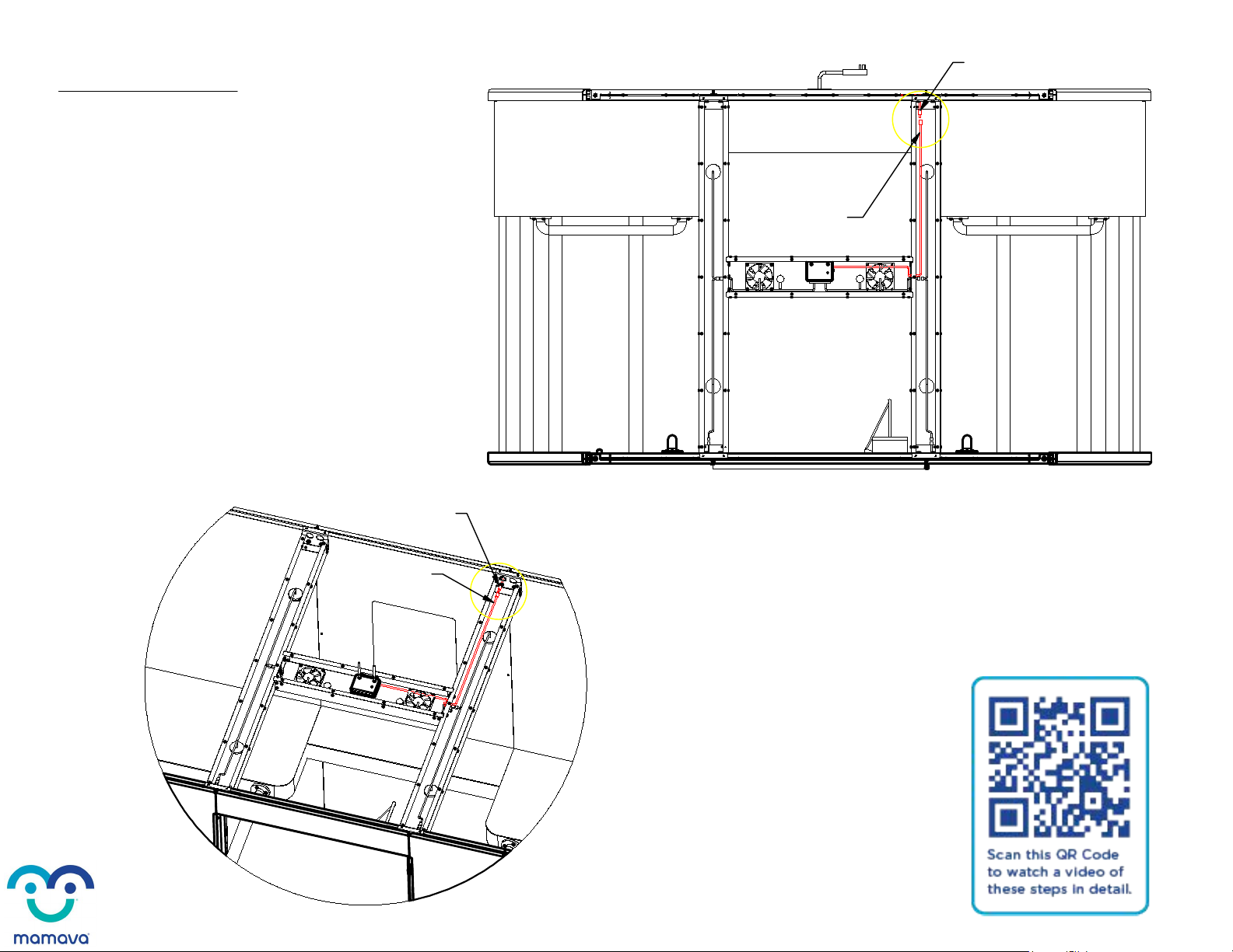
WIRING: ROOF PAN
33. Plug Power Cord Extension into the
PCD Power Cord and flip up PCD antennas.
POWER CORD
EXTENSION
PCD POWER CORD
POWER CORD
EXTENSION
PCD POWER CORD
Page 17

WIRING: ROOF PAN
34. Hold down the plunger switch located in the
deadbolt hole on the Latch Side Wall Panel.
Verify that both lights and fans turn on when the
switch is depressed.
FANS
LIGHTS
FRONT LEFT WALL PANEL
D100
DEADBOLT
HOLE
Page 18

DETAIL F
F
BEAUTY PANELS
36. Slide Left Beauty Panel under Left Seat,
lock Rotolock with allen key in two places.
Add rotolock caps to holes.
(2 caps)
37. Slide Right Beauty Panel under Right Seat,
lock Rotolock with allen key in two places.
Add Rotolock caps to holes.
(2 caps)
35. **If unit needs to be moved, raise
leveling feet located in bottom corners
of the Chassis (red painted bolts).
Once unit is in the right spot,
level it in both directions with
9/16" socket wrench and 2' Level**
ROTOLOCK HOLES
(2)
BEAUTY PANEL
F102
BEAUTY PANEL
F102
HOOK BOTTOM FLANGE ONTO
CHASSIS BEFORE SLIDING
TOP FLANGE UNDER SEAT
TOP FLANGE
CHASSIS
B100
Page 19

38. Place ladder inside unit. Feed Graphic
Panel overhead and into slots in the
Wall Panel Channels, both sides.
39. Fasten Graphic Cap to Front and Back
Wall Panels, both sides.
(2 per side) M8 X 1.25 X 25mm screws
(4 per side) #8 X 3/4" Pan-head screws
40. Fasten Side Roof Pan to top of
Front and Back Wall Panels, both sides.
(4 per side) #8 X 3/4" Pan-head screws
GRAPHIC PANELS AND CAPS
GRAPHIC PANEL
J101
WALL PANEL
CHANNEL
SIDE ROOF PAN
F302
SIDE ROOF PAN
F302
GRAPHIC CAP
F204
GRAPHIC CAP
F204
WALL PANEL
CHANNEL
NOTE: Be sure to orient the Graphics Panel
so the side marked 'INTERIOR' faces inside
the pod when installed.
Page 20
Other manuals for XL
1
Table of contents
Other Mamava Medical Equipment manuals


Popular Medical Equipment manuals by other brands

Boston Scientific
Boston Scientific EASYTRAK 2 IS-1 Physician's lead manual

Basic American
Basic American Zenith 7000 Instructions for use and service manual

Planmeca
Planmeca ProOne user manual

Acon
Acon Mission Ultra manual

Spacelabs Healthcare
Spacelabs Healthcare Pathfinder SL Operation manual

Storz
Storz ENDOMAT SELECT UP 210 Instructions for use


