Mamoli MV35 HUNTER User manual

Designer: Luigi Volonte
MV35 HUNTER - plan 1
18b
a

Designer: Luigi Volonte
MV35 HUNTER - plan 1

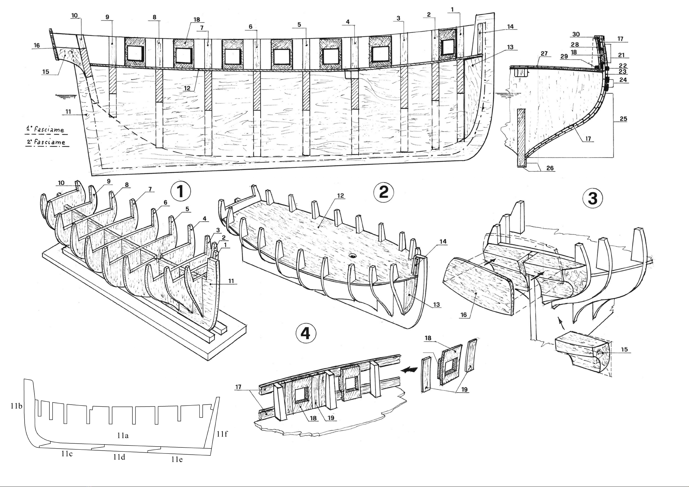
1) Fissare su una tavoletta di legno ben piana, di circa 15 mm. di spessoref 2 listeili o strisce di compensate) spesse 4 mm,, distanti
tra loro 4 mm., in rnodo che vi si pos&a in-castrare la chiglia e che questa vi rimanga in posizione rettilinea e verlicale. Monlare, $enza
incollare. !e ordinate 1...10nei rispettivi incastri sulla chiglia 11, assicurarsi che le ordinate risultino a filo della linea superiore della
chiglia. Controllare 1‘alllnea-mento della struttura; osserv/andola frontaimente, le linee superior! delle ordina'e devo-no presentarsi
su diversi piani ma esattamente parallele tra loro. Eventual! piccole cor-rezioni possono venire apportate ritoccando gli incastri.
Smontare completamente e rico minciare il montaggio incollando le ordinate secondo I'ordine numerico, controllare anco ra
I'allineamento e correggere gli eventual! difetti tendendo degli elastic) agganciati tra le estremita delle ordinate e qualche chiodino
piantato su! fianco della tavoletta di base.
In linea di massima, se il premontaggio e stato eseguito con cura, quest'ultima operazione non e necessaria. Tra un'operazione di
montaggio e la successiva, 6 bene lasciare un in-tervallo di almeno un'ora affinche la colla abbia il tempo di solidificarsi. Durante
questo tempo controllare ancora, guardando la struttura dall'alto, che le ordinate formino un an golo retto con la chiglia (fig. l).
2) Incastrare a fondo sulla struttura la coperta 12 e incollarla, fermandola con chiodini piantati provvisoriamente solo a meta (per
poterli in seguito asportare) in corrisponden-za della chiglia e delle ordinate, vicino agli incastri. Incollare a prua, ai lati della chiglia,
le false ordinate 13 a contatto dell'ordinata 1 e della coperta; sopra questa incollare j pezzetti di listello 14 (fig. 2). Incollare ! blocchetti
di poppa 15 a fllo del piano supe riore dell'ordinata e aggiustarli seguendo il profilo dei fianchi della stessa; incollare lo specchio di
poppa 16 (fig. 3).
3) Preparare la struttura a ricevere il primo fasciame aggiustando le ordinate di prua e I relativi appoggi 13, asportando io spigolo
anteriore delle ordinate, senza toceare II prof[ lo originale corrispondente alio spigolo posteriore. Ripetere lo stesso lavoro sulle
ordinate di poppa: in questo caso e lo spigolo posteriore che va aggiustato. Controllare il cor retto andamento delle linee del fasciame
appoggiando un listello sulle ordinate in diverse posizioni. II fasciame e costituito da 2 strati di Ustelll, il primo di legno tenero, il
secon do formato da listeili piu stretti e so111 Is di bosso e noce. Prima di essere messi in opera i listeili vanno lasciati a bagno per
circa mezz'ora al fine di renderli flessibili. Essi ven gono poi montati alternativamente sui fianchi dello scafo, cost da non provocare
deforma-zioni della struttura dovute alia tensione dei listeili. Oltre che sulle ordinate, i listeili vanno incollati anche tra loro e fermati
con chiodini piantati a meta, per poterli togliere a fasciatura ultimata. Prima di incollare un listello controllare, appoggiandolo sulle
ord[ nate, che I'andamento sia regolare: pu6 accadere che qualche ordinata "manchi'1 o sia ab-bondante; in tal caso correggere
Inserendo tra il listello e I'ordinata dei pezzetti di listed lo sottile, oppure limare I'ordinata. incollare il primo listello 17 col lato
inferiore a filo del bordo superiore della coperta; appoggiare sul listello, senza incollare, un sabordo 18 e con questo segnare sulle
ordinate la posizione dove incollare il secondo listello . Incollare i sabordi incastrati tra i due listeili curando che rimangano in
posizione veriicale. Riempire coi listeili 19 lo spazio vuoto rimasto tra i sabordi e le. ordinate (fig. 4). Comple tare if primo fasciame
proseguendo la posa dei listeili verso Malto e verso il basso fine alia chiglia, terminando secondo la linea tratteggiata indicata sulla
vista in sezione. Per un corretto rivestimento e necessario rastremare i listeili verso prua (fig. 5); rivestire la parte, inferiore dello
specchio di poppa coi listeili 20 (fig. 6). Aggiustare con una lima per legno e carta vetrata a grana grossa tutta la superficie del fasciame
compreso la par te sporgente di piombo dei sabordi.
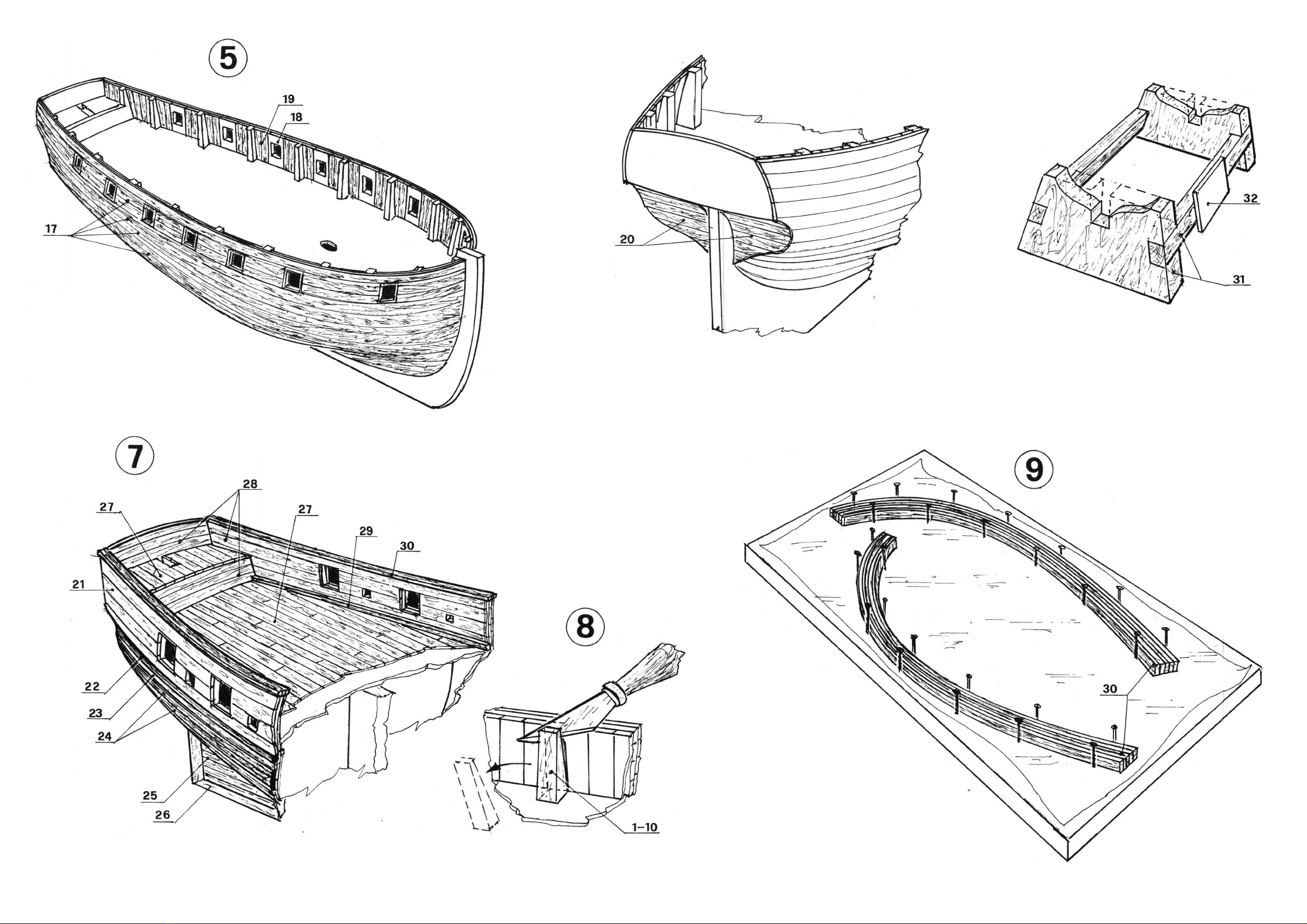
4) Montare il secondo fasciame incominciando dalla fascia di listeili 21, poi Incollare I'in cintone 22, il listello 23, I'inclntone 24 e
completare col fasciame 26 il quale, verso il basso, terinina di piatlo sulla chiglia come indicato dalla linea tralto e punto sulla vista in
sezione. Rivestire la parte scoperta della chiglia coi listeili 26 (fig. 7). Asportare la parte del le or dinate sporgente sopra la coperta
(fig. 8), rivestire la coperta e il casse-ro col lavolato 27 e le pareti interne delle murate coi listeili 28; incollare il trincarino 29 (fig. 6).
Duta la forte curvature, il corrimano 30 e formato a parte incollando tra loro 5 listeili da 1x2; appoggiare su un piano il disegno con
la vista in pianta, proteggere con un foglio di plastica e appoggiarvi i listeili incollati, tenuti in posizione con chiodini. A colla asciutta,
togliere il corrimano, aggiustare e incollarto sul bordo dello scafo (fig. 9). Dipingere di rosso I'interno dei sabordi, forare da 3 mm. la
murala e squadrare i fori con una lima quadra (fig. 7 e tav. A). Montare il supporto 31, adattare la pairte superiore alio scafo e incollare
la targhetta 32 (fig. 10).
1) Fix 2 laths or plywood strips, 4 mm. thick, having a distance of 4 mm. from each other on a flat wooden board, about 15 mm. thick.
In this way the keel can be fitted between the 2 strips in a vertical and straight position. Fit the frames 1... 10 into the respective
grooves on the keel 11, without glueing them, take care that the frames are at the edge of the upper line of the keel. Check the
alignment of the structure; facing it, the upper lines of the frames must be on different planes, but exactly parallel to each other.
Possible small corrections can be made retouching the grooves. Dismount completely, then restart the assembly and glue the frames
following the numerical order, check again the align -merit and correct the possible defects stretching some rubber bands hooked
bjetween the end of the frames and some nails driven into the side of the base board. As a general rule if the pre-assembly has been
accurately done, the last operation is unnecessary. Between two subsequent operations it is advisable to leave an hour's interval, so
as to let the glue dry. Meanwhile check again the frames; looking down on the structure, they must form a right angle with the keel
(fig. 1).
2) Set firmly the deck 12 on the structure and glue it, fix it with little nails driven in only for half of their length (so as to take them out
afterwards) near the joints on the keel and the frames. Glue at prow, at the keel sides, the dummy frames 13 in touch with the frame
1 and the deck; glue on the deck the pieces of strip 14 (fig. 2). Glue the stern blocks at the edge of the upper surface of the frame and
adjust them following the profile of the frame sides; glue the transom 16 (fig. 3).
3) Prepare the structure for the application of the first planking adjusting the prow frames and the relative supports 13, cut away the
fore edge of the frames, without touching the original profile corresponding to the back edge. Repeat the same operation with the
stern frames, in this case it is the back edge which must be adjusted. Check that the lines of the planking are regular, laying a strip on
the frames, in different positions The plan-king consists in two layers of strips, the first of soft wood, the second make of narrower and
thinner strips in boxwood and walnut. Before applying the strips, they must be put in soak about half an hour, so as to make them
flexible. They must then be applied alternatively on one side and on the other of the hull, so as to avoid any deformation of the
structure, caused by the tension of the strips. The strips must be glued on the frames and to each other and must be fixed in position
with nails; they are only partly driven in so as to be taken out when the sheathing is over. Before glueing a strip, take care of its regular
line, laying it on the frames; it may happen that some frames are too narrow or too large; in such case insert between the strip and
the frame some pieces of thin strip or file the frame. Glue the first strip 17 with the lower side at the edge of the upper edge of the
deck; lay a gun-port 18 on the strip, without glueing it, and mark on the frames the position where the second strip must be glued.
Glue the gun-ports between the 2 strips taking care of their vertical position. Fill the empty space between the gun-ports and the
frames with the strips 19 (fig. 4). Complete the first planking, carrying on the application of the strips upwards and downwards as far
as the keel and end as indicated by the dashed line on the sectional view. To obtain a correct sheathing it is necessary to taper the
strips toward the prow (fig. 5); sheathe the lower part of the transom, with the strips 20 (fig. 6). Adjust with a file and rough-grained
sandpaper the whole surface of the plan king between the protruding part of the gun-ports in lead.
4) Apply the second planking starting from the band of strips 21, then glue the sheerstrake 22, the strip 23, the sheerstrake 24 and end
with the planking 26, which, In the lower part, ends flat on the keel as indicated by the dot-and-dash line on the sectional view. Sheathe
the uncovered part of the keel with the strips 26 (fig* 7). Cut the part of the frames sticking out above the deck (fig. 8), sheathe the
deck and the quarter-deck with the planking 27 and the inside walls of the bulwarks with the strips 28; glue the stringer 29 (fig. 6). In
consideration of the strong bending, the handrail 30 is prepared separately glueing 5 strips 1x2; lay on a surface the drawing with the
top view, protect it with a plastic sheet and lay on it the glued strips, kept in position with little nails. When the glue Is dry, remove the
handrail, adjust and glue It on the edge of the hull (fig. 9). Paint red the inside of the gun-ports, bore the bulwark (3 mm.) and square
the holes with a square file (fig. 7 and table A). Assemble the stand 31, fit the upper part on the hull and glue the plate 32 (fig. 10).
1) Fixer sur une tablette de bois bien plane, d'environ 15 mm. d'épaisseur, 2 lattes, ou bandes de contreplaqué, de 4 mm. d'épaisseur, à une distance de 4 mm. l'une de l'autre, f de façon a pouvoir encastrer la quille en
position rectiligne et verticale. Monter, sans coller, les couples 1... 10 dans les entailles respectives sur la quille 11, s'assurer que les couples résultent au fil de la ligne supérieure de la quille. Contrôler l'alignement de toute
la structure: l'observant de front, les lignes supérieures des couples doivent se présenter sur des plans différents, mais exactement parallèles entre elles. D'éventuelles petites corrections pourront être effectuées retouchant
les entailles. Démonter complètement et recommencer le montage collant les couples, suivant l'ordre numérique. Contrôler encore l'alignement et corriger les défauts éventuels tendant des élastique accrochés entre les
extrémités des couples et quelques clous plantés sur le flanc de la tablette de base. En principe, si le prémontage a été exécuté avec soin, cette opération n'est pas nécessaire. Entre une opération de montage et la suivante
il faut laisser un Interval «d'une heure au moins afin que la colle ait le temps de se solidifier. Entretemps contrôler q\je, regardant la structure d'en haut, les couples forment un angle droit avec la quille (fig. 1).
2) Encastrer à fond sur la structure le pont supérieur 12 et le coller, le fixer en pcfSltton avec de petits clous plantés seulement à moitié (pour pouvoir ensuite les enlever) en correspondance de la quille et des couples, près
des emboîtements* Coller à proue, aux cô-Ijés de la quille, les fausses charnières !3 en contact du couple ! et du pont supérieur; coller sur le pont les pièces de latte Î4 (fig. 2). Coller les blocs de poupe 15 au fil du plan
supérieur du couple et les ajuster suivant le profil des flancs; coller le miroir de poupe 16 (fig. 3).
3) Préparer ia structure à recevoir le premier bordé, ajustant les couples de proue et les appuis relatifs 13; enlever l'arête antérieure des couples, sans toucher le profil orl ginal correspondant à l'arête postérieure* Répéter
la même opération sur les couples de poupe; en ce cas il faut ajuster l'arête postérieure«, Contrôler que les lignes du bordé soient correctes appuyant une latte sur les couples en différentes positions. Le bordé est formé
de 2 couches de lattes, la première de bois tendre, la seconde formée de lattes plus étroites et subtiles de buis et de noyer. Avant d'être appliquées, les lattes devront être laissées à bain pendant une demi-heure afin de
les rendre flexibles. Elles sont ensuite montées alternativement sur un flanc et l'autre de la coque, de façon à ne provoquer aucune déformation de la structure due à la tension des lattes. Outre que sur les couples, les
lattes doivent être collées entre elles et fixées avec de petits clous plantés à moitié, pour être enlevés lorsque Se bordé sera achevé. Avant de coller une latte, contrôler, l'appuyant sur les couples, que la ligne soit régulière;
il peut arriver que quelques couples "manquent1* ou solent trop abondants; en ce cas corriger insérant des pièces de latte subtile entre la latte et le couple, ou bien limer le couple. Coller la première latte 17 avec le côté
inférieur au fil du bordé supérieur du pont; appuyer sur la latte, sans co_l_ 1er, un sabord 18 et marquer sur les couples la position où la deuxième latte doit être co_[ lée. Coller les sabords encastrés entre les deux lattes
de façon qu'elles restent en position verticale. Remplir avec les lattes 19 l'espace vide entre les sabords et les couples (fig. 4). Compléter le premier bordé collant les lattes vers le haut et vers le bas jusqu'à la quille, achever
selon la ligne hachurée indiquée sur la vue en section. Pour obtenir un doublage correct il est nécessaire de réduire la largeur des lattes vers la proue (fig. 5), doubler la partie inférieur du miroir de poupe avec les lattes 20
(fig. 6). Ajuster avec une lime pour bois et du papier de verre à gros grains toute la surface du bordé entre la partie saillante en plomb des sabords.-
4) Monter le second bordé à partir de la bande de lattes 21, ensuite coller la préceinte 22, la latte 23, la préceinte 24 et compléter le bordé 26 qui, vers le bas, finit à plat sur la quille comme indiqué par la ligne trait et point
sur la vue en section. Doubler la partie découverte de la quille avec les lattes 26 (fig. 7). Enlever la partie des couples saillante au-dessus du pont (fig. 8), doubler le pont et le gaillard d'arrière avec le bordé 27 et les parois
intérieures des murailles, avec les lattes 28; coller la partie 29 (fig. 6). En consj dération de la forte courbure, la main courante 30 est formée à part collant entre elles 5 lattes 1x2; appuyer sur une surface le dessin avec le
plan, protéger avec une feuille de plastique et appuyer les lattes collées, tenues en position avec de petits clous. Lorsque la colle est sèche, enlever la main courante, ajuster et la coller sur le bord de la coque (fig. 9). Peindre
en rouge l'intérieur des sabords, percer (3 mm.) la muraille et équarrir les trous avec une lime carrée (fig. 7 et table A). Monter le support 31, adapter la partie supérieure à la coque et coller la plaquette 32 (fig. 10).
1.) Auf eine glatte Hoiztafel, 15 rnm. Dicke, 2 Leisten 4 mm. (4 mm. voneinander entfernt) befestigen, so dass man den Kiel in die richtige, senkrechte Stellung einschieben kann. Ohne einzukleben, die Spanten 1... 10 In
die bestimmten Einschnitte auf den Kiel 11 eins et zen; gut kontrollieren, dass die Spanten gut an der Oberlinie des Kiels stehen. Die Einreihung der Struktur gut und genau kontrollieren: vorderseitig müssen die OberIinien
der Spanten auf verschiedene Flächen, aber untereinander genau parallel, sein. Durch kleine Änderungen der Fugen, kann man auch eventuelle Verbesserungen bekommen. Alles ausbauen, den Bau vom Anfang
Wiederbeginnen, die Spanten nach der Nummerreihe einkleben, nochmals die Einreihung kontrollieren und eventuelle Fehler, mit der Hilfe von Gummibün dern auf den Spantenenden und einigen Nägelchen auf der
Seite der Grundtafel, verbes -sern. Diese letzte Arbeit ist aber normaler weise nicht so dringend, wenn der Vorbau Ist genau und sorgfältig gemacht worden. Unter allen Einbauarbeiten ist es gut eine Pause von einer
Stunde eingeführ zu haben, so dass der Lelm trocken werden kann. Inzwischen nochmals gut kontrollieren, dass die Spanten einen rechten Winkel mit dem Kiel bestimmen (man muss die Struktur von oben beobachten)
(Bild l).
2) Das Deck 12 gut auf die Struktur einsetzen, sie einkleben und sie mit provisorisch geschlagenen Nägelchen (beim Kiel und den Spanten) neben die Fugen fixieren. Man muss die Nägelchen später herausziehen. Am
Vorschiff, an den Seiten des Kiels, die falschen Span ten 13 auf das Spant 1 und auf das Deck einkleben; darauf, die Leistenstücke 14 einkleben (Bild 2). Die Heckblöcke 15 an die Ober fläche des Spanten einkleben, sie
nach dem Profil
3) Die Struktur für die erste Beplankung bereiten, die Vorschiffsspanten und die betreffenden Stützen 13 ausgleichen, die Vorderecke der Spanten abnehmen, ohne das Originid profil an der Hinterecke zu verändern.
Dieselbe Arbeit auf die Heckspanten machen, aber diesmal in Verhältnis zur Hinterecke. Mit einer Leiste auf den Spanten, in verschie denen Stellungen, dein korrekten Lauf der Linien der Beplankung kontrollieren. Die
Beplankung besteht aus 2 Leistenschichten, der ersten aus süssem Holz, der zweiten aus dünneren und kleineren Buchs- und Nussholzleisten. Bevor man sie einsetzt, muss man sie eine halbe Stunde im Wasser liegen
lassen, so dass sie biegsamer werden. Sie werden später abwechselnd auf die Seiten des Schiffsrumpfes eingesetzt, so dass man keine Verformungen der Struktur verursacht. Man muss die Leisten auch untereinander
kleben und sie mit nur halb eingeschlagenen Nägelchen fixieren, so dass man sie später herausziehen kann. Bevor man eine Leiste einklebt, muss man kontroll ieren, dass der Lauf regelmässig ist: es kann sein, dass einige
Spanten "fehlen" oder zu breit sind: in diesem Fall, alles verbessern (durch Leistenstücke zwischen die Leiste und das Spant), oder das Spant feilen. Die erste Leiste 17 mit der Unterseite an den Oberrand des Decks
einkleben; auf die Leiste, ohne einzukleben, die Pforte 18 anlehnen und, auf die Spanten, die richtige Stellung der zweiten Leiste zeichnen. Die zwischen den 2 Leisten eingestellten Pforten einkleben und auf ihre richtige
senkrechte Stellung gut aufpassen. Mit den Leisten 19, den leeren Raum zwischen den Spanten und den Pforten füllen (Bild 4). Die erste Beplankung vollenden, mit der Einsetzung der Leisten nach oben und nach unten,
bis zum Kiel, weitergehen, nach der gestrichelten Linie (siehe Durchschnitt) enden. Für eine korrekte Beplankung, ist es notwendig die Leisten am Vorschiff zu verjüngen (Bild 5) . Mit den Leisten 20, den
Unterteil des Hecksspiegels bedecken (Bild 6). Mit einer Holz feile und grobkörnigem Glaspapier die ganze Fläche der Beplankung und auch den hervorragenden Bleitei! der Pforten ausgleichen.
4) Die zweite Beplankung einsetzen: mit den Leisten 21 beginnen, dann das Bergholz 22, die Leiste 23, das Bergholz 24 einkleben, mit der Beplankung 26 vollenden, die nach unten auf den Kiel endet (siehe Strichpunktlinie
auf dem Durchschnitt). Den unbedeckten Teil des Kiels mit den Leisten 26 (Bild 7) verkleiden. Den auf das Deck hervorragenden Teil der Spanten abnehmen (Bild 8), das Deck und das Achterdeck mit dem Holzbelag 27,
die inneren Bordwände mit den Leisten 28 verkleiden; den Stringer 29 (Bild 6) einkleben. We gen der grossen Beugung wird der Handlauf 30 separat eingesetzt: man klebt zu diesem Zweck 5 Leisten 1x2 miteinander. Die
Zeichnung mit dem Plan auf eine Oberfläche legen, durch ein Plastikblatt schützen und daran die eingeklebten und schon mit Nägelchen in der richtigen Stellung behaltenen Leisten lehnen. Bei trockem Leim, den Handiauf
abnehmen, ausgleichen und auf den Rand des Schiffsrumpfes einkleben (Bild 9). Die Innenseite der Pforten rot lackieren, die Bordwand 3 mm. löchern, die Löcher mit einer Feile kanten (Bild 7 - Tafel A). Die Stütze 31
einbauen, den Oberteil auf den Schiffsrumpf ausgleichen und die Platte 32 einkleben (Bild 10).
Designer: Luigi Volonte
MV35 HUNTER - plan 1

40
Designer: Luigi Volonte
MV35 HUNTER - plan 2

Designer: Luigi Volonte
MV35 HUNTER - plan 2
0

Designer: Luigi Volonte
MV35 HUNTER - plan 2
5) Incollare sulla cocerla M blocchetto 33 e rivestirlo col listelli 34, incollare le spallet te 35, le colonnlne 36 dopo averie opportunamente
sagomate, la cassapanca 37 con il relativo doperchio 38 e infine l'armadio 39 di metallo (fig. l). Incollare il blocchetto-iucer narlo 40,
completarlo incollando í listelli 41 e 42, il contorno 43, i vetri 44 (fig. 2). Preparare a parte l'osteriggio formato dal blocchetto 46 e dai listelli
47, in-coliarlo sulla coperta unitarnente al contorno 48 e alia porta 49 (fig. 3). Rilevare le di -mensioni del boccaporto accanto all'argano,
formato dai listelli 50 e dal contorno 51, praticare 2 fori da 3 mm. per il passaggio della gomena delle ancore (fig. 4). Montare I'argano 52
sostenuto dalle spallette 53, preparare i bittoni 54 e la traversa 55 rilevando le misure dalla tavoia B. Incollare sulla coperta il gruppo bittoni
in modo che una de[ le colonne venga a trovarsi al centro dell'argano, su questa colonna incollare il cricchet to 56 (fig. 4). Praticare sulla
múrala di sinistra, sotto il corrimano e aliineato col vano Ira i bittoni 54, un foro quadrato da 5x5 mm, per il passaggio del bompresso.
Preparare le gru di capone 57 complete delle gallocce 58 e incollarle contro la múrala praticando 2 piccoli incastri sul corrimano; sotto le gru
incollare le mensole 59. Montare le bitte 60 e sulla parte anteriore del corrimano, tra la gru di capone e la chiglia, incollare i rin-forzi 61 (fig.
4). Preparare a parte e incollare sulla coperta la cavigliera fórmala dalle lavóle 62 sostenute dalle colonnlne 63 (fig. 5). Montare la pompa 64
e incollarla tra il lu cernario e l'osteriggio (fig. 6). Rivestlre i 2 sportelli 65 coi listelli 66, su questi incol-Jare le false cerniere 67, quindí montare
gil sportelli in posizione chiusa sui primi 2 sa-bordi di prua (fig. 7).
6) Rivestire il timone 68 coi listelli 69, praticare degli incastri sul timone e sulla chiglia per l'alloggiamento e I'incollaggio delle cerniere 70.
Queste sono unite dai perni 71, r¡-cavati da pezzetti di tondino di ottone da i, 5 lunghi 7 mm., incollati solo nei fori delle cerniere sul timone.
Incollare la barra 72 sulI'estremita del timone (fig. 8). Preparare i par anchi 73 completi degli anelli 74, delle gallocce 75 e incollarli a poppa
sul corrimano. Incollare lo specchio di poppa 76 praticando dei piccoli incastri in corrispondenza dei paranchi, incollare le decorazioni lateral!
77 (fig. 9). Montare le carronade 78 e ¡n-collarie sulla coperta unitarnente agli scovoli 79, al secchielli 80 e ai portagranate 81 (fig. 10).
Montare all'interno della murata le scalette 82 e all'esterno dello scafo i gradi ni 83; forare il corrimano e incollare le colubrine 84 (fig. 11).
Incollare sotto ¡I corrima no le cavigliere 85 e 86, in corr ispondenza di quest'ultima, praticare sul rinforzo 6| de| le leggere scanalature
allineate coi fori delle cavigliere (fig. 4 e 12). Sempre sotto il corrimano allfeterno della murata incollare I parasartia 87, il listello 88 e l'altro
pa-rasartia 89 (fig. 13). Montare le ancore 90, forare la murata da 3 mm. per il passaggio della gomena 91; un capo di tale gomena é legato
all'ancora, l'altro passa attraverso il foro sulla murata, gira piu volte Intorno all'argano e termina incollato nel foro sulla coperta. Formare un
gánelo con filo di ottone da 0, 5 attorno al bozzello 92, agganciarlo all'ancora e sospenderla alia gru di capone mediante la manovra 93 (fig.
4).
5) Glue oil the deck the block 33 and sheathe it with the strips 34, glue the parapets 35, the rail-posts 36 which have previously been shaped,
the chest 37 with the relative cover 38 and the metal cabinet 39 (fig. l). Glue the skylight-block 40, complete it with the strips 4J and 42, the
contour 43, the glasses 44 (fig. 2). Prepare separately the deck-light consisting in the block 46 and the strips 47, glue it on the deck together
with the contour 48 and the door 49 (fig. 3). Take the sizes of the hatchway near the wind lass, formed by the strips 50 and by the contour
51, make two 3 mm* holes for the passage of the anchor-rope (fig. 4). Assemble the windlass 52 supported by the stanchions 53, pre pare
the bitts 54 and the cross-beam 55 in the sizes indicated in the table B. Glue on the deck the set of bitts so that one of the columns is situated
in the middle of the windlass, glue on this column the part 56 (fig. 4). Make on the link bulwark, under the handrail and aligned with the
space between the bitts 54 a square hole 5x5 mm. for the passage of the bowsprit. Prepare the cat davits 57 together with the cleats 58 and
glue them against the bulwark, making two little slots on the handrail; glue under the cat davits the brackets 59. Assemble the bitts 60 and
glue the reinforcements 61 on the fore part of the handrail, between the cat davit and the keel (fig. 4). Prepare separately the belaying pin
rack consisting in the boards 62 supported by the stanchions 63 and glue it on the deck (fig. 5). Assemble the pump 64 and glue it between
the skylight and the deck-light (fig. 6). Sheathe the 2 flap doors 65 with the strips 66, glue on them the dummy hinges 67, then set the flap
doors in closed position on the first 2 fore port-holes (fig. 7).
6) Sheathe the rudder 68 with the strips 69, make some slots on the rudder and on the keel and glue inside the hinges 70. They are linked by
the pins 71, consisting in pieces of 1, 5 brass rod 7 mm. long, glued only into the holes of the hinges on the rudder. Glue the tiller bar 72 on
the end of the rudder (fig. 8). Prepare the tackles 73 with the rings 74 and the cleats 75 and glue them on the stern handrail. Glue the transom
76 making some little slots in correspondence of the tackles, glue the side decorations 77 (fig. 9). Assemble the car-ronades 78 and glue them
on the deck together with the barrel-cleaning brushes 79, the buckets 80 and the grenade-holders 81 (fig. 10). Set inside the bulwark the
ladders 82 and outside the hull the steps 83; bore the handrail and glue the culverins 84 (fig. 1 l). Glue under the handrail the belaying pin
racks 85 and 86, in correspondence of the latter make on the reinforcement 61 some slight grooves aligned with the holes of the belaying
pin racks (figs. 4 and 12). Always under the handrail on the outside of the bulwark, glue the channels 87, the strip 88 and the other channel
89 (fig. 13). Assemble the anchors 90, bore the bid wark (3 mm.) for the passage of the rope 91: one of the ends is tied to the anchor, the
other one passes through the hole on the bulwark, turns many times around the windlass and ends glued in the hole on the deck. Form a
hook with brass wire 0, 5 around the block 92, hook it to the anchor and hang it from the cat davit by means of the rope 93 (fig. 4).
5) Coller sur le pont le bloc 33 et le doubler avec les lattes 34, coller les parapets 35, les coSonnettes 36 après les avoir façonnées, le coffre
37 avec son couvercle 38 et enfin l'armoire 39 en métal (fig. l). Coller le bloc lucarne 40 avec les lattes 41 et 42, le con tour 43, les carreaux
44 (fig. 2)» Préparer à part la claire-voie formée du bloc 46 et des lattes 47, la coller sur le pont avec le contour 48 et la porte 49 "(fig. 3)e
Relever les dimensions de l'écoutille à côté du cabestan, formée des lattes 50 et du contour 5J, pratiquer 2 trous de 3 mrna pour le passage
du câble des ancres (fig. 4). Monter le cabestan 52 soutenu par les supports 53, préparer les binons 54 et la traverse 55, relevant les mesures
de la table B. Coller sur le pont le groupe des bittons de façon qu'une des colonneltes se trouve au centre du cabestan, sur cette colonnette
coller la partie 56 (fig. 4). Pratiquer sur la muraille de gauche, sous la main-courante et aligné avec J'espace entre les bittons 54, un trou carré
5x5 mm. pour le passage du beaupré. Préparer les bossoirs de capon 57 complets des taquets 58 et les coller contre la muraille, pratiquant
2 petites entailles sur la main-courante; sous les bossoirs coller les tablettes 59. Monter les bittes 60 et sur la partie antérieure, entre le
bossoir de capon et la quille, coller les renforts 61 (fig. 4). Préparer à part et coller sur le pont le râte lier de manoeuvre formé des planches
62 soutenues par les colonnettes 63 (fig. 5). Monter la pompe 64 et la coller entre le lucarne et la claire-voie (fig. 6). Doubler les 2 volets 65
avec les lattes 66, coller les fausses charnières 67, ensuite monter les volets en position fermée sur les 2 premiers sabords de proue (fig. 7).
6) Doubler le gouvernail 68 avec les lattes 69, pratiquer des entailles sur le gouvernail et sur la quille, dans lesquelles on collera les^charnières
70; elles sont unies par les goujons 71 tirés de pièces de baguette en laiton 1, 5 mm., longues de 7 mm. collées seule ment dans les trous des
charnières sur le gouvernail. Coller la barre 72 sur l'extrémité du gouvernail (fig. 8). Préparer les palans 73 complets des anneaux 74, des
taquets 75 et les coller à poupe sur la main courante. Coller le miroir de poupe 76, pratiquant de petites entailles en correspondance des
palans, coller les décorations latérales 77 (fig. 9). Monter (es carronades 78 et les coller sur le pont avec les écouvilions 79, les seau)s 80 et
les porte-greriades 83 (fig. 30). Monter à l'intérieur de la muraille les échelles 82 et à l'extérieur de la coque les marches 83; percer la main
courante et coller les coule- vrines 84 (fiy. î l)„Coller sous la main courante les râteliers de manoeuvre 85 et 86, en correspondance du
dernier, pratiquer sur le renfort 61 de petites rainures aliynées avec les trous des râteliers de manoeuvre (fig. 4 et Î2). Toujours sous la main
courante, alex térieur des murailes coller les porte-haubans 87, la latte 88 et i'autre porte-haubans 89 (fig. 1 3). Monter les ancres 90, percer
la muraille (3 mm.) pour le passage du câble 9|; une extrémité du câble est liée à l'ancre, l'autre passe à travers le trou sur la muraille, tourne
plusieurs fois autour du cabestan et finit collée dans le trou sur le pont. Former un brochet avec du fil d'archal 0, 5 mm. autour de la poulie
92, l'accrocher à l'ancre et la suspendre au bossoir de capon par la manoeuvre 93 (fig. 4).
5) Den Block 33 auf das Deck einkleben und ihn mit den Leisten 34 bekleiden; die Brustwehre 35, die Geländerstäbe 36, die Truhe 37 mit
dem Deckel 38 und den Schrank 39 aus Metall einkleben (Bild 1). Das Oberlicht 40 einkleben, es mit den Leisten 41 und 42, dem Rand 43,
den Glascheiben 44 (Bild 2). Separat das Decken fenster bereiten: es besteht aus dein Block 46 und den Leisten 47» Es auf das Deck mit dem
Rand 40 und der Tür 49 einkleben (Bild 3). Die Massen der Luke neben der Winde (aus den Leisten 50 und dem Rand 51 bestanden)
bestimmen, 2 Löcher 3 mm. fur den Gang der Ankertaue machen (Bild 4). Die Winde 52 durch die Brustwehre 53 unterstützt, einsetzen, die
Poller 54 und die Querstanye 55, wie auf der Tafel B, bereiten. Die Poller auf das Deck einkleben, so dass sich eine der Säulen in der Mitte
der Winde findet: auf diese Säule den Teil 56 einkleben (Bild 4. Auf die linke Bordwand unter den Handlauf, ein eckiges Loch 5x5 mm. für das
Bugspriet machen. Die Davits 57 mit den Klampen 50 bereiten, sie an die Bordwand einkleben, durch 2 kleinen Einschnitte auf dem Handlauf;
unter die Davits die Bretter 59 einkleben; die Poller 60 einsetzen und, auf die VorderseJ te des Handlaufes, zwischen dem Kiel und dem Davit,
die Verstärkungen 61 einkleben (Bild 4). Die aus den Brettern 62 und den Säulen 63 bestandene Nagelbank separat bereiten und auf das
Deck einkleben (Bild 5). Die Pumpe 64 einsetzen und sie zwischen das Oberlicht und das Deckenfenster einkleben (Bild 6). Die 2 Klappen 65
mit den Leisten 66 bekleiden, darauf die falschen Scharnieren 67 einkleben, dann die Klappen auf die ersten 2 Vorschiffspforten einsetzen.
6) Das Steuer 68 mit den Leisten 69 bekleiden, auf das Steuer und auf das Kiel 2 Einschnitte machen, für das Einkleben der Scharnieren 70.
Sie sind durch die Bolzen 71 zusammen gebunden, die in Stöcken Messingrundstab 1, 5 mm., 7 mm. lang, bestehen. Die Stange 72 auf das
Steuerende einkleben (Bild 8). Die Hissen 73 mit den Ringen 74 und den Klampen 75 bereiten und sie am Heck auf den Handlauf einkleben.
Den Heckspiegel 76 durch kleine Einschnitte bei den Hissen und die Seitenschmückungen 77 einkleben (Bild 9). Die Karronaden 78 einsetzen
und sie auf Deck zusammen mit den Wischern 79, den Eimern 80 und den Granatentrügern 81 einkleben (Bild 10). Innerhalb der Bordwand,
die Treppen 82 und ausserhalb des Schiffsrumpfes die Stufen 83 einsetzen; den Handlauf bohren und die Feldschlangen 84 einkleben (Bild
ll). Unter den Handlauf die Nagelbänke 85 und 86 einkleben; auf die Stütze 61 einige leichte, in Reih zu den Löchern der Nagelbänke stehende
Riefelungen machen (Bild 4 und 12). Immer unter den Handlauf, aussen der Bordwand, die Rüsten 87, die Leiste 88 und die andere Rüste 89
einkleben (Bild 13). Die Anker 90 einsetzen, die Bordwand 3 mm. für den Durchgang des Ankertaues 91 löchern, dessen Enden sind; eines
mit dem Anker verbunden, das andere geht durch das Loch auf der Bordwand, dreht mehrmals um die Winde herum und endet ins Loch auf
Deck. Mit Mes singdraht 0, 5 mm. einen Ring um den Block 92 bilden, ihn mit dem Anker eng verbinden und an der Ankerkatt durch das Tau
93 aufhängen (Bild 4).

MV 35 HUNTER- plan 3
Designer: Luigi Volonte

Designer: Luigi Volonte
MV35 HUNTER - plan 3
6) Preparare tutti gli elementi che compongono I'alberatura, quindi montare e incollare Ira loro le varíe partí seguendo
I'ordine numérico. L’albero e il bornpresso possono essere lasciatí nel loro colore naturale mentre ! pennoní n. 113-114-
115, il boma 107 e ii píceo 110 vanno tinti di ñero* Incollare l'albero sullo scafo fermandolo nella gíusta posizíone median
te 4 corde legate provvisor¡ámente alia cima dell*albero e alie 4 aperture de! sabordi, 2 a poppa e 2 a prua, Incollare il
bornpresso, íl quale attraversa ¡I foro sulla murata e posteriormente si incastra sulla tavola che collega i bittonl 54*
Naturalmente pennoní, picco e boma vanno montati ¡n un secón do tempo. Rilevare dalle tavole che seguono qualí sono ¡
boz-zeili e gli anellini che vanno fissati all'alberatura e sullo sea fo, tegarli e incollarli in posizíone: ció'facílita molto il suc-
cessívo montaggio del sartiame. Le figure indicano come ese guire le legature* Al fíne di evitare che gli anellini si sfilino dai
fori (0 1 mm,), nei quali sono incollati, schiacciare il gambo in piü punli con l'aiuto di una pinza a becchi tondi.
6) Prepare all the components forming the masting, then assent ble and glue the various parts following
the numerical order. The mast and the bowsprit can be left in their natural colour while the yards 1 13-
11 A-11 5, the boom 107 and the gaff 1 10 must be painted black. Glue the mast on the hull and fix it in
the right position by means of 4 ropes tied provisorlly to the mast end and to the 4 openings of the port-
holes, 2 at stern and 2 at prow. Glue the bowsprit, which passes through the hole on the bulwark and, in
the back part, fits into the board connecting the bollards 54. Of course yards, gaff and boom must be
assembled later. The following tables indicate which blocks and rings must be fastened to the masting
and on the hull; tie and glue them in position: this simplifies the subsequent assembly of the rigging. Vhe
figures indicated how the bindings must be made. In order to prevent the little rings from slipping out of
the holes (0 I mm.) in which they are glued, crush the shaft in various points by means of round pliers.
6) Alle Bestandteile des Mastwerkes bereiten, die verschiedenen Teile, nach der
Zahlreihe eirisetzen und miteinander einkleben. Den Meist und das Bugspriet
kennen naturfarbig bleiben, die Rahen 113, HA, 115, den Baum 107 und die Gaf
fei 1 10 muss man dagegen schwarz bemalen. Den Mast auf den Schiffsrumpf
einkleben und in die richtige Stellung durch 4 Seile fixieren, die provisorisch mit
der Mastspitze und den 4 Öffnungen der Pforten verbunden sind, (2 am Heck
und 2 am Vorschiff). Dus Bugspriet einkleben, das durch das Loch auf die
Bordwand geht und, von der hinteren Seite, auf das Brett endet, die die Poller
54 verbindet. Rahen, Gaffel und Baum muss man natürlich separat und später
einsetzen. Aus den foJ_ genden Tafeln bestimmen, welche Blücke und Ringe man
auf das Mastwerk und den Schiffsrumpf fixieren muss; sie verbin den und sie in
richtiger Stellung einkleben, das erleichtert den folgenden Bau der Takelage. Die
Bilder zeigen wie man die Verbindungen machen muss. Lim zu vermeiden, dass
die Ringe aus den Lüchern (0 1 mm.) kommen, in denen sie eingeklebt sind, mit
der Hilfe einer Zange den Schaft in verschiedenen Punkten verdrücken.
6) Préparer tous les éléments qui forment la mâture, ensuite monter et coller les
différentes parties selon l'ordre numérique» L_e mât et le beaupré peuvent être
laissés dans leur cou leur naturel le tandis que les vergues 113-114-115, le bôme
107 et le gui 110 doivent être peints en noir. Coller le mât sur la coque et le fixer
dans l'exacte position avec 4 cordes liées provisoirement au sommet du mât et aux
4 ouvertures des sabords, 2 à poupe et 2 à proue. Coller le beaupré, qui traverse
le trou sur la muraille et, dans la partie postérieure^ s'encastre sur la planche qui
relie les bittons 54. Naturellement les vergues, le gui et le bôme doivent êlre
montés ensuite. Observer sur les tables suivantes quels sont les anneaux et les
poulies qui doivent êlre fixés à la mâture et sur la coque, les lier et les coller en
position; cela facilite beau coup le montage des haubans. Les figures indiquent
comment il faut faire les liages* Afin d'éviter que les anneaux glissent des trous (0
1 mm.) dans lesquels ils sont collés, en écraser la tige en plusieurs points à l'aide
d'une pince à becs ronds.

Designer: Luigi Volonte
MV35 HUNTER - plan 4

Designer: Luigi Volonte
MV35 HUNTER - plan 4
Montaggio del le manovre
Le manovre venyono móntate rispettando l'ordine numérico, vanno tese ma non devano forzare sugli alberi; non tentare di far funz i ociare
le manovre correnti, e preferibile un punto di vlnavil mol lo diluito che fissi i caví nella posízione voluta, particularmente nei punti di ¡nizio e
termine del percorso. Le sanie 122 ect, vengono móntate a coppia a destra e sinistra dell'albero, passano attraverso I'apertura sulla coffa e
ter-minano legate alia bigotta. II percorso delle manovre é rap-presentato da nuirieri i quali rappresentano la manovra, i di-versi passagyi e
il punto termínale. La lettera “'D11 accanto al numero del la manovra significa che questa é doppia, cioé una a babordo e l'altra a tribordo,
mentre ¡I munero Ira pa-rentesí indica guante manovre sono ugual i ma poste sullo •stesso piano.
L'esempio:
120D (4) - 95+97+121. (Fig. i)
significa che la manovra 120 é doppia e ve ne sono 4 per parte, parte dalMalbero 95, passa attraverso la coffa 97, termina legata alia bigotta
121 e ¡I relativo percorso é ¡Ilústralo nella figura l. Tutte le manovre descritte in questa lavóla ad eccezione dei t iraní i (122 ecc.), vanno
dipinte con inchiostro di china ñero.
Rigging
The rigging is set taking care of the numerical order, it must be strained but must not force on the masts; do not try to operate the running
rigging; it is advisable to use a drop of thin glue to fix the ropes in the desired position, particularly in the start and end point of the course.
The shrouds 120 etc. are set two by two, at the right and at the left of the mast, they pass through the opening on the top and end tied to
the dead-eye. The course of the rigging is illustrated with numbers representing the rope, the various passages and the end point. The letter
"D" near the number means that the rope is double, one port and one starboard, while the number between brackets indicates how many
equai ropes there are, placed on the same plane. The example;
120 D (4) = 95197+12! (fig. l)
means that the rope 120 is double, there are 4 of them on each side, it starts from the mast 95, passes through the top 97, ends tied to the
dead-eye 121 and the relative course is illustrated in fig. 1. All the ropes described in this table must be painted black with china ink, with the
exception of the falls 122 ecc.
Manoeuvres
Les manoeuvres doivent être montées respectant l'ordre numérique, elles doivent être tendues, mais ne doivent pas forcer surv les mâts. Il
ne faut pas essayer de faire fonctionner les manoeuvres courantes, il est conselilable de fixer les câbles dans la position désirée avec une
goutte de colle très diluée, en particulier au début et à la fin du parcours. Les haubans 120 etc. sont montés par couples, à droite et à gauche
du mât, elles passent à travers l'ouverture sur la hune et finissent liés au cap-de-mouton. Le parcours des manoeuvres est représenté par
numéros qui représentent la manoeuvre, les différents passages et le point terminal, La lettre "D" à côté du numéro de la manoeuvre signifie
qu 'elle est double, une à bâbord et une à tribord, tandis que le numéro entre parenthèses indique la quantité de manoeuvres égales, mais
placées sur le même plan. L'exemple;
120 D (4) = 95197+121 (fig. 1)
signifie que la manoeuvre 120 est double, il y en a 4 sur chaque côté, elle part du mât 95, passe à travers la hune 97, finit liée au cap-de-
mouton 121 et le parcours relatif est illustré dans la fig. 1. Toutes les manoeuvres décrites dans cette table, à l'exception des tirants (122
etc.) doivent être peintes en noir avec ancre de chine.
Tauwerk
Das Tauwerk wird nach der Zahlreihe eingesetzt; es muss gespannt werden, aber es muss nicht auf das Mastwerk drücken; nicht versuchen,
das laufende Gut zu manövrieren, es ist besser ein wenig Vinavil mit Wasser zu gebrauchen um die Taue in die richtige Stellung, besonders
am Anfang und am Ende des Laufes zu fixieren« Die Wanten 120 u. s» w» muss man zwei zu zwei, rechts und links des Mastwerkes, einset-
zen, sie gehen durch die Öffnung auf den Mastkorb und enden auf die Jungfern» Der Lauf des Tauwerkes wird durch Nummern dargestellt,
die das Tau, die verschiedenen Durchgänge und den Endpunkt bestimmen. Der Buchstabe "D!l neben der Nummer bedeutet, dass das Tau
doppelt ist (ein Tau ist an Backbord, das andere an Steuerbord) und die Nummer in Klammern zeigt, wieviele gleichen Taue, aber auf
derselben Fläche, sind. Das Beispiel;
120 D (4) = 95+97+121 (Bild 1)
bedeutet, dass das Tau 120 doppelt ist; es gibt 4 rechts und 4 links, es kommt vom Mast 95, es geht durch den Mastkorb 97 und eqdet auf
die Jungfer 121, wie auf dem Bild 1. Das auf dieser Tafel beschriebene Tauwerk, mit Ausnahme der Zugseile (122 u. s. w. ), muss man mit
schwarzer Chinatinte bemalen.

MV 35 HUNTER- plan 5
Designer: Luigi Volonte

Designer: Luigi Volonte
MV35 HUNTER - plan 5
Le manovre descrille in questa tavola vanno lasciaie nel loro colore naturale. Leyare all'albero il picco, il borna e i penno ni come illustrate
nelle figure 1 e 2. Il termine delle manovre é legato alle caviglie come da figura 3.
The rigging described in this table must be left in the natural colour. Tie the gaff, the boom and the yards to the mast, as illustrated in fig. 1
and 2. The end of the ropes is tied to the belaying pins, as indicated in fig. 3.
Les manoeuvres décrites dans cette table doivent être laissées dans leur couleur naturelle. Lier au mât le gui, le bôme et les vergues, comme
illustré dans les figures 1 et 2. L'extrémité des manoeuvres est liée aux cabillots, comme illustré dans la figure 3.
Das auf dieser Tafel beschriebene Tauwerk muss man naturfarbig lassen. An den Mast die Gaffel, den Baum und die Rahen, wie auf den
Bildern 1 und 2, binden. Das Ende der Taue wird an die Holznägel, wie auf dem Bild 3, festgemacht.
Other Mamoli Toy manuals