10
•use work clothes, footwear and gloves when carrying out maintenance work,
•permissible axle loads and transport dimensions must not be exceeded,
•use only original safety and split pins,
•when working with the cultivator, when lifting, lowering and unfolding, there
should be no bystanders in the vicinity, especially children,
•it is forbidden to stay between the tractor and the cultivator while the engine is
running,
•move forward, lift and lower the cultivator slowly and smoothly without sudden
jerks, making sure that nobody stays in the vicinity,
•do not stand on the machine or put any additional weight on it during operation or
transport,
•during u-turns, special care should be taken if there are bystanders in the vicinity,
•carry out any repairs, lubrication or cleaning of working parts only with the engine
switched off and the machine lowered and unfolded,
•when not in use, the machine must be lowered to the ground and the tractor engine
stopped, machines must be stored in such a way as to prevent injury to people and
animals,
•It is forbidden to turn or reverse with the machine lowered.
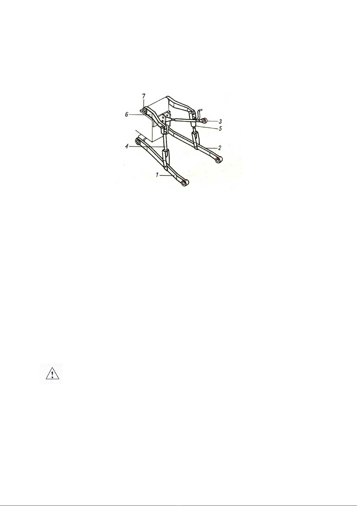
3.1. Attaching the tractor
•The attachment of the machine to the tractor must be made as specified,
remembering to secure the pins and to secure the suspension pins with split pins.
•When coupling the tractor to the cultivator, it is forbidden for persons to stay
between the machine and the tractor during this time.
•The tractor working with the cultivator must be fully operational. Coupling with a
tractor with a defective hydraulic system is prohibited.
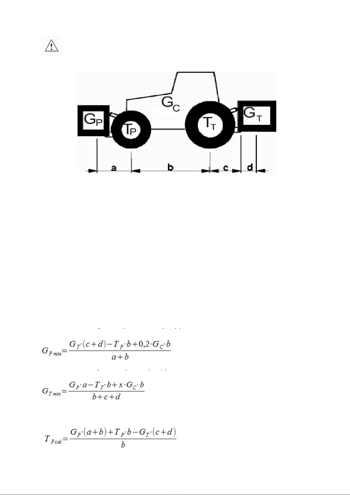
•Make sure that the tractor with the attached unit is stable, and the tractor
steerability and stopping power can be maintained. The load on the front axle
cannot drop below 20% of the total load on the tractor axle – use a set of front-
mounted weights (see section 4.1.).
•In the resting position, the machine, when uncoupled from the tractor, should
maintain a stable equilibrium.
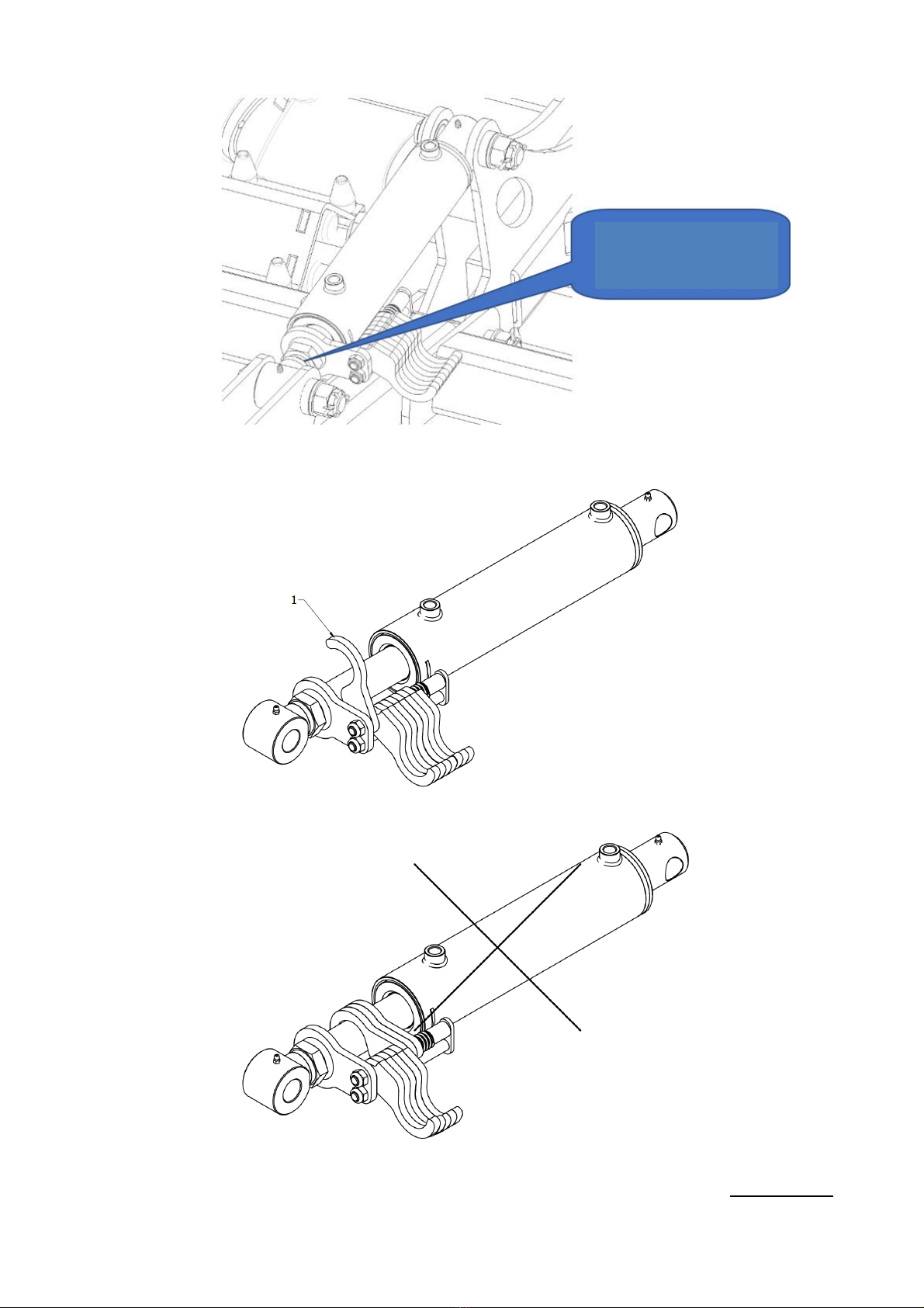
3.2. Hydraulic system
The hydraulic system is under high pressure - all precautions must be taken, in
particular:
•do not connect or disconnect the hydraulic lines when the tractor's hydraulic system
is under pressure (hydraulics set to neutral),
•regularly check the condition of the connections and hydraulic lines,
•the unit must be taken out of service while the hydraulic fault is being rectified.
3.3. Tyres
•Tyre pressures must not exceed those recommended by the manufacturer and it is
forbidden to transport the machine at too low a pressure. This may damage the
machine and cause an accident on large uneven surfaces and when driving too fast.
•Significantly damaged tyres (particularly profile damage) must be replaced
immediately.