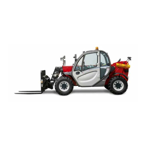
Manitou MUSTANG 1050RT X Series User manual

1050RT | 1050RT (EU) |
1050RT X-Series
Compact Track Loader
Operator’s Manual
50950436 Rev. H 05/21
Original Instructions

WARNING
This product can expose you to lead which is known to the
State of California to cause cancer and birth defects or
other reproductive harm. For more information go to www.
P65Warnings.ca.gov
Breathing diesel engine exhaust exposes you to chemicals
known to the state of California to cause cancer and birth
defects or other reproductive harm.
• Always start and operate the engine in a well-venti-
lated area.
• If in an enclosed area, vent the exhaust to the outside.
• Do not modify or tamper with the exhaust system.
• Do not idle the engine except as necessary.
For more information go to www.P65warnings.ca.gov/diesel.
WARNING

50940703/A1219
MANITOU EQUIPMENT AMERICA, LLC
WARRANTY
Manitou Equipment America, LLC under the GEHL®, MUSTANG by MANITOU®, MANITOU®, brand warrants
new MANITOU Group equipment to the Original Retail Purchaser to be free from defects in material and
workmanship for a period of twelve (12) months or Two Thousand Hours (2000 h) from the Warranty Start
Date which occur first.
MANITOU Group WARRANTY SERVICE INCLUDES:
Genuine XPRT parts and labor costs required to repair or replace equipment at the selling dealer’s business
location.
MANITOU Group MAKES NO REPRESENTATIONS OR WARRANTIES OF ANY KIND, EXPRESS OR IMPLIED
(INCLUDING THE IMPLIED WARRANTIES OF MERCHANTABILITY AND FITNESS FOR PARTICULAR
PURPOSE), EXCEPT AS EXPRESSLY STATED IN THIS WARRANTY STATEMENT.
ANY OF THESE LIMITATIONS EXCLUDED BY LOCAL LAW SHALL BE DEEMED DELETED FROM THIS WARRANTY;
ALL OTHER TERMS WILL CONTINUE TO APPLY.
SOME STATES DO NOT PERMIT THE EXCLUSION OR LIMITATION OF THESE WARRANTIES AND YOU MAY
HAVE GREATER RIGHTS UNDER YOUR STATE LAW.
MANITOU Group WARRANTY DOES NOT INCLUDE:
1. Transportation to selling dealer’s business location or, at the option of the Original Retail Purchaser,
the cost of a service call.
2. Used equipment.
3. Components covered by their own non- MANITOU Group warranties, such as tires, batteries, trade
accessories and engines.
4. Normal maintenance service and expendable, high-wear items.
5. Repairs or adjustments caused by: improper use; failure to follow recommended maintenance
procedures; use of unauthorized attachments; accident or other casualty.
6. Liability for incidental or consequential damages of any type, including, but not limited to lost
profits or expenses of acquiring replacement equipment.
7. Liability for consequential damages as an unfavorable environment (chemicals, dust, salt, corrosion
and erosion...)
8. Repairs completed outside MANITOU Group network and/or by personnel not trained by MANITOU
Group.
No agent, employee or representative of MANITOU group has any authority to bind of MANITOU group to
any warranty except as specifically set forth herein.
This agreement has been prepared in multiple languages, including but not limited to, English, Spanish, and
French (Canada). In the event of any inconsistency, the English version shall apply and be binding upon the
parties.

Printed in U.S.A. 1 50950436/H0521
TABLE OF CONTENTS
INTRODUCTION 5
Safety Symbol and Signal Words ..............................................5
Contents and Use of this Manual ...............................................5
Machine Orientation ........................................................6
Proper Machine Use .........................................................6
Service and Registration .....................................................6
Component Identication.....................................................8
List of Attachments .........................................................9
Using Attachments ........................................................10
Vibration Information.......................................................10
Fire Extinguisher ..........................................................11
Manufacturer Information ...................................................11
Indicator and Operation Symbols .............................................12
SAFETY 15
Safety Symbol and Signal Words .............................................15
Mandatory Safety Shutdown Procedure ........................................16
Before Starting ............................................................17
During Operation ..........................................................18
Applications with Load-Handling Devices .....................................20
Parking the Machine........................................................21
Electrical Energy ..........................................................21
Maintenance and Service Safety Practices ......................................22
Battery Hazards ...........................................................24
Fire Hazards ..............................................................24
Additional Safety Equipment ................................................25
Crystalline Silica Exposure ..................................................25
DECALS 27
General Information ........................................................27
Decal Locations ...........................................................27
SPECIFICATIONS 37
Fluids/Lubricants Types and Capacities ........................................37
Dimensions ...............................................................38
Payloads/Capacities ........................................................39
Weights ..................................................................40

Printed in U.S.A. 2 50950436/H0521
Coolant Compound Table....................................................40
Tracks ...................................................................40
Engine...................................................................40
Hydraulic System ..........................................................42
Sound Power/Pressure Levels ................................................42
Vibration Levels ...........................................................43
Standard and Optional Features ...............................................44
Common Materials and Densities .............................................45
INDICATORS AND CONTROLS 47
Display(s) ................................................................48
Switch Panel .............................................................54
Operator’s Seat ............................................................56
Throttle Controls ..........................................................56
Travel Controls ...........................................................57
Lift Arm Float.............................................................57
Emergency Lift Arm Lower ..................................................57
Parking Brake/ Hydraulics Transport Lockout ...................................57
Horn ....................................................................58
Cab Heat (Option) .........................................................58
Windshield Wiper/Washer ...................................................58
Beacon (Option) ...........................................................59
Battery Disconnect Switch...................................................59
OPERATION 61
Operational Checks/Pre-start Inspection ........................................61
Before Operation ..........................................................62
Seat Belt .................................................................62
Starting the Engine .........................................................63
Engine Warm Up ..........................................................65
Run-In Period .............................................................66
Stopping the Engine ........................................................66
Engine Stalling ............................................................66
Safety Interlock System (Hydraloc™)..........................................66
Travel Drive Operation. . . . . . . . . . . . . . . . . . . . . . . . . . . . . . . . . . . . . . . . . . . . . . . . . . . . . . 67
Back-up Alarm ............................................................72
Rubber Track Use Cautions and Tips ..........................................72

Printed in U.S.A. 3 50950436/H0521
.74
.75
.76
.79
.79
.79
. 80
.83
.88
.90
.94
.94
.95
.96
.97
.99
.99
101
.101
.101
.102
.104
.105
107
.107
.107
.109
.112
.112
114
116
117
118
118
Sprocket Tooth Wear and Track Life ..........................................
Lift Arm Operation........................................................
Lift Arm Lift Support ......................................................
Self-Leveling (Option) .....................................
Float Control.............................................................
Connecting/Disconnecting Attachments .......................................
Powering Attachments with Hydraulic Function. . . . . . . . . . . . . . . . . . . . . . . . . . . . . . . . .
Working with Buckets .....................................................
Working with Pallet Forks ..................................................
Diesel Particulate Filter (DPF) Regeneration Procedures..........................
After Operation...........................................................
Jump-Starting ............................................................
Lifting the Machine using a Crane............................................
Towing / Transporting the Machine...........................................
Loading and Transporting the Machine on a Transport Vehicle .....................
Long-Term Storage........................................................
Final Shutdown / Decommissioning ..........................................
LUBRICATION
Types of Lubricants .......................................................
Lubricant Capacities.......................................................
Lubrication Points and Decals ...............................................
Lubrication Schedule/Intervals .............................................
Filter Table .............................................................
MAINTENANCE
Maintenance Schedule ....................................................
Maintenance Interval .....................................................
Engine Maintenance......................................................
DPF Exhaust System Service...............................................
Fuel System Maintenance .................................................
Hydraulic System Maintenance ..............................................
Engine Cooling System ....................................................
Alternator/Fan Belt........................................................
Hydraulic Hose Maintenance................................................
Travel Motor Maintenance..................................................
Tracks ..................................................................119

Printed in U.S.A. 4 50950436/H0521
Electrical System .........................................................121
Windshield Washer Reservoir ...............................................123
Maintenance Log .........................................................124
Maintenance Log .........................................................125
Maintenance Log .........................................................126
Maintenance Log .........................................................127
TROUBLESHOOTING 129
Engine Troubleshooting ....................................................129
Indicator Lamp Troubleshooting .............................................131
Seal and Hose Troubleshooting ..............................................132
Hydraulic System Troubleshooting ...........................................132
Hydrostatic Travel Drive System Troubleshooting ...............................135
Electrical Troubleshooting ..................................................137
Error Codes..............................................................139
Index ...................................................................145
T orque Specications ......................................................149

Printed in U.S.A. 5 50950436/H0521
Chapter 1
INTRODUCTION
Safety Symbol and Signal Words
This manual and decals on the machine
warn of safety hazards and should be read
and observed closely.
Manitou Group, in cooperation with the
Society of Automotive Engineers, has
adopted this:
This symbol is used throughout this
operator’s manual and on the decals on the
machine. It identies potential safety haz-
ards, which, if not properly avoided, could
result in injury. When you see this symbol
in this manual or on the machine, you are
reminded to BE ALERT! Personal safety is
involved!
Signal Words
The word “DANGER” indicates an immi-
nently hazardous situation, that, if not
avoided, will result in serious injury or
death.
The word “WARNING” indicates a poten-
tially hazardous situation that, if not
avoided, could result in serious injury or
death.
The word “CAUTION” indicates a poten-
tially hazardous situation that, if not
avoided, may result in minor or moderate
injury.
IMPORTANT: The word “IMPORTANT”
indicates situations that can result in possible
damage to the machine.
NOTE: The word “NOTE” indicates special
or particularly useful information.
Contents and Use of this Manual
This operator’s manual provides informa-
tion about the safe and proper operation
and maintenance for the machine. Major
points of safe operation and maintenance are
detailed in the Safety chapter of this manual.
This manual also includes general trouble-
shooting and specication information about
the machine.
Follow the instructions in the Safety,
Operation and Maintenance chapters
concerning accident prevention regulations,
safety and occupational regulations, and
machine and trac regulations. Manitou
Americas is not liable for damage resulting
from the failure to follow these regulations.
Improper operation, inspection and
maintenance of the machine can cause
injury or death. Read and understand the
contents of this manual COMPLETELY
and become familiar with the machine
before operating it.
It is the owner’s or employer’s responsibility
to fully instruct each operator in the proper
and safe operation and maintenance of the
machine.

Introduction
6 Printed in U.S.A.
A storage location is provided behind the
operator’s seat for storing the operator’s
manual. After using the manual, return it to
the storage container.
This manual is considered a permanent
part of the machine and should be with
the machine at all times. If the machine is
resold, include this operator’s manual as part
of the sale.
Replace this manual promptly if it becomes
damaged, lost or stolen.
Some illustrations in this manual may show
doors, guards and shields open or removed
for illustrative purposes only. BE SURE all
doors, guards and shields are in their proper
operating positions BEFORE starting the
engine to operate the machine.
Because of ongoing product improvements,
information included in this manual may not
exactly match the machine. Manitou Group
reserves the right to modify and improve
products at any time without notice or
obligation.
Machine Orientation
“Right” and “left”, as described in this man-
ual, are determined from a position sitting in
the operator’s seat and facing forward.
Proper Machine Use
Improper use of the machine can result in
property damage, injury or death.
The machine is designed only for digging,
picking up, lifting, transporting and unload-
ing materials. Use of approved attachments
is also allowed. Using the machine in any
other way is considered contrary to the
intended use. Compliance with, and strict
adherence to, the conditions of operation,
service, and repair as specied by the manu-
facturer also constitute essential elements of
the intended use.
50950436/G0121
The machine was designed and built accord-
ing to the best available technology and
approved safety regulations in the countries
where it is sold. However, it is impossible
to completely safeguard against abusive,
improper use. The operator must always
consider potential safety risks and hazards
during operation. Accident prevention
regulations, all road trac regulations, and
all other generally recognized safety and
occupational medicine regulations must be
observed at all times.
The machine must be maintained in proper
operating condition. Any damaged or
malfunctioning parts must be repaired or
replaced immediately.
Any arbitrary modication carried out to the
machine may relieve the manufacturer of
liability for any resulting damage or injury.
Service and Registration
The wide Manitou Group dealership net-
work stands ready to provide any assistance
that may be required, including genuine
service parts. All parts should be obtained
from or ordered through your dealer.
When ordering service parts, provide
complete information about the part and the
quantity required. Also provide the model
and serial numbers of the machine. For
your safety and continued proper operation,
use only genuine service parts. Record the
model and serial numbers in the spaces
below for quick reference.

Introduction
Printed in U.S.A. 7 50950436/H0521
Machine Model and Serial
Numbers
Machine Model Number
_______________________________
Machine Serial Number
_______________________________
Component Serial Numbers
Engine Model Number
_______________________________
Engine Serial Number
_______________________________
Track Drive Motor Model Number
_______________________________
Track Drive Motor Serial Number
_______________________________
Hydraulic Pump Model Number
_______________________________
Hydraulic Pump Serial Number
_______________________________

Introduction
50950436/G01218 Printed in U.S.A.
Component Identication
Fig. 1 -
A
B
C
D
E
F
G
H
I
Machine Components
J
KK
L
M
N
O
P
Item Description
A Upright
B Lift Cylinder
C Tracks

Introduction
Printed in U.S.A. 9 50950436/H0521
Item Description
D Front Work Lights
E Hand holds
FLift Arm
G Auxiliary Hydraulic Couplers
H Tilt Cylinders
I Attachment Bracket
J Engine Cover
K Tail Lights
L Rear Work Lights
M Rear Door
N Roll-Over/Falling Object Protective Structure (ROPS/FOPS)
O Restraint Bar
P Lift Arm Support Device
Table 1 - Component Identication
List of Attachments
Dirt / Construction Buckets Weight Rated Operating Capacity
1372 mm/0.28 m³
(54.00 in./9.8 ft³
129 kg
(285 lbs.)
476 kg
(1050 lbs.)
1524 mm/0.31 m³
(60.00 in./11.0 ft³
138 kg
(305 lbs.)
467 kg
(1030 lbs.)
1549 mm/0.33 m³
(61.00 in./11.6 ft³
141 kg
(310 lbs.)
465 kg
(1026 lbs.)
Pallet Forks Weight Rated Operating Capacity
406.4 mm (16.00 in.) Forks with
Backrest Rating per EN474-3
213 kg
(470 lbs.)
319 kg
(704 lbs.)
508 mm (20.00 in.) Forks with
Backrest Rating per EN474-3
213 kg
(470 lbs.)
229 kg
(660 lbs.)
609.6 mm (24.00 in.) Forks with
Backrest Rating per SAE J1197
213 kg
(470 lbs.)
281 kg
(620 lbs.)
Table 2 - List of Attachments
The attachments determine how the machine is used.

Introduction
50950436/H0521 10 Printed in U.S.A.
Contact Edge Attachments (http://www.
edgeattach.com/) for information about
available attachments approved for use
with the machine.
Use of unapproved attachments could
result in serious injury or property
damage.
Contact Edge Attachments (http://www.
edgeattach.com/) before using attachments
or equipment not approved by Manitou
Americas. Use of non-approved attachments
or unauthorized modications is prohibited.
Using Attachments
Read all documentation provided with
attachments to learn how to safely operate
and maintain them.
Do not use the machine for any applications
or purposes other than those described in
this manual or manuals supplied with attach-
ments. Contact your dealer before using
attachments or equipment not approved
by Manitou Group. Use of non-approved
attachments or unauthorized modications is
prohibited..
Vibration Information
Compact construction equipment is gener-
ally used in harsh environments. This type
of usage can expose an operator to uncom-
fortable levels of vibration. It is useful to
understand exposure to vibration levels
when operating compact equipment and
what can be done to reduce vibration expo-
sure. As a result, equipment operation can be
more ecient, productive and safe.
An operator’s exposure to vibration occurs
in two ways:
•Whole-Body Vibration (WBV)
• Hand-Arm Vibration (HAV)
WBV issues are primarily addressed in this
manual, because evaluations have shown
that operation of mobile compact construc-
tion equipment on work sites typically
results in HAV levels less than the allowed
exposure limit of 2.5 m/s2. Member States
of the European Union must comply with
the Physical Agents (vibration) Directive,
2002/44/EC.
Eective control of vibration exposure
for an operator involves more than just
vibration levels on the machine. The work
site, how the machine is used, and proper
training all play important roles in reducing
vibration exposure.
Vibration exposure results from:
• Work site conditions.
• How the machine is operated.
• The machine characteristics.
Common causes of high WBV levels:
• Using a machine that is improper for
the task.
• Work site with potholes, ruts and
debris.
• Improper operating techniques, such as
driving too fast.
• Incorrect adjustment of the seat and
controls.
• Other physical activities while using
the machine.
Vibration Measurement and
Actions
The vibration directive places the responsi-
bility for compliance on employers. Actions
that should be followed by employers
include:
• Assess the levels of vibration exposure.
• Determine from this assessment if
operators will be exposed to vibration
levels above the limits stated in the
directive.

Introduction
Printed in U.S.A. 11 50950436/H0521
• Take appropriate actions to reduce
operator’s exposure to vibration.
• Provide operators with information
and training to reduce their exposure to
vibration.
• Keep good records and update opera-
tions and training on a regular basis.
If the assessment concludes that vibration
level exposure is too high, one or more of
the following actions may be necessary:
1. Train operators:
• Perform operations (accelerating, steer-
ing, braking, etc.) in a smooth manner.
• Adjust the controls, mirrors and seat
suspension for comfortable operation.
Do not make adjustments when the
machine is in use.
• Travel across the smoothest parts of the
work site and avoid ruts and potholes.
2. Choose proper equipment for the job:
• Use machines with the proper power
and capacity.
• Select machines with good suspension
seats.
• Look for controls that are easy to use.
• Ensure good visibility from the opera-
tor’s position.
3. Maintain the work site:
•Smooth ruts and ll potholes in trac
areas whenever possible.
• Clean up debris frequently.
•Vary trac patterns to avoid exposure
to rough terrain.
4. Maintain equipment. Check that seat
suspension and all controls work
smoothly and properly.
Vibration Levels
See “Vibration Levels” on page 43 for a
table listing typical whole-body vibration
levels for the machine.
Fire Extinguisher
An installation location for a re extin-
guisher is behind the operator’s seat (“Q” on
page 11).
IMPORTANT: Installation of a re
extinguisher according to DIN-EN 3 must be
performed by an authorized dealer.
IMPORTANT: Inspect the re extin-
guisher at regular intervals as recom-
mended by the re extinguisher equipment
manufacturer(s).
Fig. 2 -
Q
Location for Fire Extinguisher
NOTE: A re extinguisher is neither
included as standard equipment nor available
as an option from Manitou Group.
Manufacturer Information
Products described in this manual are manu-
factured by Manitou Equipment America.
NOTE: Not all models and options
described in this manual are available in all
areas.

Introduction
50950436/H0521 12 Printed in U.S.A.
Indicator and Operation Symbols
Power Off Power On Engine Start Battery Charge Electrical Power
Worklight w/Tail
Lights Worklight Safety Alert Hazard Flasher Fasten Seatbelt
Horn Read Operator’s
Manual Volume - Full Volume - Half Full Volume - Empty
Parking Brake Engine Air Filter Engine Oil Engine Oil Filter Engine Oil
Pressure
Fuel Filter Engine
Temperature Hydraulic System Hydraulic Oil
Temperature Hydraulic Oil Filter
Grease Lubrication
Point
Glow Indicator
Lamp Diesel Fuel Clockwise
Rotation
Counterclockwise
Rotation
Fast Slow Ride Control Engine Malfunction
Shutdown Bucket - Float
Bucket - Rollback Bucket - Dump Lift Arm - Lower Lift Arm - Raise Service Hours
Low Fuel Alarm Master Light
Switch Position Lights Engine Speed
Control
%
Engine Power
Percentage

Introduction
Printed in U.S.A. 13 50950436/H0521
Remove Key Crush Hazard Pinch Point Crush Hazard Hot Surface
Hazard
Rotating Fan -
Keep Away Safety Lock Auxiliary
Hydraulics Flow Fan Lift Arm Float
Hitch Lock Hitch Unlock Heater Engine
Temperature
Critical Error
Warning
Engine Error Code Lock Unlock Front Window
Washer
Rear Window
Washer
Front Window
Wiper
Rear Window
Wiper Beacon Regeneration Regeneration
Inhibit
Aftertreatment
Error

Introduction
50950436/H0521 14 Printed in U.S.A.
Legal Notices
Software IP
Any extraction, decompilation, modication, duplication, or distribution of onboard soft-
ware is strictly prohibited. Manitou shall have no liability for and hereby disclaims all direct
and indirect liability for the consequences resulting from the use of any prohibited onboard
software. Contact MANITOU for any request to correct or adapt onboard software for the
purposes of interoperability.
Data Privacy
Manitou connected machines are equipped with boxes that collect technical data concern-
ing the machines (such as geolocation, operating, and component data). This data, which is
organized, processed, and enriched by Manitou’s own algorithms and knowledge, constitutes
a protected database in accordance with Article L.341-1 of the French Intellectual Property
Code.
It is strictly forbidden to access all or part of this database or to use this data (whether or not
intentional) without Manitou’s express authorization. In the event that Manitou authorizes an
individual to access all or part of this database, Manitou, as producer of this database, only
grants the user a personal, non-exclusive, and non-transferrable right to use the database, and
only via access to a computer platform hosted on a server owned or controlled by Manitou.
In any case, the following activities are strictly prohibited:
- any extraction, reproduction, representation, reuse by making available to the public, diu-
sion, or transfer, whether permanent or temporary, on any support, and by any means and in
any form whatsoever, of all or a qualitatively or quantitatively substantial part of the contents
of the database,
- any extraction, reproduction, representation, reuse by making available to the public,
diusion, transfer, or repeated and systematic extraction of qualitatively or quantitatively
insubstantial parts of the contents of the database when these operations clearly exceed the
conditions of normal use of the database by the user of the machine for his or her own needs,
- any use of a means of circumventing technical measures for the protection of databases or
the source code of the software embedded in the boxes, in accordance with Article L.331-5 of
the Intellectual Property Code.
In the event that the above measures are absolutely essential to enable the use of the software,
in accordance with its intended purpose, or to obtain the information necessary for interoper-
ability with other independently created software, the user must rst contact Manitou, which
may, at its sole discretion, take necessary measures or provide access to only the information
strictly necessary for interoperability.
Any violation of these prohibitions is likely to constitute an infringement for which Manitou
may take legal action.

Printed in U.S.A. 15 50950436/H0521
Chapter 2
SAFETY
Safety Symbol and Signal Words
This manual and decals on the machine warn
of safety hazards and should be read and
observed closely.
Manitou Group, in cooperation with the
Society of Automotive Engineers, has adopted
this:
This symbol is used throughout this operator’s
manual and on the decals on the machine. It
identies potential safety hazards, which, if
not properly avoided, could result in injury.
When you see this symbol in this manual or on
the machine, you are reminded to BE ALERT!
Personal safety is involved!
Signal Words
The word “DANGER” indicates an
imminently hazardous situation, that, if
not avoided, will result in serious injury
or death.
The word “WARNING” indicates a
potentially hazardous situation that,
if not avoided, could result in serious
injury or death.
The word “CAUTION” indicates a
potentially hazardous situation that,
if not avoided, may result in minor or
moderate injury.
IMPORTANT: The word “IMPORTANT”
indicates situations that can result in pos-
sible damage to the machine.
NOTE: The word “NOTE” indicates spe-
cial or particularly useful information.
•Before operating the machine, rst read
and study the safety information in this
manual. Be sure that anyone who oper-
ates or works on the machine is familiar
with the safety precautions. This includes
providing translations of the warnings
and instructions for operators who are not
uent in reading English.
• It is essential that operators be thor-
oughly trained in the safe operation of the
machine and load handling. Such training
should be presented completely to all new
operators and not condensed for those
claiming previous experience.
• Operators must not be physically or
mentally impaired or under the inuence
of drugs or alcohol. Do not allow minors
or unqualied personnel to operate the
machine, or to be near the machine unless
they are properly supervised. It is recom-
mended that the operator be capable of
obtaining a valid motor vehicle operator’s
license.
• Do not use the machine for any applica-
tion or purpose other than those described
in this manual, or in manuals supplied
with any attachments used with the
machine.
• Use of the machine is subject to certain
hazards that cannot be eliminated by

Safety
16 Printed in U.S.A.
mechanical means, but only by exercising
intelligence, care and common sense.
Examples of such hazards include but
are not limited to: hillside operation,
overloading, load instability, poor main-
tenance, operating too fast for conditions,
and using the machine for a purpose for
which it was not intended or designed.
• Manitou Group always takes operator’s
safety into consideration during the
design process. Guards and shields are
provided, which protect the operator
and bystanders from moving parts and
other hazards. Operators must be alert,
however, because some areas cannot be
guarded or shielded without preventing or
interfering with proper operation.
• Certain applications may require optional
safety equipment. Users must evaluate the
work- site hazards and equip the machine
and the operator as necessary. The infor-
mation in this manual does not replace
any applicable safety rules and laws.
Before operating the machine, learn the
rules and laws for the local area. Make
sure the machine is equipped as required
according to these rules/laws.
• Remember that some risks to your
health may not be immediately apparent.
Exhaust gases and noise pollution may
not be visible, but these hazards can cause
permanent injuries.
• Some photographs in this manual may
show doors, guards and shields open or
removed for the purposes of illustration
only. Be sure all doors, guards, shields
and panels are secured in the proper oper-
ating positions before starting the engine
to operate the machine.
Mandatory Safety Shutdown
Procedure
BEFORE cleaning, adjusting, lubricating,
fueling, or servicing the machine, or leaving it
unattended:
50950436/H0521
1. Bring the machine to a complete stop
on a level surface. If the machine must
be parked on a slope, park across the
slope and chock the tracks to prevent
movement.
2. Be sure all working equipment and/or
attachments are stopped and the auxiliary
valve is in neutral.
3. Empty the attachment and lower the lift
arm and attachment to the ground.
4. Place forward/reverse drive into the
neutral position.
5. Apply the parking brake.
6. Move the throttle to the low-idle position
and allow the engine to cool.
7. Shut o the engine. Listen for evidence
that parts have stopped moving before
continuing.
8. Turn the ignition key to the ON/RUN
position and move the (multi-purpose)
joystick in all directions to verify the
hydraulic system is de-pressurized.
9. Press the auxiliary hydraulics pressure
relief switch to relieve pressure in the
auxiliary hydraulics circuit.
10. Turn o the ignition.
11. Unfasten the seat belt, remove the
ignition key and take it with you. Exit the
machine using the hand-holds.
12. Always turn the battery disconnect switch
to the “OFF” position when parking the
machine inside an enclosure.
ONLY when these precautions have been taken
can you be sure it is safe to proceed. Failure to
follow this procedure could result in death or
serious injury.
Before Starting
• Walk around the machine and inspect
it before using it. Refer to “Pre-Start

Safety
Printed in U.S.A. 17 50950436/H0521
Checks” on page 73.Look for damage,
loose or missing parts, leaks, etc. Repair
as required before using the machine.
• Do not remove or modify the Roll-Over
Protective Structure/Falling Object
Protective Structure (ROPS/FOPS)
unless instructed to do so in Manitou
Group-approved installation instructions.
Modications, such as welding, drilling
or cutting, can weaken the structure and
reduce the protection it provides. A dam-
aged ROPS/FOPS cannot be repaired – it
must be replaced.
•Unauthorized modications to the
machine can cause injury or death. Never
make unauthorized modications to
any part of the machine. Any machine
modication made without authorization
from Manitou Group could create a safety
hazard, for which the machine owner
would be responsible.
• For safety reasons, use only genuine ser-
vice parts. For example, using incorrect
fasteners could lead to a condition in
which the safety of critical assemblies is
dangerously compromised.
• Manitou Group equipment is designed
and intended to be used only with
Manitou attachments or Manitou-
approved attachments. To avoid possible
personal injury, equipment damage and
performance problems, use only attach-
ments that are approved for use on and
within the rated operating capacity of the
machine (see “Payloads/Capacities” on
page 41). Contact your dealer or Manitou
Group for information about attachment
approval and compatibility with specic
machine models. Manitou Group cannot
be responsible if the machine is used with
non-approved attachments.
• Optional kits are available through your
dealer. Because Manitou cannot antici-
pate, identify and test all of the attach-
ments owners may want to install on
their machines, please contact Manitou
Group for information on approval of
attachments, and their compatibility with
optional kits.
• Remove all trash and debris from the
machine every day, especially in the
engine compartment, to minimize the risk
of re.
• Always face the machine and use the
hand-holds and steps when entering and
exiting the machine. Do not jump o the
machine. See “Cab Entry and Exit” on
page 75.
• Never use ether starting aids. Engine
pre-heating is used for cold weather start-
ing. Engine pre-heating can cause ether
or other starting uid to detonate, causing
injury or damage.
• Walk around the machine and inspect it
before using it. Look for damage, loose
or missing parts, leaks, etc. Repair as
required before using the machine.
• Warn all nearby personnel before starting
the machine.
• Contact the proper local authorities for
utility line locations BEFORE starting to
dig. In North America, contact the North
American One-Call Referral System at
8-1-1 in the U.S., or 1-888-258-0808 in
the U.S. and Canada.
• Below-ground hazards also include water
mains, tunnels and buried foundations.
Know what is underneath the work site
before starting to dig.
• Before working near power lines (either
above-ground or buried cable type),
always contact the power utility and
establish a safety plan with them.
• If temperatures are changing, be cautious
of dark and wet patches when working or
traveling over frozen ground.
• Stay away from ditches, overhangs and
other weak support surfaces. Be sure the
surrounding ground has adequate strength
This manual suits for next models
2
Table of contents
Other Manitou Compact Loader manuals