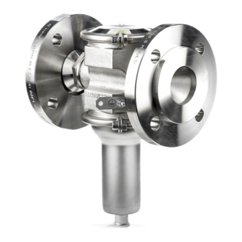
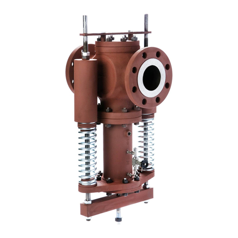
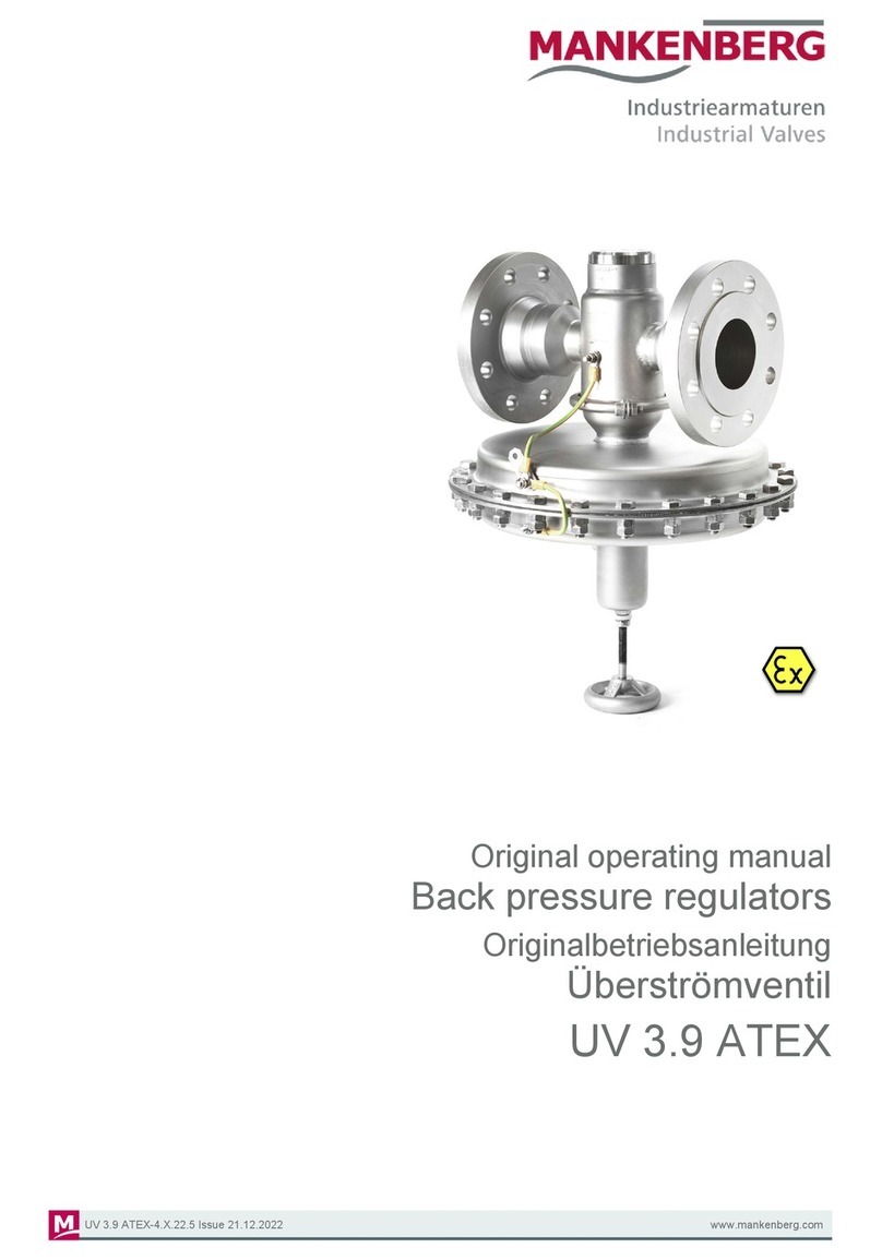
Mankenberg RP Series User manual

Original operating manual
Pilot-controlled pressure regulators
Originalbetriebsanleitung
pilotgesteuerte Druckregelventile
RP
RP-4.X.22 Stand 01.08.2022 www.mankenberg.com

2
RP-4.X.22 Stand 01.08.2022 www.mankenberg.com
Table of contents EN
1 Introduction................................................................................................................................................. 6
2 Intended use ............................................................................................................................................... 6
3 Marking of the fitting.................................................................................................................................. 8
4 Safety instructions ..................................................................................................................................... 8
4.1 General precaution .............................................................................................................................. 8
4.2 Special safety instructions for the plant operator................................................................................. 8
4.3 Special hazards ................................................................................................................................... 9
5 Transport and storage ............................................................................................................................... 10
6 Installation................................................................................................................................................... 11
6.1 General notes ...................................................................................................................................... 11
6.2 Installation preparations....................................................................................................................... 11
6.3 Installation steps .................................................................................................................................. 13
7 Pressure testing the pipeline section....................................................................................................... 14
8 Initial start-up.............................................................................................................................................. 15
9 Normal operation........................................................................................................................................ 16
10 Maintenance................................................................................................................................................ 17
11 Troubleshooting help................................................................................................................................. 18
12 Information on REACH and RoHS ............................................................................................................ 20
12.1 Declaration on the REACH Regulation 1907/2006.............................................................................. 20
12.2 Declaration on the RoHS Directive 2011/65/EU .................................................................................. 20
13 Further information .................................................................................................................................... 20
14 Know How ................................................................................................................................................... 20
14.1 Tusk ..................................................................................................................................................... 20
14.2 Selecting valve type and nominal diameter ......................................................................................... 21
14.3 Selecting rated pressure and valve material........................................................................................ 21
14.4 Selecting the setting range .................................................................................................................. 21
14.5 Selecting elastomer materials.............................................................................................................. 21
14.6 Flow velocity ........................................................................................................................................ 21
14.7 Sense line (control line) ....................................................................................................................... 21
14.8 Protecting your system ........................................................................................................................ 21
14.9 Protecting the backpressure regulator................................................................................................. 22
14.10 Valve seat leakage .............................................................................................................................. 22
14.11 Cut-off.................................................................................................................................................. 22
14.12 Stellited seat and cone ........................................................................................................................ 22
14.13 Leakage line ........................................................................................................................................ 22
14.14 Mounting position................................................................................................................................. 22
14.15 Start-up................................................................................................................................................ 22
14.16 Steam operation .................................................................................................................................. 23
14.17 Setting the pressure............................................................................................................................. 23

14.18 Maintenance ........................................................................................................................................ 23
14.19 Valves free of oil and grease or silicone.............................................................................................. 23
3
RP-4.X.22 Stand 01.08.2022 www.mankenberg.com

4
RP-4.X.22 Stand 01.08.2022 www.mankenberg.com
Inhaltsverzeichnis DE
1 Einleitung .................................................................................................................................................... 24
2 Bestimmungsgemäße Verwendung.......................................................................................................... 24
3 Kennzeichnung der Armatur ..................................................................................................................... 26
4 Sicherheitshinweise................................................................................................................................... 26
4.1 Allgemeiner Sicherheitshinweis ........................................................................................................... 26
4.2 Spezielle Sicherheitshinweise für den Betreiber.................................................................................. 26
4.3 Besondere Gefahren ........................................................................................................................... 27
5 Transport und Lagerung............................................................................................................................ 28
6 Einbau.......................................................................................................................................................... 29
6.1 Allgemeines ......................................................................................................................................... 29
6.2 Vorbereitung zum Einbau .................................................................................................................... 29
6.3 Schritte beim Einbau............................................................................................................................ 31
7 Druckprüfung des Rohrleitungsabschnitts ............................................................................................. 32
8 Erste Inbetriebnahme................................................................................................................................. 33
9 Normalbetrieb ............................................................................................................................................. 34
10 Wartung....................................................................................................................................................... 35
11 Hilfe bei Störungen..................................................................................................................................... 36
12 REACH- und RoHS-Auskunft .................................................................................................................... 38
12.1 Erklärung zur REACH-Verordnung 1907/2006.................................................................................... 38
12.2 Erklärung zur RoHS-Richtlinie 2011/65/EU ......................................................................................... 38
13 Weitere Informationen................................................................................................................................ 38
14 Know-How................................................................................................................................................... 38
14.1 Funktion ............................................................................................................................................... 38
14.2 Auswahl von Ventiltyp und Nennweite................................................................................................. 39
14.3 Auswahl von Nenndruck und Werkstoff............................................................................................... 39
14.4 Auswahl des Einstellbereichs .............................................................................................................. 39
14.5 Auswahl der Elastomere...................................................................................................................... 39
14.6 Strömungsgeschwindigkeit .................................................................................................................. 39
14.7 Steuerleitung........................................................................................................................................ 39
14.8 Absicherung Ihres Systems ................................................................................................................. 40
14.9 Schutz des Überströmventils ............................................................................................................... 40
14.10 Sitzdichtheit ......................................................................................................................................... 40
14.11 Absperrung .......................................................................................................................................... 40
14.12 Panzerung ........................................................................................................................................... 40
14.13 Leckleitung........................................................................................................................................... 40
14.14 Einbaulage........................................................................................................................................... 40
14.15 Inbetriebnahme.................................................................................................................................... 40
14.16 Betrieb mit Dampf................................................................................................................................ 41
14.17 Einstellung des Drucks ........................................................................................................................ 41

14.18 Wartung ............................................................................................................................................... 41
14.19 Öl- und fett- bzw. silikonfreie Geräte ................................................................................................... 41
5
RP-4.X.22 Stand 01.08.2022 www.mankenberg.com

Original operating manual
Pilot-controlled pressure regulators RP
6
RP-4.X.221 Issue 01.08.2022 www.mankenberg.com
1 Introduction
This manual is intended to assist users of a MANKENBERG pilot-controlled pressure-reducing or overflow valve
during installation, operation and maintenance. Read the manual thoroughly before installing or putting this
valve into service.
caution
Failure to follow the following instructions – particularly the cautionary and warning
notes – may lead to hazards and may invalidate the manufacturer's warranty.
MENKENBERG is at your servíce for any assistance and queries. See section Further
information [}20] for the addresses. Technical information is also available at
www.mankenberg.de.
Technische Informationen auch unter www.mankenberg.de
2 Intended use
A pilot-controlled MANKENBERG pressure-reducing valve DM.. is a device that is intended exclusively for
automatically regulating the outlet pressure of the medium (without any additional electrical/pneumatic energy)
after it has been installed in a pipeline system:
The force of the outlet pressure acts on a pilot valve. This controls the main valve so that if the outlet pressure
falls below the target value, the main valve opens further (or entirely) until the target value has been re-
established. If the outlet pressure rises above the target value, the main valve reduces or closes.
The pilot valve is integrated onto the main valve together with a restrictor assembly. The restrictor assembly
contains 2 or 3 restrictors for optimizing the regulation characteristics and 1 strainer. The desired target value
for the setting range must be set on the adjusting screw of the pilot valve.
A pilot-controlled MANKENBERG backpressure regulator UV.. is a device that is intended exclusively for
automatically regulating the inlet pressure of the medium (without any additional electrical/pneumatic energy)
after it has been installed in a pipeline system:
The force of the inlet pressure acts on a pilot valve. This controls the main valve so that if the inlet pressure falls
below the target value, the main valve is reduced (or closed) until the target value has been re-established. If
the inlet pressure increases above the target value, the main valve opens.
The pilot valve is integrated onto the main valve together with a restrictor assembly. The restrictor assembly
contains 2 or 3 restrictors for optimizing the regulation characteristics and 1 strainer. The desired target value
for the setting range must be set on the adjusting screw of the pilot valve.
note
A pilot-controlled pressure-reducing or backpressure regulator does not begin to operate until
Δp > 2bar; the valve does not react if the difference from the target value is lower thanthis. If
the control function is to operate at a lower differential pressure, special models or normal
pressure-reducing and overflow valves should be used.
note
A pilot-controlled pressure-reducing or backpressure regulator is not a safety valve. A suitable
valve must be present in the pipe section to limit any excess pressure.
note
After installation, the pilot valve must be adjusted to the desired inlet or outlet pressure. The
pressure gauges needed for this must not be mounted directly on the valve and are therefore
not included in the supply schedule. Suitable pressure display devices are needed on the plant
side.
MANKENBERG planning documents are available to give users precise assistance in selecting and designing
the appropriate fitting, e.g.:
In the section
<DM: Regulating valves for pressure>

Original operating manual
Pilot-controlled pressure regulators RP
7
RP-4.X.221 Issue 01.08.2022 www.mankenberg.com
<Design of pressure-regulating valves>
<Know-how on pressure-reducing valves / backpressure regulators>
<Type sheet RP.8..>
with technical data and tables of the setting ranges and the dimensions.
danger of
fatalities
These valves are no shut-off elements ensuring a tight closing of the valve. In accordance with
DIN EN 60534-4 and/or ANSI FCI 70-2 they may feature a leakage rate in closed position in
compliance with the leakage classes II – V:
Leakage class II (metal sealing double seat cone) = 0.5% Kvs values
Leakage class III (metal sealing cone) = 0,1 % Kvs values
Leakage class IV (PTFE seal cone) = 0,01 % Kvs values
Leakage class V (soft seal cone) = 1,8 x 10⁻⁵ x Δp x D* [l/h]
*D = seat diameter
Consequently, according to DIN EN ISO 2503 and DIN EN ISO 7291, a safety valve has to be
installed on the control side, which is dimensioned and adjusted in such a way that the lower
one of both pressure indications as mentioned below is relevant as response pressure:
- 1.5 times the maximum set pressure and/or (P out) of the valve (see nameplate), whichever
is the lowest
- PS out (see nameplate)
The response pressure of the safety valve should be abt. 40 % above the max. set pressure of
the pressure control valve.
Contrarily to the Pressure Equipment Directive, Annex 1, Paragraph 7.3, the short-term
maximum excess pressure is limited to 5 % of the max. allowable pressure (see above).
Failure to observe this regulation means danger to life and limb and may cause damage
to the pressure-regulating valve.
caution
Pressure-regulating valves are generally supplied with an open bonnet to facilitate
maintenance.
Valves with a sealed bonnet and leakage line connection can be supplied for toxic or
hazardous media. In this case the user must make sure that a suitable leakage line is installed.
caution
Service life
The valve is designed for quasi-static operation. 1000 full load variations between 0 bar and
PS max (PN or MAWP) are permitted, based on the entire service life of the pressure vessel;
see No. 1.4 AD 2000 sheet S 1.
Relevant pressure surges or dynamic loads are not permissible. The estimated service life is
approx. 5 years.
MANKENBERG valves are supplied as standard for screw-mounted or flange-mounted pipeline/tank
connections – also for special connections if required.
The upper limit of the permitted operating data is permanently marked on each fitting supplied.
In the following sections the two valve types DM and UV are combined under the heading of “Fitting” or
“Pressure-regulating valves” apart from a few sections that only apply to the valve types mentioned.

Original operating manual
Pilot-controlled pressure regulators RP
8
RP-4.X.221 Issue 01.08.2022 www.mankenberg.com
3 Marking of the fitting
Each fitting bears the following markings as a minimum:
For Marking Remark
Manufacturer MANKENBERG See section Further information [}20] for the
address
Fitting design Pressure-reducing + type or
Backpressure regulator + type
Design name as per accompanying
MANKENBERG data sheet
Nominal diameter e.g. DN or G and numerical
value
Numerical value for DN in [mm], for G in [inches]
Nominal pressure PN or Class and numerical
value
Zahlenwert für PN in [bar], für Class in [lbs/square
inch]
Numerical value for PN in [bar], for Class in [lbs/
square inch]. Unless otherwise indicated, all data
give the overpressure above atmospheric.
If 2 numerical values are given, these apply to the
inlet and outlet pressure.
Pressure range Pressure range and numerical
values
Max. permitted
temp.
Temperature and numerical
value
Temperatures above 50 °C entail a reduced
pressure resistance. This must be considered for
the corresponding material in accordance with the
DIN EN 1092 standard
Body material e.g. CrNiMo steel CrNiMo steel = high-alloy austenitic steel
Flow direction Indicated by an arrow
The markings (in the case of fittings made of deep-drawn stainless steel, they are etched into the body) should
neither be covered nor painted over, so that the fitting remains identifiable.
4 Safety instructions
4.1 General precaution
The same safety regulations apply to a fitting as to the system into which it is installed. These instructions only
give those safety recommendations that have to be additionally observed for the fitting.
4.2 Special safety instructions for the plant operator
The following requirements for the intended use of a fitting are not the responsibility of the manufacturer but
have to be guaranteed by the user:
» he fitting may only be employed for the purpose described in section Intended use [}6].
» The operator must ensure that the valve is only used with media for which both the valve and sealing
material are suitable.
» Only competent specialist personnel may install, operate and service the fitting. Competent as defined in
these instructions refers to persons who, because of their training, specialist knowledge and professional
experience, are capable of correctly assessing and properly executing the work with which they are
entrusted and of recognizing and rectifying hazards.

Original operating manual
Pilot-controlled pressure regulators RP
9
RP-4.X.221 Issue 01.08.2022 www.mankenberg.com
» The pipeline system must be properly designed and installed so that the fitting can be mounted and
operated without any tension.
» The fitting must be properly installed in the correct mounting position.
» The recommended installation, as described in the relevant MANKENBERG data sheet <DM 8...> or <UV
8...>, must be used for the pipeline section into which the pilot-controlled pressure-regulating valve is
installed. All control and/or leakage lines that are required on the pressure-regulating valve must be laid
properly, in accordance with the accompanying MANKENBERG data sheet.
» A pressure-regulating valve with an open spring must be installed in such a way that it presents no risk of
crushing to the operating personnel.
» The usual flow rates should not be exceeded in the pipeline section during continuous operation, and
abnormal operating conditions such as vibrations, unusually high flow rates, etc. should be avoided or – if
unavoidable – clarified with the manufacturer in advance.
» The prevailing operating conditions must comply with the limits of the design data stated in the
MANKENBERG order confirmation.
» The corrosion protection for the fitting must be adapted to the local environmental conditions.
» The fitting must not be coated with thermal insulation.
Detailed notes are provided on some of these prerequisites in the following sections.
4.3 Special hazards
danger of
fatalities
Before a fitting is removed from the system or before a fitting is dismantled but partially
remains in place, the pressure in the system on both the inlet and outlet side must be
completely reduced so that there is no uncontrolled flow of the medium out of the system.
In the case of toxic or hazardous media, the system must be completely drained before the
fitting is removed.
Caution is required with residues that might continue flowing.
danger of
being
crushed
Only valves with open spring:
It is necessary to ensure on site, by an appropriate installation or by providing safety devices
and/or positioning a clearly visible warning sign in accordance with the regulations of EN 292
(formerly accident prevention regulations), that effective protection is afforded against
objects catching on an exposed spring in the pressure-regulating valve.
If required, MANKENBERG will assist in selecting a suitable type with closed bonnet.
danger of
fatalities
If a pressure-regulating valve has to be dismantled:
The following must be observed at all costs:
First release the tension fully on the spring by turning the setting screw on the spring module
anticlockwise. When doing so, be sure to follow the notes in section Initial start-up
[}15]!
Then either seal off the two shut-off valves installed before and after the fitting in accordance
with the MANKENBERG installation recommendation and vent the pressure-regulating valve
or remove the pressure from the section of the system and then remove the fitting from the
pipeline.
caution
If a fitting is removed from a system with a toxic medium and is taken out of the plant:
it must be properly decontaminated before repair.

Original operating manual
Pilot-controlled pressure regulators RP
10
RP-4.X.221 Issue 01.08.2022 www.mankenberg.com
5 Transport and storage
A fitting must be handled, transported and stored with care:
» The fitting must be transported and stored in its protective packaging until it is installed.
caution
The fitting has moving internal parts.
Even packaged fittings should be transported smoothly without any shocks.
caution
In the case of a fitting that can no longer be transported by hand, the lifting gear must be
attached to a suitable position on the housing (branches).
Under no circumstances may the lifting gear be affixed to any attachments (adjusting
screw, handwheel or accessories).
caution
Pilot-controlled pressure-regulating valves in a sandwich design with slotted discs, in
particular, are especially sensitive to transport damage and dirt.
Die The protective packaging on the body must not be damaged during transport and
storage.
» When the fitting is stored prior to installation, it should be kept in closed rooms and protected against
harmful influences such as dirt, moisture and frost.
» In special cases, the fitting is supplied free of oil, grease or silicone and is marked accordingly. A fitting such
as this must not come into contact with oil/grease/silicone during storage and handling (particularly when
subsequently unpacked).
» A MANKENBERG fitting generally has functional and/or sealing parts made of elastomer materials. These
cannot be stored for an unlimited period.
note
ISO 2230 describes the storage conditions for elastomers in detail and specifies the
permissible storage period.
Functional and sealing parts must be replaced well before the storage period expires.
They are available from MANKENBERG as a “service set”. See also section Troubleshooting
help [}18].
note
MANKENBERG fittings of small and medium nominal diameters are largely made of stainless
steel (high-alloy CrNiMo steel).
If, under exceptional circumstances, fittings are stored in a unpacked state, they must be
protected against ferritic dust to avoid corrosion.
note
The fitting is generally not capable of standing alone:
The spring module may have a greater weight/volume than the basic body with its pipe
connections.
Handle with care so that the fitting does not tip over during transport/storage..
» Pressure-regulating valves are generally supplied with a slackened spring. The spring must not be
pretensioned by means of the adjusting screw until after it has been installed, during initial start-up.

Original operating manual
Pilot-controlled pressure regulators RP
11
RP-4.X.221 Issue 01.08.2022 www.mankenberg.com
6 Installation
6.1 General notes
The same installation regulations apply to a fitting as to the system into which it is installed. The following
additional notes apply:
» Section Transport and storage [}10] should also be observed during transport to the installation site.
» The installation site to allow perfect functioning of a fitting should be a section of pipe without any flow
disruptions, without any angles and without any restrictors or shut-off devices close to the fitting, either
upstream or downstream (optimum distance = 10 x DN). If this does not apply, the installation situation
should be checked with the plant operator and/or MANKENBERG.
» The statics of the pipeline must be designed so as to take account of the weight of the fitting – particularly
those with an eccentric mass. If required, the pipeline may have to be properly supported on both sides next
to the fitting (or at the fitting itself) – particularly in the case of fittings with a substantial mass and especially
if vibrations are to be expected in the system.
» When the fitting is supported, it is important to check that all functioning parts (adjusting screws, exposed
springs) remain capable of moving freely and are not blocked.
» The fitting must not be coated with thermal insulation.
caution
A fitting that is operated at a medium temperature above 130°C needs undisrupted removal of
heat if it is to function perfectly.
Failure to observe this instruction may cause damage to the fitting and hence in the
pipeline system as well.
» To protect internal functional parts (e.g. the seat) against damage and/or blockages, it may be necessary to
install a strainer and/or filter upstream of the fitting.
note
The mesh size of the sieve/filter for protecting against aggregates in the pipe section should be
selected by the plant operator according to the operating conditions.
Failure to observe this instruction may impair the function of the fitting and lead to
damage.
6.2 Installation preparations
» It is neccessary to ensure that a fitting is not installed unless its matches the operating conditions in terms of
function, pressure and temperature, range, body material as well as connection type and dimensions.
danger of
fatalities
No fitting may be operated that does not have a sufficient pressure and temperature range for
the operating conditions – see section Intended use [}6] and markings on the fitting.
The manufacturer MANKENBERG should be consulted in the case of any applications outside
of this range.
Failure to observe this regulation may mean danger to life and limb and may cause
damage to the pressure-regulating valve.
» Newly installed tanks and pipeline sections must be thoroughly rinsed and cleaned before commissioning.
» The corrosion protection for the fitting must be adapted to the local conditions.
» A pressure-regulating valve with an exposed spring must be installed in such a way that it presents no risk
of crushing to the operating personnel.

Original operating manual
Pilot-controlled pressure regulators RP
12
RP-4.X.221 Issue 01.08.2022 www.mankenberg.com
danger of
being
crushed
Only valves with open spring:
It is necessary to ensure on site, by an appropriate installation (e.g. not freely accessible) or
providing safety devices and/or positioning a clearly visible warning sign in accordance with
the regulations of EN 292 (formerly accident prevention regulations), that effective protection is
afforded against objects catching on an exposed spring in the pressure-regulating valve.
If required, MANKENBERG will assist in selecting a suitable type with closed bonnet.
Failure to observe this instruction: danger of crushing for the operating personnel
» Before installing a pressure-regulating valve, it is necessary to make sure that the pipeline section complies
with the recommended installation, as described in the relevant MANKENBERG data sheet. In particular, a
safety valve and a suitable strainer should be installed upstream of the fitting.
note
In some model series, a control line has to be laid between the pressure-regulating valve and
the pipeline by the customer – this is described in the above-mentioned recommended
installation.
Please note:
Only use control lines made of metal, not of plastic!
Distance of pressure-reducing valve/connection of control line to the pipeline 1 x DN upstream
of the valve and G10x DN downstream of the valve
Distance of backpressure regulator/connection of controllines to the pipeline ≥ 5x DN upstream
and downstream of the valve
Distance of vacuum control valve/connection to control line as for a pressure-reducing valve
DM or an backpressure regulator UV, according to design
When the medium is steam, lay the control line at an angle, with the gradient falling towards
the valve, see (catalogue) section <Know How Pressure-reducing valves%gt;
The control line should match the connection on the fitting.
Adjustable restrictors are integrated in the restrictor assembly to avoid vibrations.
The pressure-regulating valve should first be adjusted during the initial start-up by setting the adjusting screw
on the spring module to the operating conditions – see section Initial start-up [}15]. However, it is necessary
to ensure before installation that there is sufficient room for the appropriate socket or open-jawed spanner
above/below the adjusting screw.
important
note
As a general rule, pressure-regulating valves should be installed in horizontal lines so that the
pilot valve points upwards.

Original operating manual
Pilot-controlled pressure regulators RP
13
RP-4.X.221 Issue 01.08.2022 www.mankenberg.com
6.3 Installation steps
Fittings should only be finally unpacked at the installation site and inspected for damage prior to assembly.
Damaged fittings must not be installed.
It is necessary to ensure that the covers have been removed from all the connection branches before
installation.
The fitting should be inspected to ensure that it is clean. Interior parts must be free of liquid (e.g. condensate): if
necessary, connecting branches should be cleaned before installation with clean compressed air.
The type and dimensions of the line or tank connections must match the fitting to be installed and be flush with
the connecting surfaces of the fitting as well as in a parallel plane to the fitting itself.
If the fitting is marked with an arrow on the housing, the flow in the pipe section must match the marked
direction of flow.
caution
If installed in the opposite direction to the arrow, the fitting will not perform its intended
function.
The fitting mist be installed without any tension. In the case of an already installed system, the geometry of the
pipeline must match the face-to-face length of the fitting.
note
It is necessary to ensure that even under operating conditions no tension from the pipeline
is transferred to the fitting.
note
A MANKENBERG fitting made of "high grade" or "high grade pure" stainless steel (austenite,
e.g. 1.4404 or 1.4435) does not need any surface protection for normal environmental
atmosphere and for normal weather conditions.
External parts of the fitting made of low-alloy or non-alloy materials that are supplied ex-works
with a primer have to be provided with a suitable coating by the customer.
caution:
Never paint over the marking(s) of the fitting (either etched into the body or on nameplate).
A pressure-regulating valve should first be adjusted during the initial start-up by setting the adjusting screw on
the pilot valve to the operating conditions – see section Initial start-up [}15].
In addition, the following applies to the pipeline connection:
with flanges:
note
The sealing surfaces on the body of the fitting are formed in accordance with the
MANKENBERG order confirmation. The accompanying flange seals are generally not
included in the MANKENBERG supply schedule..
During installation, centre the fitting by means of the flange screws on the mating flange before the screws are
tightened.

Original operating manual
Pilot-controlled pressure regulators RP
14
RP-4.X.221 Issue 01.08.2022 www.mankenberg.com
with screw-mountings:
note
The connecting surfaces on the body of the fitting are formed in accordance with the
MANKENBERG order confirmation. The required seals are generally not included in the
MANKENBERG supply schedule.
with welding ends:
Properly performed welding must ensure that no significant tension is transferred to either the section of pipeline
or the body of the fitting.
Under no circumstances may the body of the fitting exceed the temperature marked on it; otherwise the sealing
and functional parts will be damaged and the whole fitting will become unserviceable..
caution
When a fitting with a body made of "high grade" or "high grade pure" deep-drawn parts (visible
on the body connection with clamp rings) is welded, the welding joint must be carried out with
special care; it is recommended that the body should be kept cool with a damp cloth..
Failure to observe this instruction may cause distortion of the fitting body: even 0.1 mm of
permanent distortion in the seat region may render the fitting unserviceable..
7 Pressure testing the pipeline section
The fitting has already been pressure-tested by the manufacturer. The following points should be observed
when conducting a pressure test on a pipeline section with a pressure-regulating valve installed:
Pressure-reducing valve:
the test pressure must not exceed 1.5 times the max. adjustable outlet pressure.
e.g. a setting range of 4 to 8 bar gives a max. permitted test pressure of 8 bar x 1.5 = 12 bar.
The test pressure on the inlet pressure side is determined by the pressure marked on the body.
Backpressure regulator:
the test pressure must not exceed 1.5 times the max. adjustable inlet pressure.
e.g. a setting range of 4 to 8 bar gives a max. permitted test pressure of 8 bar x 1.5 = 12 bar.
In keinem Fall darf der Prüfdruck das 1,5-fache des Wertes überschreiten, der mit “PN“ oder “Class“ am
Gehäuse gekennzeichnet ist.
Vacuum control valve:
the test pressure must not exceed 1.5 times the max. adjustable pressure. The information described above
should be observed according to whether a pressure-reducing or backpressure regulator forms the basis
for the vacuum control valve.
If any leakage occurs on the fitting, section Troubleshooting help [}18] should be observed.
note
If the pipe section is flushed and/or dried after assembly or pressure testing, it is necessary to
make sure that the fitting has not been damaged by corrosion or excessively high temperature.

Original operating manual
Pilot-controlled pressure regulators RP
15
RP-4.X.221 Issue 01.08.2022 www.mankenberg.com
8 Initial start-up
danger of
fatalities
No fitting may be operated that does not have a sufficient pressure and temperature range for
the operating conditions – see section Intended use [}6] and markings on the fitting. The
manufacturer MANKENBERG should be consulted in the case of any applications outside of
this range.
Failure to observe this regulation may mean danger to life and limb and may cause
damage to the pressure-regulating valve.
The fitting is supplied with no tension on the spring – hence no defined operating pressure has been set in the
factory. During initial start-up, the valve must be adjusted to the system parameters. The adjusting screw on the
pilot valve should be tensioned for this purpose:
Clockwise rotation (when looking onto the adjusting screw) has the following effect:
on the pressure-reducing valve: the outlet pressure increases.
on the backpressure regulatorthe inlet pressure increases.
The target value to be set by means of the adjusting screw shall be defined by the operator of the system and
must be calibrated with the aid of a pressure gauge on the plant side (or some other pressure monitoring
device).
caution
When looking onto the adjusting screw:
Never fully remove the adjusting screw (by rotating it anticlockwise).
Do not block the adjusting screw in the position of maximum tension (when rotating it
clockwise).
danger
At the beginning of or shortly after the initial start-up, the sieve or the filter insert of any
installed strainer/filter should be cleaned in order to avoid blocking the strainer/filter.
caution
After the initial start-up:
Check the seals on screw-mounted parts of the body and reseal if necessary. If required, ask
MANKENBERG for the tightening torques.
Observe the relevant notes in section Troubleshooting help [}18].
To speed up the filling and emptying of the control chamber during start-up, restrictors D1, D2 and D3 should be
fully opened. To vent the pressure-reducing valve, slightly undo the venting screw on the restrictor assembly.
Do not unscrew it completely. Tighten the venting screw again when no more air comes out.
Restrictors D1, D2 and D3 are for adjusting the control valve to the operating conditions of the system.
Basic setting (factory-set):
control restrictor D1 opened by approx. 1 revolution
damping restrictors D2, D3 opened by approx. 2 revolutions
caution
Never fully close the restrictors!

Original operating manual
Pilot-controlled pressure regulators RP
16
RP-4.X.221 Issue 01.08.2022 www.mankenberg.com
9 Normal operation
A properly designed pressure-regulating valve works automatically and does not need any form of auxiliary
energy.
note
To obtain optimum regulating accuracy, the desired operating pressure should be in the upper
part of the setting range of the pressure-regulating valve. This is described in detail in the “DM”
Section of the MANKENBERG catalogue under “Calculation of Pressure Regulators”.
In case of doubt, contact MANKENBERG Service – see Section Further information [}20] for
addresses.
danger of
fatalities
It is necessary to ensure that the materials selected for the parts of the fitting in contact with
media are suitable for the media in use. The manufacturer accepts no liability for any damage
due to corrosion by aggressive media on parts made of unsuitable materials.
Failure to observe this regulation may mean danger to life and limb and may cause
damage to the pipeline system and to the fitting.
caution
The fitting has functional parts that have to remain capable of moving easily. Make sure that
both the external springs and inner parts in contact with the medium cannot freeze nor become
blocked by dirt. Observe the maintenance intervals.
Failure to observe this instruction may cause damage to the pipeline system and to the
fitting.
danger
In some series a control line is laid between the pressure-regulating valve and the pipeline –
see section General notes [}11].
Damage to this control line may result in danger to life and limb and may impair the
function of the pressure-regulating valve or even lead to complete failure.
danger
Pilot-controlled pressure-regulating valves are designed for the operating location in
accordance with the order. The restrictor assembly has 2 or 3 integrated restrictors with which
the operating response to pressure fluctuations can be influenced.
Incorrect setting of the restrictors can cause damage in the system.
note
Pilot-controlled pressure-regulating valves are designed for the operating point in accordance
with the order. This operating point may occasionally be changed by the customer by means of
the adjusting screw. However, the setting of the adjusting screw must not be permanently
altered (e.g. by adding a valve actuator)
Failure to observe this instruction may cause damage to the pressure-regulating valve.
It is recommended that the fitting should be inspected to ensure that it is functioning correctly after each new
start-up.

Original operating manual
Pilot-controlled pressure regulators RP
17
RP-4.X.221 Issue 01.08.2022 www.mankenberg.com
10 Maintenance
The automatic function of the fitting requires maintenance to ensure that it continues to operate perfectly. It is
important for maintenance work to take place in a planned manner at periodic intervals.
The maintenance plan is a recommendation by the manufacturer MANKENBERG, which should be
supplemented by practical experience gained by the user under the prevailing operating conditions.
MANKENBERG shall assume no liability resulting from improper maintenance and/or repairs.
Sample plan for maintenance work
Type of maintenance Work to be performed Period 1)
Check function Check whether function is fulfilled as per section
Intended use [}6].
At least 1x per week
Check seal on the
body, the pipe
connection and the
control lines
Visual inspection At least 1x per month
Grease sliding points Grease external sliding points with a corrosion-
protection lubricant
At least 4x per year
Monitor exposed
spring
Visual inspection:
if necessary, remove any dirt/corrosion 2)
At least 2x per year
If installed upstream of
the fitting:
clean strainer
According to the manufacturer's instructions Depends on the
contamination of the
medium
Preventive
maintenance Dismantle fitting, see sction Troubleshooting help
[}18].
Visual inspection of diaphragm and functional parts.
Replace all parts of the maintenance set 3)
At least 1x per year
Check safety valve According to the manufacturer's instructions At least 1x per year
1) See comment at the beginning of this section: The time intervals are guides which should be adapted to
match the prevailing operating conditions, the properties of the medium in the system and the user's
experience.
2) Caution danger of crushing: shut down the valve for cleaning purposes!
3) Request maintenance set and replacement instructions from MANKENBERG.
danger
During maintenance work (apart from visual inspections) the relevant recommendations and
warning notes in section Troubleshooting help [}18] should be observed.
Failure to observe this warning may mean danger to life and limb and may cause
damage to the pipeline system and to the fitting.

Original operating manual
Pilot-controlled pressure regulators RP
18
RP-4.X.221 Issue 01.08.2022 www.mankenberg.com
When a fitting that has previously been dismantled is being put back into service, the fitting should be checked
for proper sealing capacity and function as well as correct adjustment of the adjusting and functional
components!
11 Troubleshooting help
Be sure to observe section Safety instructions [}8] uwhen rectifying faults.
Spare parts must be ordered with all the details on the nameplate. Only original parts from the manufacturer
MANKENBERG may be installed.
MANKENBERG experts are available to help in rectifying faults as quickly as possible. See section Further
information [}20] for the addresses.
note
If functional or corrosion damage is detected during maintenance or after a fault:
consult MANKENBERG to find out whether a more suitable fitting is available or whether the
damaged part can be supplied in a better-suited material.
Type of fault Action
Leakage at a connection body
parts (flange or clamp ring):
reseal connection
Tighten the screws clockwise (tighten flange screws crosswise).
If the screws of the body connection have to be loosened or removed (=
unscrewing in the anticlockwise direction):
danger of fatalities
To prevent any risk for operating personnel, make sure that this repair
measure is only carried out on a section of pipe that is not under pressure.
Take note of section Special hazards [}9] and then section Installation
[}11].
Leakage on the bonnet
The valve must be repaired
The control mechanism (diaphragm, piston or bellows) is defective and
has to be replaced:
Repair necessary, as described further below.
danger of fatalities
The pretensioned spring must be fully relaxed before a fitting is
dismantled!
To prevent any risk for operating personnel, make sure that this repair
measure is only carried out when the fitting is not under pressure. Take
note of section Special hazards [}9].

Original operating manual
Pilot-controlled pressure regulators RP
19
RP-4.X.221 Issue 01.08.2022 www.mankenberg.com
Type of fault Action
Functional fault
Leakage at the seat means
the set inlet or outlet pressure
is not correctly regulated:
Clean the functional parts
A foreign object may be jammed in the seat and be preventing proper
sealing:
fully release the tension on the DM pressure-reducing valve spring
ully release the tension on a UV backpressure regulator spring
on a vacuum control valve, observe the above remarks according to the
design
so that the valves open and foreign objects can be flushed out.
If the functional fault cannot be rectified in this way:
cleaning is necessary: the valve must be dismantled
Danger of fatalities
The pretensioned spring must be fully relaxed before a fitting is
dismantled!
To prevent any risk for operating personnel, make sure that this repair
measure is only carried out when the fitting is not under pressure. Take
note of section Special hazards [}9].
When the valve is not under pressure, take off the spring module by
releasing the clamp rings (or the screw connection) and dismantle the
diaphragm (or piston/bellows) and functional parts for cleaning. Here all
parts of the maintenance set should be renewed.
Afterwards, assemble the fitting and readjust it, as described under
section Initial start-up [}15].
Functional fault
Cleaning alone – see above –
cannot rectify the fault:
The fitting must be repaired
If during cleaning it is found that the control mechanism (diaphragm, piston
or bellows), the cone or other functional parts are damaged:
Repair necessary: damaged parts have to be replaced..
If the repair is to be carried out in the customer's workshop:
make a note of all data according to the markings on the fitting and order
the spare parts and necessary instructions from MANKENBERG. See
section Further information [}20] for addresses.
or:
Send the fitting to the manufacturer for repair. See section Further
information [}20] for the addresses.

Original operating manual
Pilot-controlled pressure regulators RP
20
RP-4.X.221 Issue 01.08.2022 www.mankenberg.com
12 Information on REACH and RoHS
12.1 Declaration on the REACH Regulation 1907/2006
Some Mankenberg products contain a candidate substance (SVHC) according to the Candidate List (REACH-
VO, Article 33); as of January 2021.
The following products have components that contain candidate substances (SVHC) in a concentration of more
than 0.1 mass percent:
Product name Name (CAS N°) Components involved Further information for
safe use
Pressure reducing valve
DM 4
Lead (7439-92-1) guide bush, lantern Since lead is a fixed
alloy component and
therefore no exposure is
expected, no additional
information on safe use
is necessary.
Pressure reducing valve
DM 401
Lead (7439-92-1) piston flange
Pressure reducing valve
DM 502
Lead (7439-92-1) seat, cone, disc, piston
guide
Pressure reducing valve
DM 701
Lead (7439-92-1) piston flange, bushing, lower
part
Back pressure regulator
UV 1.2
Lead (7439-92-1) disc, piston guide
Back pressure regulator
UV 1.6
Lead (7439-92-1) lantern
Back pressure regulator
UV 3.2
Lead (7439-92-1) piston guide
12.2 Declaration on the RoHS Directive 2011/65/EU
Mankenberg products are no electrical or electronic equipment and therefore do not fall within the scope of the
RoHS Directive 2011/65/EU (RoHS, Article 4, para. 1 or Annex I).
13 Further information
You can obtain these instructions, the MANKENBERG data sheets quoted as well as further information –
including English language versions – from the following addresses:
Mankenberg GmbH
Spenglerstrasse 99
D-23556 Lübeck
Phone +49-451 -8 79 75 0
Fax +49-451 -8 79 75 99
E-Mail [email protected]
www.mankenberg.de
14 Know How
14.1 Tusk
Backpressure regulators control an adjustable constant pressure upstream of the valve. A spring keeps the
valve close. As the inlet pressure rises the valve opens
This manual suits for next models
1
Table of contents
Languages:
Other Mankenberg Controllers manuals
