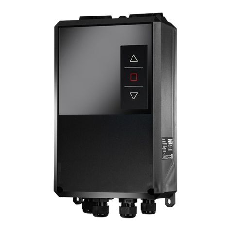
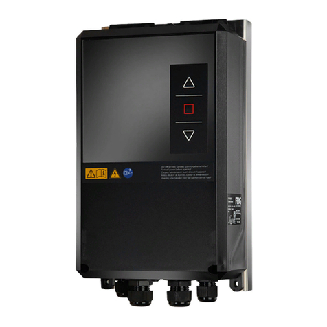
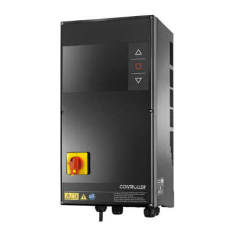
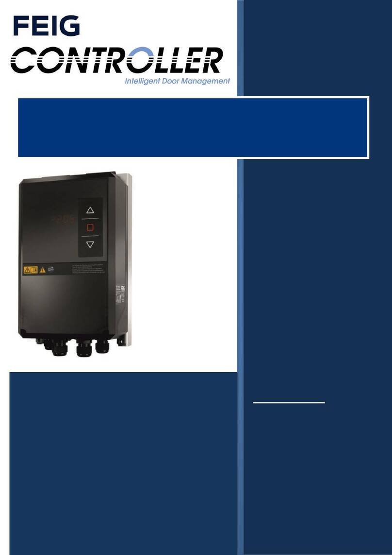
Feig Electronic TST FUF2 Series User manual

DE ACHTUNG! WICHTIGE SICHERHEITSANWEISUNGEN!
Den Hinweisen auf Seite 3 dieser Montageanleitung ist Folge zu
leisten.
GB ATTENTION! IMPORTANT SAFETY INFORMATION!
Follow the instructions on page 3 of this manual.
FR ATTENTION! IMPORTANTES INDICATIONS DE SÉCURITÉ!
Les instructions de la page 3 de cette notice de montage doivent
être observées strictement,
NL LET OP! BELANGRIJKE VEILIGHEIDSINSTRUCTIES!
Volg de instructies op pagina 3 van deze montagehandleiding
op.
IT ATTENZIONE! INDICAZIONI SULLA SICUREZZA
IMPORTANTI!
Prestare attenzione alle note alla pagina 3 delle presenti
istruzioni di montaggio.
ES ATENCION INDICACIONES IMPORTANTES DE SEGURIDAD!
Deben seguirse las indicaciones detalladas en página 3 de
estas instrucciones de montaje.
Attention
Important Safety
Information
These instructions must
be observed to ensure
personal safety.
Store these instructions
safely.
Assembly instructions
Installation, commissioning, utilization and maintenance
TST FUF2
Versions:
-A / -C / -F
TST FU3F
Versions:
-A / -C / -F

TST Assembly instructions FUF2 / FU3F -A/-C/-F
FEIG ELECTRONIC GmbH page 8 of 94 FUxF_Montageanleitung_GB_13.docx
1 General description and intended use
The device described below is an electronic control system for motor-driven industrial or commercial doors in
accordance with EN 13241. A fully integrated frequency converter with power output stage can gently control
the door with variable opening and closing speeds. The control system TST FUF2 is designed to handle
electrical induction motors with a power consumption of up to 2.2 kW and a 230 V supply. The control
system TST FU3F is designed to handle electrical induction motors with a power consumption of up to 5 kW
and a 400 V supply.
In addition to controlling the motor that drives the door, the controller can be used for the following tasks:
Positioning the door at and between its final positions (open, close and intermediate positions)
To control the drive to run at different speeds (integrated frequency converter)
Evaluation of the security sensors on the door (e.g. safety edge monitoring, pull-in protection, etc.)
Evaluation of additional safety equipment on the door (e.g. photo eyes, light curtains, etc.)
Evaluation of control circuits at the door (e.g. pull switch, radio, inductive loops, etc.)
Evaluation of emergency stop controls
Electronically protected 24V low-voltage power supply for sensors and control devices
230 V power supply to external units
Safe 24 V brake (with monitoring in accordance with EN 13849)
Control of application-specific outputs (such as relays for door position reporting)
Generation and output of diagnostic messages
Configuration of application-specific parameters for different levels of access of the different user groups
Control of input/output expansion modules
o TST SFFE: plug-in module wireless remote control
o TST FSx: wireless Security System
o TST SURA: Safety edge evaluation board
o TST SUVEK: plug-in module for inductive loop detection
o TST RFUxK: universal display and input/output module
o TST RFUxFCOM: interface module for the lock-door applications, etc.
o TST RFUxIO-B/-E: universale input and ouput extension module
o Evaluation of interface signals for remote control, diagnosis and configuration of the
parameters of the door

TST Assembly instructions FUF2 / FU3F -A/-C/-F
FEIG ELECTRONIC GmbH page 9 of 94 FUxF_Montageanleitung_GB_13.docx
1.1 Intended use
The controller TST FUF2 is designed for the operation of an electrical induction motor with a power
consumption of up to 2,2 kW at 230 V supply. The controller TST FU3F is designed for the operation
of an electrical induction motor with a power consumption of up to 5 kW at 400 V supply any may only
be used for the operation of motor-driven doors and gates used in an industrial or commercial context
as defined by the door product standard DIN EN 13241.
Intended use includes compliance with all the specifications made in this assembly manual pertaining
to assembly, installation and commissioning, the applicable safety instructions and consideration of
the technical data.
The controller may only be operated with accessories authorized by FEIG ELECTRONIC GmbH.
All assembly, installation, commissioning and maintenance work performed on doors or gates or on
the drive units intended for the doors or gates are to be performed exclusively by qualified specialist
personnel as defined by the EC Machinery Directive. In particular, the following regulations require
compliance: VDE 0100, EN 50110, EN 60204, EN 60335 inc. part 103, the fire protection regulations,
accident prevention regulations and the applicable regulations for industrial doors (EN12453,
EN12978) and machine safety (EN ISO 13849, EN 62061).
1.2 Incorrect use
Incorrect use includes all use of the controller which is classed as non-intended use. .
This device is not intended for use by persons (including children) with limited physical, sensory or mental
abilities or lacking in experience and / or knowledge, unless they are supervised by a person responsible for
their safety or if they have received instructions regarding the use of the device. Children should be
supervised to ensure that they do not play with the device. Keep remote controls away from such persons.
Should the controller be subject to any use other than that described, the operating company will be liable for
the resulting damage. This applies to unauthorised alterations, modifications or programming to the controller
and its components as well as ignoring of warnings and safety instructions.
The following points in particular are classified as incorrect:
Use outside the specified assembly conditions and safety distances to the surroundings (place and
temperature).
Use in an explosive or easily flammable environment.
Use with defective parts.
Use with spare parts and extension boards, which have not been approved by FEIG ELECTRONIC
GmbH.
Use without safety devices.
1.3 Target group
This assembly manual is directed especially at persons involved with commissioning the controller
TST FUF2 or TST FU3F of FEIG ELECTRONIC GmbH.
The assembly and commissioning of the controller may only be carried out by officially qualified electricians
familiar with the safety standards of electrical drive and automation technology.
1.3.1 Personnel qualification
The TST FUF2 or TST FU3F FEIG ELECTRONIC GmbH controller may only be operated and maintained by
persons who comply with the requirements outlined here and are familiar with the safety standards of
electrical drive and automation technology.
All the person groups specified here must have read and understood this assembly manual before using the
controller.

TST Assembly instructions FUF2 / FU3F -A/-C/-F
FEIG ELECTRONIC GmbH page 12 of 94 FUxF_Montageanleitung_GB_13.docx
2 Safety information
Failure to observe the safety advisories can result in physical harm or damage to the controller.
When starting up and operating the controller, the following important safety advisories as well as the
installation and wiring notes must be strictly observed:
In accordance with the EC Machinery Directive only qualified personnel shall install the device on the doors or
at the drive units for doors or bring them together. The respective safety requirements for the entire door (machine)
must be aligned with the possibilities to meeting these safety requirements on the controller.
Improper integration of the controller into the door complex e.g. missing sensors, incorrect parameters, speed set
excessively high, etc. presents the risk that the door is operated without adequate safety precautions.
To comply with the safety function according to EN 13849, a position sensor certified for PL c must be used.
The commissioning of this controller is prohibited until it has been properly attached to the door that conforms
with the EC Machinery Directive and for which an EC declaration of conformity according to Annex II of the
Directive was obtained.
The following information describes standard applications that may not necessarily match the actual application. The
actual application is provided by the manufacturer of the door as part of the overall documentation or as part of the
operating instructions of the door.
Any installation, startup and maintenance work must only be performed by qualified specialists. In particular, the
following regulations must be observed: VDE0100, EN 50110 (VDE0105), EN 60204 (VDE0113), EN 50178 (VDE0160),
EN 60335 (VDE0700), fire protection codes, accident prevention regulations as well as the relevant regulations for
industrial doors and machine safety standards (EN ISO 13849, EN 62061)(ZH1/494, EN12453, EN12978)
This device is not intended for use by persons (including children) with limited physical, sensory or mental abilities or with
a lack of experience and / or knowledge, unless they are supervised by a person responsible for their safety or if they
have received instructions on the use of the device. Children should be supervised to ensure that they do not play with
the device. Keep remote controls away from such persons.
A device mark (nameplate with name and address of the manufacturer, serial number, model number, supply voltage
and temperature range) must be applied by the user.
The example of the warning label must be attached to the motor near the motor terminal board.
ATTENTION

TST Assembly instructions FUF2 / FU3F -A/-C/-F
FEIG ELECTRONIC GmbH page 14 of 94 FUxF_Montageanleitung_GB_13.docx
3 Installation of the controller
ATTENTION
IMPORTANT INSTRUCTIONS FOR SAFE INSTALLATION!
Observe all instructions; incorrect installation can result in serious injuries!
When installing the controller, the system must be turned off.
The controller may be opened only if all the poles of the supply voltage have been turned offIt is not
permitted to turn on or to operate the controller when it is open.
Disconnect all supply circuits before opening the housing for access to the terminals.
Before the installation, check the controller for transport or other damages. Under some conditions a
damaged controller may result in significant consequential damage to the controller as well as hazards to
the user.
The controller must never be operated with a damaged membrane keypad or Display window. Damaged
keypads and Display windows must be replaced.
Do not touch any electronic parts, in particular the components of the processor circuit. Electronic
components can be damaged or destroyed by electrostatic discharge.
Before opening the cover of the enclosure, ensure that no drilling swarf can fall into the housing from the
cover.
When installing the controller it is important to ensure that it is not subject to mechanical stresses.
Unused cable entries must be sealed to maintain the requirements of IP65.
Ensure that the cable entries are not subjected to mechanical stresses, in particular tensile stresses.
The controller must never be operated without the CEE-plug except when the supply voltage can be cut
all poles by an installed main switch. The main switch and the CEE-plug must be within easy reach.
A not rotating motor is no indication of the galvanic isolation from the power grid! The line supply
connection terminals, motor terminals and terminals for the brake resistor can still carry dangerous
voltages, e.g. under stop or emergency stops.
If the supply cable is damaged, it must be replaced by the manufacturer or another qualified person in
order to avoid danger (like connection type Y EN 60335-1)
When moving the door in deadman mode, ensure that the operator has an unobstructed view of the door
area. In this mode, safety equipment such as safety edge and photo eye may have been defeated. If this
is not possible for structural reasons, you must ensure that this mode is only accessible to appropriately
trained personnel or that the feature is disabled altogether.
To prevent damage to the keypad, do not use pointed objects to operate the keys. The keypad is only
designed to be operated by human fingers.
Depending on the type of the door it may be necessary that the door can only be operated when it is
within visual range. In these cases, no remote control (e.g. wireless) may be used to issue commands.
It is important to ensure that the controller is installed with the wall spacers that are supplied to guarantee
that the power stage can dissipate heat as necessary.
environments with highly flammable substances (e.g. carpentry).
When the controller is installed in an additional housing, e.g. in a barrier housing, care must be taken to
provide a sufficient volume of air around the controller. This must be at least 0,02 m3.
Should cooling not be sufficient, an additional heat sink may be inserted between the controllers housing
and the additional housing to dissipate the heat to the outside.
WARNING

TST Assembly instructions FUF2 / FU3F -A/-C/-F
FEIG ELECTRONIC GmbH page 24 of 94 FUxF_Montageanleitung_GB_13.docx
4 Electrical connection
ATTENTION
Any wiring, testing and maintenance work on an
open controller shall only be performed when
power has been turned off. Pay particular
attention to the points shown under "Safety
information".
The controller must never be operated while it is
open.
When the controller has been turned off,
dangerous voltage levels are still present for up
to 5 minutes.
During the downtime, no isolation exists between
the amplifier module and the motor terminal.
Touching electronic components is dangerous
due to residual voltages.
Never operate the controller while the cover is
removed.
When the installation was completed, check that
the system was configured correctly and that the
safety system works properly.
The controller may be opened only if all the poles
of the supply voltage have been turned off. The
controller must never be operated while it is
open.
Never operate the controller without having
connected the protective earth conductor. The
absence of a protective earth conductor will
result in hazardous voltages on the controllers
housing caused by terminal capacitances. The
RFI filters integrated into the controller may
increase the leakage current up to a max. of 7
mA (see DIN EN 60335-1 section 16.2). Prior to
delivery, the manufacturer will test individual
units in this respect
Hazardous voltages remain stored in the DC-bus
capacitors for up to five minutes after power has
been turned off. The discharge time until voltages
fall below 60VDC is a maximum of 5 minutes.
Touching internal controller components within
this discharge time is hazardous.
A defective switching power supply can
considerably increase the discharge time of the
DC-bus capacitors before reaching a voltage less
than 60VDC. In this case, discharge times of up
to 10 minutes may be possible.
The processor circuit is galvanically connected to
the power line. Important: when taking
measurements on the processor circuit, do not
use test equipment with PE reference to the
measuring circuit.
The controller must never be operated with a
damaged membrane keypad or Display window.
Damaged keypads and Display window must be
replaced. To prevent damage to the keypad, do
not use pointed objects to operate the keys. The
keypad is only designed to be operated by
human fingers.
If the potential free contacts of the output relays
or other terminals are supplied by an external
voltage, i.e. dangerous voltages that are still
present after switching off the controller or
disconnecting power, you must attach a
suitable warning sign to the housing.
ATTENTION
You must disconnect all
supply circuits before opening the housing
to access the terminals"
When moving the door in deadman mode,
ensure that the operator has an unobstructed
view of the door area, since in this mode safety
equipment such as safety edge and photo eyes
are defeated.
Parameter settings and the speed as well as
the operation of the safety devices must be
checked. Parameter settings and the function of
the safety devices must to be checked.
TST Assembly instructions FUF2 / FU3F -A/-C/-F
FEIG ELECTRONIC GmbH page 19 of 94 FUxF_Montageanleitung_GB_13.docx
3.2 Version in plastic housing FUxF-xH
The plastic version of the control consists of the mounting frame incl. printed circuit board, which is inserted
into the housing. The housing has the following dimensions:
179
89,5
210
Figure 4 Dimensions and drilling plan FUxF-xH Plastic housing

TST Assembly instructions FUF2 / FU3F -A/-C/-F
FEIG ELECTRONIC GmbH page 20 of 94 FUxF_Montageanleitung_GB_13.docx
3.3 Versions in steel or stainless steel housing
Steel and stainless steel housing variants are also available.
The housing has the following dimensions:
3.3.1 300 x 400 mm
300
255
T = 200
Figure 5: Housing 300 x 400

TST Assembly instructions FUF2 / FU3F -A/-C/-F
FEIG ELECTRONIC GmbH page 26 of 94 FUxF_Montageanleitung_GB_13.docx
4.1 Power supply connection
4.1.1 TST FUF2
PE
NL
fuse 16A / K- Type
NL PE
Figure 9: Connecting the power cable

TST Assembly instructions FUF2 / FU3F -A/-C/-F
FEIG ELECTRONIC GmbH page 27 of 94 FUxF_Montageanleitung_GB_13.docx
4.1.2 TST FU3F
Fuse
16A / K- Typ
L1 L2 L3 PE
PE
N
L1 L2 L3
N
Figure 10: Connecting the power cable
There is no line choke for TST FU3F-A available.

TST Assembly instructions FUF2 / FU3F -A/-C/-F
FEIG ELECTRONIC GmbH page 28 of 94 FUxF_Montageanleitung_GB_13.docx
4.2 Motor and brake connections
4.2.1 TST FUF2
3~
MAC
.
DC
Split ferrite
(742 727 22)
Split ferrite
(742 717 22 S)
30 31 32
Figure 11: Motor connection
When connecting the motor cable, the enclosed split ferrite (grey, Würth number: 742 727 22) must be
placed around the three wires (T1/T2/T3).
We recommend to place another split ferrite (black, Würth number: 742 717 22 S) around the complete
motor cable as close as possible to the door controller. The black split ferrite is not included in the scope of
delivery!

TST Assembly instructions FUF2 / FU3F -A/-C/-F
FEIG ELECTRONIC GmbH page 30 of 94 FUxF_Montageanleitung_GB_13.docx
4.2.2 TST FU3F
3~
MAC
.
DC
30 31 32
T1 T2 T3
Split ferrite
(742 727 22)
Split ferrite
(742 717 22 S)
Figure 12: Motor connection
When connecting the motor calbe, the enclosed split ferrite (grey, Würth number: 742 727 22) must be
placed around the three wires (T1/T2/T3).
In the A-Variant (2,2 kW) the wires T1/T2/T3 must be routed twice trough the split ferrite.
In the -C- and F-Version (4 und 5 kW) the wires must be routed one time through the split ferrite.
We recommend to place another split ferrite (black, Würth number: 742 717 22 S) around the complete
motor cable as close as possible to the door controller. The black split ferrite is not included in the scope of
delivery!

TST Assembly instructions FUF2 / FU3F -A/-C/-F
FEIG ELECTRONIC GmbH page 33 of 94 FUxF_Montageanleitung_GB_13.docx
4.3 Safety edge on the integrated evaluation
Various types of safety edges can be connected, for example:
Electrical safety edge with 1.2 k or 8.2 k terminating resistor.
Dynamical optical system
If one of these types of safety edges is connected when the door control system is switched on it
will be recognized automatically.
If no safety edge is connected, automatic closing of the door is not possible.
Use of additional types of safety edges is possible. Please contact the door manufacturer in this respect.
For the connection of the safety edge to a TST FU3F we recommend to place a split ferrite (black,
Würht Number: 742 717 22 S) around the wires of the safety edge (terminal 43 45) as close as possible to
the door controller. The black split ferrite is not included in the scope of delivery!
4.3.1 Connection of an optical safety edge
Spiral cable
Junction
box
41 42
Slack rope
switch
optional slip
door
brown
white
Receiver
Transmitter
green
45
44
43
42
41
Figure
14: Connection to an optical safety edge
If the safety edge type was not automatically detected, the optical safety edge on this input can be
activated via parameter P.460 = 5.

TST Assembly instructions FUF2 / FU3F -A/-C/-F
FEIG ELECTRONIC GmbH page 34 of 94 FUxF_Montageanleitung_GB_13.docx
4.3.2 Connecting an electrical resistance - safety edge
45
44
43
42
41
Spiral cable
Junction
box
43 44
41 42
Slack rope
switch
optional slip
door
Outside
white
Inside
brown
Figure 15: Connecting an electrical resistance - safety edge
If the safety edge type was not automatically detected, the resistive safety edge on this input can
be activated via parameter P.460 = 1
If no safety edge is connected, automatic closing of the door is not possible.

TST Assembly instructions FUF2 / FU3F -A/-C/-F
FEIG ELECTRONIC GmbH page 35 of 94 FUxF_Montageanleitung_GB_13.docx
4.4 Safety edge at the 2nd integrated evaluation (input 10)
This input is preset as digital input. Various types of safety edges can be connected, for example:
Electrical safety edge with 1.2 k or 8.2 k terminating resistor.
Dynamical optical system
Use of additional types of safety edges is possible. Please contact the door manufacturer in this respect.
4.4.1 Connect the optical safety edge at input 10
Spiral cable Junction
box
brown
white Receiver
Transmitter
green
Figure 16: Connection to an optical safety edge
In order to use an optical safety edge on input 10, the function of this input must first be
determined. For this purpose, parameters P.50A are used. For the setting refer to the parameter
list in Chapter input profiles.
Typically, this input is used as safety input during opening movement. For this example, parameter
P.50A = 1406 is set. Then the edge type of parameter P.5A2 must be set = 4.
It is important to first set parameter P.50A and then only parameter P.5A2

TST Assembly instructions FUF2 / FU3F -A/-C/-F
FEIG ELECTRONIC GmbH page 36 of 94 FUxF_Montageanleitung_GB_13.docx
4.4.2 Connecting a resistive - safety edge to input 10
8K2
outside
white
Inside
brown
brownwhite
Spiral cable
Figure 17: Connecting an electrical resistance - safety edge
In order to use to input 10 an optical safety edge first be determined the function of this input. For
this purpose, parameters P.50A are used. For the setting, refer to the parameter list in chapter
input profiles.
Typically, this input is used as safety input during opening movement. For example, parameter
P.50A = 1406 is set.
Then the edge type of parameter P.5A2 must be set. The following settings are available.
P.5A2 = 2: 8K2 safety edge, N.O.
P.5A2 = 3: 8K2 safety edge, N.C.
P.5A2 = 6: 1K2 safety edge, N.O.
P.5A2 = 7: 1K2 safety edge, N.C.
It is important to first set parameter P.50A and then only parameter P.5A2

TST Assembly instructions FUF2 / FU3F -A/-C/-F
FEIG ELECTRONIC GmbH page 41 of 94 FUxF_Montageanleitung_GB_13.docx
4.6.2 Absolute encoder TST PD
Absolute encoder TST PD is a multi-turn encoder. Due to a selectable transmission ratio, this encoder can
be used for both very fast (e.g. motor shaft) as well as very slow shafts (e.g. door shaft). The driving shaft
may execute more than a single revolution.
This encoder may also be equipped with the WICAB radio system to transfer the status of the safety edge
without a spiral cable. For this purpose, the stationary unit TST PD FSAS and the mobile unit TST FSAM or
TST FSBM are required.
+12 V
GND
RS485 B
RS485 A
12
34
M8 plug
with 4 poles
Wire 1: brown
Wire 3: blue
Wire 2: white
M8 4-pole
socket
36*
Min. IP65, gold
plated contacts
Wire 4: black
shield / PE
M8 plug
with 4 poles
35*
34*
33*
32*
31*
Figure 22: Absolute encoder TST PD

TST Assembly instructions FUF2 / FU3F -A/-C/-F
FEIG ELECTRONIC GmbH page 42 of 94 FUxF_Montageanleitung_GB_13.docx
4.6.3 Absolute encoder DES
Wire 1: Emergency stop
Wire 3: GND
Wire 6: 12 VDC
Wire 2: Channel B
31*
Terminal 31
Terminal 35
Terminal 36
Wire 4: Channel A Terminal 34
Wire 5: Emergency stop Terminal 32
Terminal 33
32*
33*
34*
35*
36*
1
2
3
4
5
6
Figure 23: Connection of absolute encoder DES

TST Assembly instructions FUF2 / FU3F -A/-C/-F
FEIG ELECTRONIC GmbH page 44 of 94 FUxF_Montageanleitung_GB_13.docx
4.6.5 Mechanical limit switches
36*
35*
34*
33*
32*
31*
Figure 27: Connecting cam switches
Alternately, the pre-limit switches can also be connected as normally closed contacts.

TST Assembly instructions FUF2 / FU3F -A/-C/-F
FEIG ELECTRONIC GmbH page 45 of 94 FUxF_Montageanleitung_GB_13.docx
4.7 Photo eye
71 72 73 74 75 76
Receiver
Photo eye
Figure 28: Photo eye connection
Other manuals for TST FUF2 Series
1
This manual suits for next models
11
Table of contents
Other Feig Electronic Controllers manuals

Feig Electronic
Feig Electronic OBID i-scan ID ISC.PR101 Installation and operating instructions

Feig Electronic
Feig Electronic TST FUZ2-A User manual

Feig Electronic
Feig Electronic TST WU User manual

Feig Electronic
Feig Electronic TST FU3E Installation manual

Feig Electronic
Feig Electronic TST FUZ2 User manual

Feig Electronic
Feig Electronic TST FUF2 Series User manual