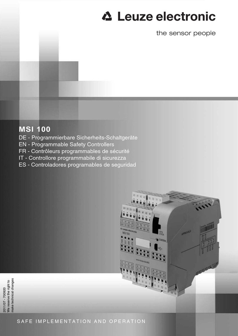
Leuze electronic MSI-MD-FBX User manual

SAFE IMPLEMENTATION AND OPERATION
Original operating instructions
EN 2017/03 - 50136367
We reserve the right to
make technical changes
MSI-MD-FBX
Muting Controller

© 2017
Leuze electronic GmbH & Co. KG
In der Braike 1
D-73277 Owen / Germany
Phone: +49 7021 573-0
Fax: +49 7021 573-199
http://www.leuze.com
Leuze electronic MSI-MD-FBX 2

Table of contents
Leuze electronic MSI-MD-FBX 3
Table of contents
1 About this document ............................................................................................5
1.1 Checklists................................................................................................................................ 5
1.2 Downloading the diagnostics software from the Internet ........................................................ 5
1.3 Used symbols and signal words ............................................................................................. 5
2 Safety .....................................................................................................................7
2.1 Intended use and foreseeable misuse....................................................................................7
2.1.1 Intended use........................................................................................................................7
2.1.2 Foreseeable misuse ............................................................................................................8
2.2 Necessary competencies........................................................................................................ 8
2.3 Responsibility for safety..........................................................................................................9
2.4 Disclaimer ............................................................................................................................... 9
3 Device description ..............................................................................................10
3.1 Device construction .............................................................................................................. 11
3.2 Display elements .................................................................................................................. 12
3.3 Connection technology ......................................................................................................... 13
4 Functions.............................................................................................................14
4.1 Timing controlled 2-sensor muting........................................................................................ 14
4.1.1 Timing controlled 2-sensor muting with Muting-enable .....................................................15
4.2 Overriding and muting restart ............................................................................................... 15
4.3 Error reset............................................................................................................................. 16
4.4 Restart .................................................................................................................................. 17
4.5 Acknowledging/resetting ....................................................................................................... 17
5 Applications ........................................................................................................18
5.1 Access guarding with timing controlled muting..................................................................... 18
6 Mounting..............................................................................................................19
6.1 Mounting the muting controller ............................................................................................. 19
6.1.1 Mounting in the UDC device column .................................................................................19
6.1.2 Mounting on the UDC device column................................................................................20
6.1.3 Mounting on the system ....................................................................................................20
6.2 Arrangement of the muting sensors...................................................................................... 20
6.2.1 Basic information...............................................................................................................21
6.2.2 Selecting optoelectronic muting sensors...........................................................................21
6.2.3 Minimum distance for optoelectronic muting sensors .......................................................21
6.2.4 Arrangement of the muting sensors for timing controlled 2-sensor muting ....................... 22
7 Electrical connection..........................................................................................25
7.1 Connecting the muting controller .......................................................................................... 25
7.2 Pin assignment of the machine interface.............................................................................. 27
7.3 Pin assignment of safety sensor........................................................................................... 27
7.4 Pin assignment of the acknowledgment unit ........................................................................ 28
7.5 Pin assignment of muting indicator....................................................................................... 28
7.6 Pin assignment of muting sensors........................................................................................ 29
7.7 Circuit diagram examples ..................................................................................................... 29
7.7.1 Timing controlled 2-sensor muting ....................................................................................29

Table of contents
Leuze electronic MSI-MD-FBX 4
8 Starting up the device - Configuration..............................................................30
8.1 Overview ............................................................................................................................... 30
8.2 Setting the operating mode................................................................................................... 31
9 Testing .................................................................................................................33
9.1 Before the initial start-up and following modifications........................................................... 33
9.2 Regularly by qualified persons.............................................................................................. 33
9.3 Periodically by the operator .................................................................................................. 34
9.3.1 Checklist – periodically by the operator.............................................................................34
10 Care, maintenance and disposal .......................................................................35
11 Diagnostics and troubleshooting......................................................................36
11.1 What to do in case of failure? ............................................................................................... 36
11.2 Error messages 7-segment display ...................................................................................... 36
12 Service and support ...........................................................................................40
13 Technical data .....................................................................................................41
13.1 General specifications .......................................................................................................... 41
13.2 Dimensioned drawings ......................................................................................................... 43
13.3 Dimensioned drawings - Accessories................................................................................... 43
14 Order guide and accessories.............................................................................45
14.1 Type overview....................................................................................................................... 45
14.2 Accessories........................................................................................................................... 45
15 EC Declaration of Conformity............................................................................47

About this document
Leuze electronic MSI-MD-FBX 5
1 About this document
1.1 Checklists
The checklists (see chapter 9 "Testing") serve as a reference for the machine manufacturer or supplier.
They replace neither testing of the complete machine or system prior to the initial start-up nor their periodic
testing by a competent person. The checklists contain minimum testing requirements. Depending on the
application, other tests may be necessary.
1.2 Downloading the diagnostics software from the Internet
ÄCall up the Leuze home page: www.leuze.com
ÄEnter the type designation or part number of the device as the search term.
ÄThe diagnostics software can be found on the product page for the device under the Downloads tab.
1.3 Used symbols and signal words
Tab.1.1: Warning symbols and signal words
Symbol indicating dangers to persons
Symbol indicating possible property damage
NOTE Signal word for property damage
Indicates dangers that may result in property damage if the measures for dan-
ger avoidance are not followed.
CAUTION Signal word for minor injuries
Indicates dangers that may result in minor injury if the measures for danger
avoidance are not followed.
WARNING Signal word for serious injury
Indicates dangers that may result in severe or fatal injury if the measures for
danger avoidance are not followed.
DANGER Signal word for life-threatening danger
Indicates dangers with which serious or fatal injury is imminent if the measures
for danger avoidance are not followed.
Tab.1.2: Other symbols
Symbol for tips
Text passages with this symbol provide you with further information.
Symbol for action steps
Text passages with this symbol instruct you to perform actions.
Symbol for action results
Text passages with this symbol describe the result of the preceding action.

About this document
Leuze electronic MSI-MD-FBX 6
Tab.1.3: Terms and abbreviations
AOPD Active Optoelectronic Protective Device
(Active Optoelectronic Protective Device)
Blanking Deactivation of the protective function of individual beams or beam areas with
monitoring for interruption
CS Switching signal from a control or a machine interface
(Controller Signal)
EDM Contactor monitoring
(External Device Monitoring)
FG Function group
(Function Group)
LED LED, display element in transmitter and receiver
MS1, MS2 Muting sensor1,2
MTTFdMean time to dangerous failure
(Mean Time To dangerous Failure)
Muting Temporary automatic suppression of the safety functions
OSSD Safety-related switching output
(Output Signal Switching Device)
PFHdProbability of a dangerous failure per hour
(Probability of dangerous Failure per Hour)
PL Performance Level
Reduced resolution Reduction of the detection capability of the protective field without monitoring
for tolerating small objects in the protective field
RES Start/restart interlock
(Start/REStart interlock)
Scan Consecutive scans of the protective field from the first to the last beam
Safety sensor System consisting of transmitter and receiver
SIL Safety Integrity Level
State ON: device intact, OSSD switched on
OFF: device intact, OSSD switched off
Locking: device, connection or control / operation faulty, OSSD switched off
(lock-out)

Safety
Leuze electronic MSI-MD-FBX 7
2 Safety
For mounting, operating and testing, this document as well as all applicable national and international stan-
dards, regulations, rules and directives must be observed. Relevant and supplied documents must be ob-
served, printed out and handed to affected persons.
ÄBefore working with the safety relay, completely read and understand the documents applicable to your
task.
In particular, the following national and international legal regulations apply for the start-up, technical in-
spections and work with safety relays:
• Machinery directive 2006/42/EC
• Low voltage directive 2014/35/EU
• EMC directive 2014/30/EU
• Use of work equipment directive 89/655/EEC supplemented by directive 95/63EC
• OSHA 1910 Subpart O
• Safety regulations
• Accident-prevention regulations and safety rules
• Ordinance on Industrial Safety and Health and employment protection act
• Product Safety Law (ProdSG and 9. ProdSV)
NOTICE
For safety-related information you may also contact local authorities (e.g., industrial inspec-
torate, employer's liability insurance association, labor inspectorate, occupational safety and
health authority).
2.1 Intended use and foreseeable misuse
DANGER
Electrically live systems pose a risk of electric shock!
ÄMake certain that, during all conversions, maintenance work and inspections, the system is
securely shut down and protected against being restarted.
ÄOnly have work on the electrical system and electronics performed by a competent person
(see chapter 2.2 "Necessary competencies").
2.1.1 Intended use
WARNING
A running machine may result in serious injury!
ÄMake certain that the safety relay is correctly connected and that the protective function of
the protective device is ensured.
ÄMake certain that, during all conversions, maintenance work and inspections, the system is
securely shut down and protected against being restarted.
Only if the safety relay is correctly connected and correctly started up is the protective function of the pro-
tective device ensured. To prevent misuse and resulting dangers, the following must be observed:
• These operating instructions are included in the documentation of the system on which the protective
device is mounted and are available to the operating personnel at all times.
• The safety relay is used as a safety monitoring device in combination with one or more safety sensors
for safeguarding danger zones or points of operation on machines and systems.
• The safety relay may only be used after it has been selected in accordance with the respectively appli-
cable instructions and relevant standards, rules and regulations regarding labor protection and safety at
work, and after it has been installed on the machine, connected, commissioned, and checked by a
competent person (see chapter 2.2 "Necessary competencies").
• The safety relay must only be connected and commissioned in accordance with its specifications (tech-
nical data, environmental conditions, etc.).

Safety
Leuze electronic MSI-MD-FBX 8
• The acknowledgment unit for unlocking the start/restart interlock must be located outside of the danger
zone.
• The entire danger zone must be visible from the installation site of the acknowledgment unit.
• When selecting the safety relay it must be ensured that its safety-related capability meets or exceeds
the required performance level PLr ascertained in the risk assessment (see chapter 13 "Technical
data").
• The machine or system control must be electrically influenceable so that a switch command sent by the
safety relay results in the immediate shutdown of the dangerous movement.
• The construction of the safety relay must not be altered. When manipulating the safety relay, the pro-
tective function is no longer guaranteed. Manipulating the safety relay also voids all warranty claims
against the manufacturer of the safety relay.
• The safety relay must be inspected regularly by a competent person to ensure proper integration and
mounting (see chapter 2.2 "Necessary competencies").
• The safety relay must be exchanged after a maximum of 20years. Repairs or the exchange of wear
parts do not extend the mission time.
2.1.2 Foreseeable misuse
Any use other than that defined under the “Approved purpose” or which goes beyond that use is consid-
ered improper use.
Alone, the safety relay is not a complete protective device. It is not suitable for use in the following cases:
• Applications in explosive or easily flammable atmospheres
• On machines or systems with long stopping times
2.2 Necessary competencies
The safety relay may only be configured, installed, connected, commissioned, serviced and tested in its re-
spective application by persons who are suitably qualified for the given task. General prerequisites for suit-
ably qualified persons:
• They have a suitable technical education.
• They are familiar with the relevant parts of the operating instructions for the safety relay and the operat-
ing instructions for the machine.
Task-specific minimum requirements for suitably qualified persons:
Configuration
Specialist knowledge and experience in the selection and use of protective devices on machines as well as
the application of technical rules and the locally valid regulations on labor protection, safety at work and
safety technology.
Mounting
Specialist knowledge and experience needed for the safe and correct installation and alignment of the
safety relay with regard to the respective machine.
Electrical installation
Specialist knowledge and experience needed for the safe and correct electrical connection as well as safe
integration of the safety relay in the safety-related control system.
Operation and maintenance
Specialist knowledge and experience needed for the regular inspection and cleaning of the safety relay –
following instruction by the person responsible.
Servicing
Specialist knowledge and experience in the mounting, electrical installation and the operation and mainte-
nance of the safety relay in accordance with the requirements listed above.

Safety
Leuze electronic MSI-MD-FBX 9
Commissioning and testing
• Experience and specialist knowledge in the rules and regulations of labor protection, safety at work and
safety technology that are necessary for being able to assess the safety of the machine and the use of
the safety relay, including experience with and knowledge of the measuring equipment necessary for
performing this work.
• In addition, a task related to the subject matter is performed in a timely manner and knowledge is kept
up to date through continuous further training ‑ Competent person in terms of the German Betrieb-
ssicherheitsverordnung (Ordinance on Industrial Safety and Health) or other national legal regulations.
2.3 Responsibility for safety
Manufacturer and operating company must ensure that the machine and implemented safety relay function
properly and that all affected persons are adequately informed and trained.
The type and content of all imparted information must not lead to unsafe actions by users.
The manufacturer of the machine is responsible for:
• Safe machine construction
• Safe implementation of the safety relay, verified by the initial test performed by a competent person
(see chapter 2.2 "Necessary competencies")
• Imparting all relevant information to the operating company
• Adhering to all regulations and directives for the safe commissioning of the machine
The operator of the machine is responsible for:
• Instructing the operator
• Maintaining the safe operation of the machine
• Adhering to all regulations and directives for labor protection and safety at work
• Periodic testing by a competent person (see chapter 2.2 "Necessary competencies")
2.4 Disclaimer
LeuzeelectronicGmbH+Co.KG is not liable in the following cases:
• Safety relay is not used as intended.
• Safety notices are not adhered to.
• Reasonably foreseeable misuse is not taken into account.
• Mounting and electrical connection are not properly performed.
• Proper function is not tested (see chapter 9 "Testing").
• Changes (e.g., constructional) are made to the safety relay.

Device description
Leuze electronic MSI-MD-FBX 10
3 Device description
The MSI-MD-FB muting controller is used as a safety-relevant link between an active opto-electronic pro-
tective device (AOPD) and the machine control. The muting controller enables muting through intentional
and temporary suppression of the protective function of the safety sensor, e.g., if objects are to be trans-
ported through the protective field.
The muting controller is mounted on machine parts or on a device column.
Safety sensors and muting sensors
The muting controller supplies the safety sensor and the muting sensors with 24V supply voltage.
The following safety sensors from Leuze electronic are released for connection to the muting controller:
• Safety light barriers of the MLD series
• Safety light curtains of the MLC series
NOTICE
The MSI-MD-FB muting controller is only released for the connection of the safety sensors from
Leuze electronic, e.g., MLC510 or MLD510.
The following muting sensors from Leuze electronic are released for connection to the muting controller:
• All common series: 3 series, 5 series, 8 series, 25 series, 46 series, 49 series, 96 series
Degree of protection and standards
The muting controller is designed in degree of protection IP67
The muting controller meets the following standards:
• Performance Level PLe in accordance with ENISO13849
• Safety Integrity Level SIL3 in accordance with IEC61508

Device description
Leuze electronic MSI-MD-FBX 11
3.1 Device construction
2
4
5
7
8
6
3
1
1 Mounting eyes for M4 screws
2 Cover for the DIP switch blocks for configuring the muting function and the Micro USB connection for reading
out diagnostics.
3 7‑segment display
4 Connection for the safety sensor
5 Connection for acknowledgment unit
6 Connections for muting sensors
7 Connection for external muting indicator
8 Connection to the machine interface (OSSDs and supply voltage)
Fig.3.1: Device construction of the muting controller

Device description
Leuze electronic MSI-MD-FBX 12
3.2 Display elements
The muting controller is equipped with the following display elements:
• LED indicators for the status of the assigned input signals
1
3
2
7
4
9
11
10
5
8
11
6
1 PWR LED
2 OSSD LED
3 RI LED
4 ERR LED
5 SC LED (1)
6 SC LED (2)
7 LC/LG LED
8 ML LED
9 RES LED (1)
10 RES LED (1)
11 LED MS1…MS4

Device description
Leuze electronic MSI-MD-FBX 13
Fig.3.2: LED indicators of the muting controller
LED Color Description
1 PWR Green Power (PWR)
2 OSSD Red OSSDs in the OFF state
Green OSSDs in the ON state
3 RI Yellow Restart active
Safety sensor on
The system is waiting for actuation of the acknowledgment unit
4 ERR Red Fault
5 SC Green Muting sensor alternative active
6 White Muting signal from the machine interface active
7 LC/LG OFF OSSDs of the safety sensor in the OFF state
Green OSSDs of the safety sensor in the ON state
8 ML Blue Muting indicators:
• OFF: no muting active
• Continuous light: muting active; safety sensor is bypassed by
means of muting
• Flashing: muting error; e.g., timeout
9 RES Yellow Acknowledgment unit pressed (reset signal)
10 Red Ready for reset (ReadyForReset signal)
The system is waiting for actuation of the acknowledgment unit
11 MS1…MS4 Green Muting sensor 1…4 active
3.3 Connection technology
NOTICE
Sockets and connectors that are not connected are to be covered with end caps!
ÄCover unconnected sockets and connectors with end caps.

Functions
Leuze electronic MSI-MD-FBX 14
4 Functions
By means of muting, the protective function of the safety sensor can be temporarily and properly sup-
pressed, e.g. if objects are to be transported through the protective field. The OSSDs of the muting con-
troller remain in the ON state in spite of interruption of one or more beams of the safety sensor.
Muting mode
The muting controller supports the following muting mode:
• Timing controlled 2-sensor muting (see chapter 4.1 "Timing controlled 2-sensor muting")
Muting timeout
Configurable time limit for the muting function (muting timeout):
• 20seconds
• 2minutes
• 10minutes
• 100hours
Muting timeout is set via the DIP switch blocks (see chapter 8 "Starting up the device - Configuration").
Muting sensors
Muting is initiated automatically and via mutually independent muting signals by muting sensors.
• Photoelectric sensors or scanning sensors can be connected to the muting controller as muting sen-
sors (see chapter 14 "Order guide and accessories").
• The state of a muting sensor is transferred on pin4 of the connection on the muting controller.
• The muting signals of the muting sensors are debounced:
• Pickup delay: 60ms
• Slow release: 300ms
NOTICE
Do not use muting signal MS1 via machine interface and local socket simultaneously!
ÄIf muting signal MS1 is used via the machine interface, MS1 must not be used simultane-
ously on the local socket.
4.1 Timing controlled 2-sensor muting
Muting is initiated automatically and via two mutually independent muting signals. These signals must be
active during the entire duration of the muting operation. Muting may not be initiated by a single sensor sig-
nal, nor may it be fully initiated by software signals.
The protective function of the entire protective field is deactivated during timing controlled muting.
MS2
MS1
1
2
3
1 Danger zone
2 Receiver of the safety sensor
3 Transmitter of the safety sensor
MS1 Muting sensor1
MS2 Muting sensor2
Fig.4.1: Arrangement of muting sensors for timing controlled 2-sensor muting in an exit application

Functions
Leuze electronic MSI-MD-FBX 15
MS1
MS2
< 4s < 0,3 s
MUTE
OSSD
PFF
< 4s > 4s
MS1 Muting signal1
MS2 Muting signal2
PFF Protective field free
MUTE Bridging through muting
OSSD OSSD status
Fig.4.2: Timing controlled muting - timing
The material can move in both directions. Often, an arrangement consisting of crossed beams from retro-
reflective photoelectric sensors is used (see chapter 6.2 "Arrangement of the muting sensors").
Timing controlled muting is used in the following cases:
• Moving-in applications: diffuse sensors in the danger zone detect the muting object through the protec-
tive field. The scanning range must be set to a sufficiently small value (see chapter 6 "Mounting").
• Exit applications: a photoelectric sensor in the danger zone works diagonally to the transport direction
together with a simultaneously activated machine interface signal, which derives from the drive of the
transport equipment, for instance (see chapter 6 "Mounting").
DANGER
Risk of death if installation is not performed correctly!
ÄFollow the instructions for the correct arrangement of the muting sensors (see chapter 6.2
"Arrangement of the muting sensors").
4.1.1 Timing controlled 2-sensor muting with Muting-enable
With the muting enable function, muting is enabled or disabled via an external muting enable signal. The
muting enable function is activated and deactivated via the DIP switch blocks (Starting up the device - Con-
figuration).
• If the muting enable signal is applied, a valid muting sequence initiates muting.
The muting enable signal must be applied at least 60ms before muting is initiated.
The muting enable signal must not be applied for more than 100hours.
• If the muting enable signal is not applied, no muting is possible, even with a valid muting sequence.
4.2 Overriding and muting restart
Following malfunctions or operationally related interruptions (e.g. power failure, violation of the simultaneity
condition during timing controlled 2-sensor muting on activation of the muting sensors), the system can be
manually reset with the acknowledgment unit and overridden.
• Muting override must only be initiated if at least one muting sensor is activated and the OSSDs of the
muting controller are switched off.
• Muting override is maintained only if at least one muting sensor is activated.
• The muting controller switches on its OSSDs when muting override is activated.
• For muting override or muting restart, the maximum muting timeout time is 10minutes.

Functions
Leuze electronic MSI-MD-FBX 16
WARNING
Unauthorized muting restart may result in serious injury!
ÄA qualified person (see chapter 2.2 "Necessary competencies") must observe the procedure
exactly.
ÄMake certain that the danger zone can be viewed from the acknowledgment unit and that
the entire process can be observed by the responsible person.
ÄBefore and during the muting restart, ensure that there are no people in the danger zone.
NOTICE
If the safety sensor or the muting controller responds with an error message, perform an error
reset (see chapter 4.3 "Error reset").
ÄPress and release the acknowledgment unit within 0.2 to 4s.
ÄPress the acknowledgment unit again and keep the acknowledgment unit pressed down.
ðThe muting controller switches on.
Both muting signals are activated:
The muting controller switches to muting mode.
A muting signal is activated:
Muting is initiated when the acknowledgment unit is released. The second muting signal must be activated
within a maximum of 4s in order to continue muting. If the second muting signal is not activated within this
time, muting is ended.
No muting signal is activated:
Muting is ended immediately even if the acknowledgment unit is not released.
Muting controller with muting enable; a muting signal is activated:
Muting is initiated when the acknowledgment unit is released. The second muting signal must be activated
within a maximum of 4s in order to continue muting. If the second muting signal is not activated within this
time, muting is ended.
Muting controller with muting enable; without extension of the muting timeout:
Overriding is only possible with acknowledgment unit permanently pressed down.
4.3 Error reset
If an internal or external error is detected by the safety sensor or the muting controller, the muting controller
switches to the interlock state.
To reset the safety circuit to the initial state, reset the muting controller via the reset signal.
• The reset signal can be set via the connected acknowledgment unit or via a component in the machine
interface.
• When overriding, the reset signal may only come from one source, i.e., either from the connection
socket of the acknowledgment unit or from the RES signal of the machine interface.
• Duration of the reset signal: 0.2s to 4s
Manual error reset
Reset signal via the connected acknowledgment unit
ÄPress and release the acknowledgment unit within 0.2 to 4s.

Functions
Leuze electronic MSI-MD-FBX 17
4.4 Restart
Following a violation of the protective field, the OSSDs are re-enabled via the reset signal.
• The restart can be started manually via the connected acknowledgment unit or via a component in the
control (Starting up the device - Configuration).
• The reset signal can be set via the connected acknowledgment unit or via a component in the machine
interface.
• Duration of the reset signal: 0.2s to 4s
4.5 Acknowledging/resetting
The ReadyForReset signal signals via the RES LED that the system is waiting for actuation of the acknowl-
edgment unit/reset button.
• The RES LED illuminates red if the OSSDs of the safety sensor are switched on and
the OSSDs of the muting controller are switched off.
• The RES LED flashes red if the system is expecting a muting restart, depending on the status of the
muting sensors. The OSSDs of the safety sensor must be switched off.
• The RES LED flashes red if a muting error occurs.
• If a muting error occurs together with a protected field violation, the OSSDs are switched off when
muting is terminated.
• If a muting error occurs in a free protective field, the OSSDs remain switched on.

Applications
Leuze electronic MSI-MD-FBX 18
5 Applications
5.1 Access guarding with timing controlled muting
3
2
1
4
1 Safety sensor
2 Muting controller
3 Muting sensors
4 Acknowledgment unit
Fig.5.1: Access guarding with timing controlled muting for an application with a pallet wrapping machine

Mounting
Leuze electronic MSI-MD-FBX 19
6 Mounting
ÄMount the muting sensors (see chapter 6.2 "Arrangement of the muting sensors").
ÄMount the muting controller (see chapter 6.1 "Mounting the muting controller").
ÄMake the electrical connection of the muting controller (see chapter 7 "Electrical connection").
NOTICE
ÄWhen mounting and aligning the safety sensor, observe the respective operating instruc-
tions.
6.1 Mounting the muting controller
You can mount the muting controller as follows:
• Mount in the UDC device column of the receiver of the safety sensor
• Mount on the UDC device column of the receiver of the safety sensor
• Mount on the system via M4 fastening holes
6.1.1 Mounting in the UDC device column
Mount the muting controller in the UDC device column of the receiver of the safety sensor, e.g., below the
receiver. The necessary mounting bracket is available as an accessory (see chapter 14 "Order guide and
accessories").
1
2
3
1 Mounting bracket BT-MSI-MD-FB-L
2 Muting controller
3 UDC device column
Fig.6.1: Mounting in the UDC device column

Mounting
Leuze electronic MSI-MD-FBX 20
6.1.2 Mounting on the UDC device column
Mount the muting controller on the side or on the rear of the UDC device column of the receiver of the
safety sensor. The required mounting plate is available as an accessory (see chapter 14 "Order guide and
accessories").
1
2
3
1 Mounting plate BT-MSI-MD-FB
2 Muting controller
3 UDC device column
Fig.6.2: Mounting on side/rear on the UDC device column
6.1.3 Mounting on the system
Mount the muting controller on the system via three mounting eyes for M4 screws.
6.2 Arrangement of the muting sensors
Muting sensors detect material and supply the signals necessary for muting. Standard IEC/TS62046 pro-
vides basic information on arranging the muting sensors. This information must be observed when mount-
ing the muting sensors.
WARNING
Improper installation may result in serious injury!
If the distance between transmitter and receiver is larger than the width of the object so that
gaps of more than 180mm are created, suitable measures, e.g. through additional guarding,
must be taken to stop the dangerous movement before persons enter the area.
ÄMake sure that no persons can reach the danger zone alongside the transport material dur-
ing muting.
ÄMake sure that muting is only temporarily activated and only as long as the access to the
danger zone is blocked by the transport material.
NOTICE
If accessible distances exist between the transport material and the safety sensor, PS mats or
wicket gates monitored with safety switches have been tried, tested and proven as additional
safeguards. Such measures prevent injuries caused, for example, by crushing in the access
area.
Table of contents
Other Leuze electronic Controllers manuals