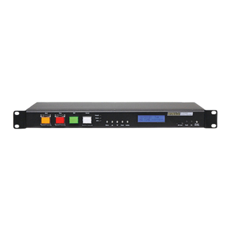
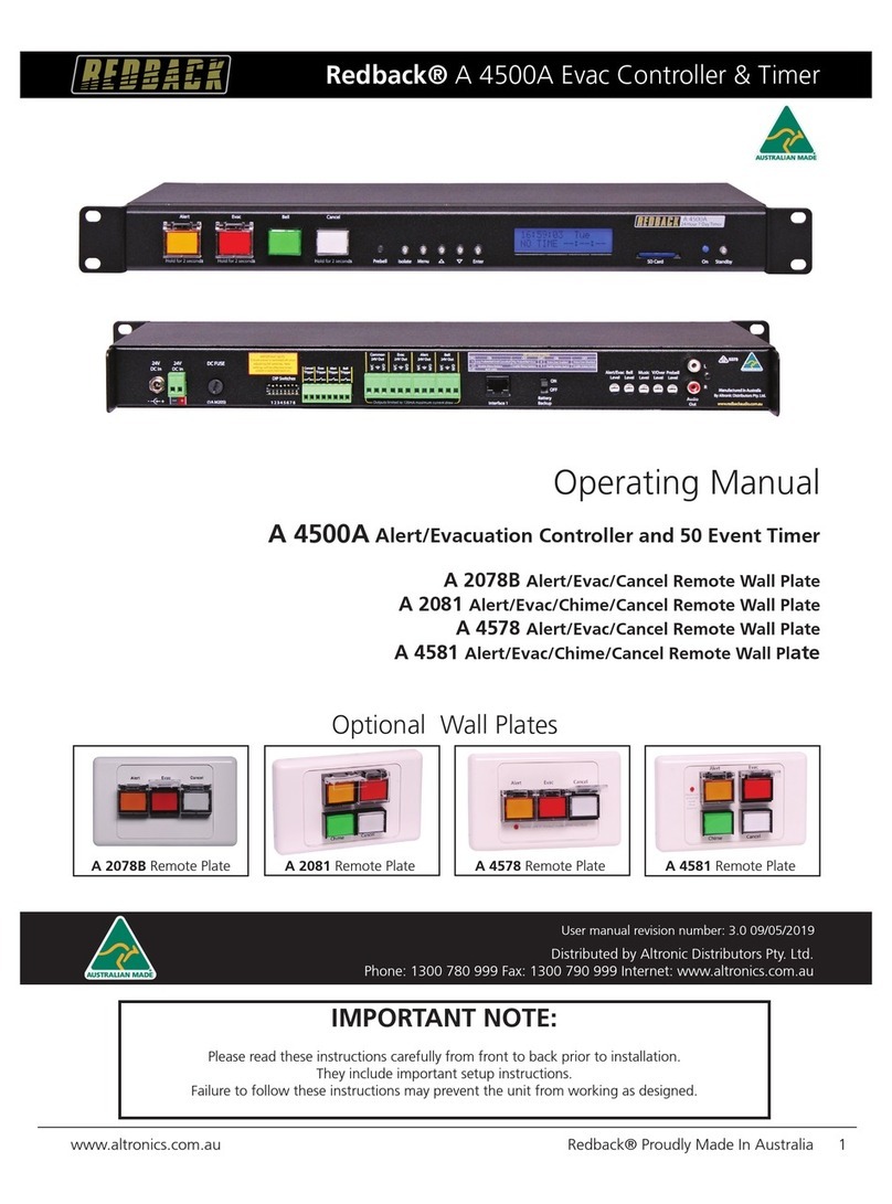
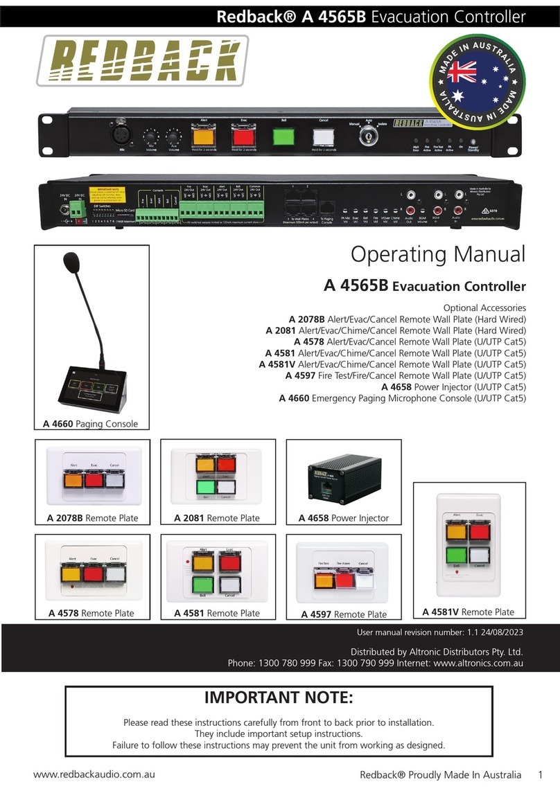
Redback A 4595A User manual

www.altronics.com.au Redback® Proudly Made In Australia 1
Redback® A 4595A School Lockdown Controller
User manual revision number: 1.0 06/05/2020
Operating Manual
A 4595A School Lockdown Controller
A 4596 Paging Console
A 4597 Fire Test Remote Wallplate
A 4598 Lockdown Remote Wallplate (Horizontal)
A 4598V Lockdown Remote Wallplate (Vertical)
Redback® Proudly Made In Australia
Distributed by Altronic Distributors Pty. Ltd.
Phone: 1300 780 999 Fax: 1300 790 999 Internet: www.altronics.com.au
IMPORTANT NOTE:
Please read these instructions carefully from front to back prior to installation.
They include important setup instructions.
Failure to follow these instructions may prevent the amplier from working as designed.
Please check www.altronics.com.au for the latest revisions of instruction manuals.
Optional Accessories
A 4596 Paging Console A 4598 Remote PlateA 4597 Remote Plate A 4598V Remote Plate

www.altronics.com.auRedback® Proudly Made In Australia2
Redback® A 4595A School Lockdown Controller
REDBACK is a registered trademark of Altronic Distributors Pty Ltd
Since 1976 Redback ampliers have been manufactured in Perth, Western Australia by Altronics. With over 44 years
experience in the commercial audio industry, we offer consultants, installers and end users reliable products of high build
quality with local product support. We believe there is signicant added value for customers when purchasing an
Australian made Redback amplier or PA product
Australian Made Status
All Redback house products made by Altronics will now be sporting the ofcial Australian Made logo. Since starting
manufacturing of commercial audio equipment in the mid 70’s we have always taken pride in producing a quality local
product.
The new adoption of the Australian Made logo will help us get the word out to local and export markets that our
products carry the ofcial compliance seal of the Australian Made campaign. We have always pushed our ‘local is better’
line in all of our marketing efforts, it’s always an added boost when you are backed up by a widely recognised and
respected icon.
Industry leading 10 year warranty.
There’s a reason we have the industry leading DECADE warranty. It’s because of a long tried and tested history of
bulletproof reliability. We’ve heard PA contractors tell us they still see the original Redford amplier still in service in schools
- that’s over 44 years of operation - and still going strong!
All Australian made Redback products are covered by a 10 year warranty.
Should a product become faulty please contact us to obtain a return authorisation number. Please ensure you have all the
relevant documentation on hand. We do not accept unauthorised returns. Proof of purchase is required so please retain
your invoice.
Published by Altronic Distributors
© 2020 Altronic Distributors

www.altronics.com.au Redback® Proudly Made In Australia 3
Redback® A 4595A School Lockdown Controller
CONTENTS
1.0 Overview
1.1 Introduction 4
1.2 Features 4
1.3 What’s in the box 4
1.4 Front panel guide 5
1.5 Rear panel connections 6
2.0 Operation
2.1 Lockdown Modes 8
2.2 Fire Test/Fire Alarm 8
2.3 Prebell/Bell 8
2.4 Auxilliary MP3 Triggers 8
2.5 Priorities 9
3.0 Setup Guide
3.1 Power Connections 9
3.2 Audio Connections 10
3.3 24V Output Connections 10
3.4 Micro SD card (MP3) 12
3.5 Connecting to the A 4565 15
3.6 Connecting to the A 4565 and the A 4585 16
3.7 Dip Switch Settings 16
4.0 Paging Consoles
4.1 A 4596 Paging Console Overview 17
4.2 A 4598 and A 4598V Overview 20
4.3 A 4597 Overview 22
5.0 Troubleshooting
5.1 Symptoms and Remedies 23
5.2 RJ45 Cabling Conguration 23
6.0 Specications 24

www.altronics.com.auRedback® Proudly Made In Australia4
Redback® A 4595A School Lockdown Controller
1.0 OVERVIEW
1.1 INTRODUCTION
This lockdown controller complements the A 4565 Alert/Evac controller and is primarily aimed at schools which require a
lockdown warning facility. The controller has provision for a Pre-Bell and a Period Bell which are activated by the closing
contact triggers on the rear of the unit. Standby, Lock In, Lock Out and All Clear tones can be activated by the switches on
the front of the controller, or by the optional wall plates (A 4598) or paging consoles (A 4596).
The unit is powered from a 24V dc source (power supply included) and separate 24V dc switched outputs are supplied
for remote triggering (of sirens/strobes etc) for all tone conditions (Bell/Pre-bell, Standby, Lock In, Lock Out and All Clear).
There is also an Emergency 24V out which is activated on Standby, Lock In, Lock Out and All Clear conditions and when
emergency paging is active. A Common 24V Out is activated by any tone condition or by any paging state. Connections to
the paging consoles and wall plates are made via Cat5e cabling.
The audio output is typical 1V rms line level and is adjustable via a trimpot adjustment on the rear of the unit.
The lockdown unit can be connected to the A 4565 alert/evac controller if an EWIS system is also required and is made
with a dual RCA lead . The A 4565 will take priority over the A 4595A lockdown unit in the case of an emergency.
1.2 FEATURES
• Standard 1U 19” rack mount case
• Front panel activation of Standby, Lock In, Lock Out and All Clear Modes
• Remote operation of Prebell & Bell tones
• Remote operation of three optional triggers
• SD card storage of audio les
• 24V DC operation
• Switched 24V DC output for Prebell, Bell, Standby, LockIn, LockOut & All Clear Triggers
• Auxiliary level output
• Suitable for any amplier with an auxiliary input
• 10 Year Warranty
• Australian Designed and Manufactured
1.3 WHAT’S IN THE BOX
A 4595A Alert/Evacuation Controller
24V 2amp Power supply
Instruction Booklet
Micro SD Card

www.altronics.com.au Redback® Proudly Made In Australia 5
Redback® A 4595A School Lockdown Controller
1.4 FRONT PANEL GUIDE
Fig 1.4A shows the layout of the A 4595A front panel.
Fig 1.4A
1 Standby Tone Activation Switch
This switch is used to activate the Standby Mode.
2 Lock In Tone Activation Switch
This switch is used to activate the Lock In Mode.
3 Lock Out Tone Activation Switch
This switch is used to activate the Lock Out Mode.
4 All Clear Tone/Cancel Activation Switch
This switch is used to activate the All Clear Mode and to cancel any currently playing tone.
5 PA Active Indicator
This led will illuminate when the A 4596 paging microphone is active.
6 Emergency Paging Active Indicator
This led will illuminate when the Emergency paging on the A 4596 paging microphone is active.
7 Bell/Pre Bell Indicator
This led indicates that the Bell or Pre-Bell has been activated.
8 MP3 Error Indicator
This led indicates that an error has occurred with the internal MP3 player.
9 On Indicator
This led indicates the unit has power.
10 Power/Standby Switch
When the unit is in standby mode this switch will illuminate. Press this button to switch the unit ON. Once the
unit is ON the On indicator will illuminate. Press this switch again to put the unit back in standby mode.
Power/
Lock In
Standby Lock Out All Clear/Cancel
Lockdown Controller
A 4595A
Press for ALL CLEAR
Press and hold to CANCEL
On
PA
Active
Bell/
Pre-Bell
Active
Emergency
Paging
Active
Mp3
Error Standby
1 2 348910
67
5

www.altronics.com.auRedback® Proudly Made In Australia6
Redback® A 4595A School Lockdown Controller
1.5 REAR PANEL CONNECTIONS
Fig 1.5A shows the layout of the A 4595A rear panel.
Fig 1.5A
1 All Clear 24V Out
This is a 24V DC output which is activated when the All Clear Mode is triggered. The terminals provided can be
used for “Normal” or “Failsafe” modes (see section 3.5 for more details).
2 Lock In 24V Out
This is a 24V DC output which is activated when the Lock In Mode is triggered. The terminals provided can be
used for “Normal” or “Failsafe” modes (see section 3.5 for more details).
3 Standby 24V Out
This is a 24V DC output which is activated when the Standby Mode is triggered. The terminals provided can be
used for “Normal” or “Failsafe” modes (see section 3.5 for more details).
4 Lock Out 24V Out
This is a 24V DC output which is activated when the Lock Out Mode is triggered. The terminals provided can be
used for “Normal” or “Failsafe” modes (see section 3.5 for more details).
5 Bell/Pre-Bell 24V Out
This is a 24V DC output which is activated when the Bell or Pre-Bell tone is triggered. The terminals provided can
be used for “Normal” or “Failsafe” modes (see section 3.5 for more details).
6 Common 24V Out
This is a combined 24V DC output which is activated when any of the Bell, Pre-Bell, Standby, Lock In, Lock Out,
All Clear, Aux MP3-1, Aux MP3-2 or Aux MP3-3 tones are activated or when paging is active. The terminals
provided can be used for “Normal” or “Failsafe” modes (see section3.5 for more details).
7 Emergency 24V Out
This is a 24V DC output which is activated when the Standby, Lock In, Lock Out and All Clear tones are activated
or when Emergency paging is active. The terminals provided can be used for “Normal” or “Failsafe” modes (see
section 3.5 for more details).
8 RJ45 connectors for Wall Plates
These RJ45 ports connect to the wall plates. A Maximum of 16 plates is recommended, (If more than 16 wall
plates are required contact Altronics for conguration details).
9 RJ45 connectors for Paging Consoles
These RJ45 ports connect to the paging consoles. A Maximum of 4 paging consoles is recommended.
10 MP3 Volume
Adjust this trimpot to adjust the MP3 tones volume.
11 Master Volume
Adjust this trimpot to adjust the master volume.
1 2 3 4 5 6 7 8 9 10 11 12
1314
15
16
20
21
22
23 17
18
19
+_
DIP Switch Settings
SW
1
2-8
On O
Loop MP3
Not Used
Play MP3 once
+_
24V DC
IN
L
R
Audio
Out
Master
Volume
Aux MP3-3
DIP Switches
Interface 1
All Clear
24V Out
Lock Out
24V Out
Lock In
24V Out
Standby
24V Out
Interface 2
IMPORTANT NOTE
Ensure power is switched o when
adjusting DIP switches. New
settings will be eective when
power is switched back on.
24V DC
IN
(16GB Maximum)
Mp3
Volume
Micro SD Card
1 2 3 4 5 6 7 8 To Wall Plates
+
-
Bell/Pre-Bell
24V Out
Common
24V Out
Emergency
24V Out
All switched outputs limited to 120mA maximum current draw
To Paging Consoles
Contacts
Aux MP3- 2
Aux MP3-1
Bell
Pre-Bell
34
12
(Maximum 500mA per output)
34
12
Made in Australia by
Altronic Distributors
Pty Ltd
www.redbackaudio.com.au
N/O
N/C
N/O
N/C
N/O
N/C
N/O
N/C
N/O
N/C
N/O
N/C
N/O
N/C
1 2 3 4 5 6 7 8

www.altronics.com.au Redback® Proudly Made In Australia 7
Redback® A 4595A School Lockdown Controller
12 Audio Out RCA Connectors
Connect these outputs to the input of the PA amplier.
13 RJ45 connector
This RJ45 ports is for future peripheral devices.
14 RJ45 connector
This RJ45 ports is for future peripheral devices.
15 Pre-Bell Contact
These contacts are for remote triggering of the Pre-Bell tone. This is the tone usually played before the main
school Bell.
16 Bell Contact
These contacts are for remote triggering of the Bell tone. This is the tone usually played for the school Bell.
17 Aux MP3-1 Contact
These contacts are for remote triggering of custom tone 1. There are three contacts for user custom tones.
18 Aux MP3-2 Contact
These contacts are for remote triggering of custom tone 2. There are three contacts for user custom tones.
19 Aux MP3-3 Contact
These contacts are for remote triggering of custom tone 3. There are three contacts for user custom tones.
20 Micro SD Card Socket
This socket holds the Micro SD card which is used to store all the tones or audio MP3 les.
21 Dip Switches
These are used to select various options. (see section 3.6 for more details).
22 24V DC Input (Backup)
Connects to a 24V DC backup supply with at least 1.5 amp current capacity. (Please observe the polarity)
23 24V DC Input (Main Supply)
Connects to a 24V DC supply with at least 1.5 amp current capacity. (Please observe the polarity)

www.altronics.com.auRedback® Proudly Made In Australia8
Redback® A 4595A School Lockdown Controller
2.0 OPERATION
2.1 LOCKDOWN MODES
The A 4595A Lockdown controller has four Lockdown Modes which are Standby, Lock In, Lock Out and All Clear.
Once a Lockdown mode is activated an MP3 audio le is played until the audio le nishes or the A 4595A changes mode.
The Audio Files can be an Alert or Evac tone, a piece of music or a recorded message, etc and are stored on the internal
SD Card (supplied). Audio les will be supplied to provide basic functionality but the installer will be required to copy their
own audio les onto the SD Card (See section 3.6 for more details).
• Standby Mode - This would typically be used to notify students and staff that there may be a possible situation in
the school grounds and to “Standby” for a possible Lock Down.
A music track which doesn’t cause panic but is known by the staff would be an appropriate
audio le to be played in this mode.
• Lock In Mode - This mode would be used to notify students and staff that there is a situation outside the school
class rooms but still in the school grounds (eg The School Oval) or maybe the hall ways.
Students and staff would be then required to lock themselves inside their class rooms.
A warning tone, maybe with a repeating message may be suitable.
• Lock Out Mode - This mode would be used to notify students and staff that there is a situation inside the school
buildings. Students and staff would be then required to remain outside their class rooms or
other school buildings, but remain in the school grounds. This may be applicable when students
are on a lunch break and are playing outside.
A warning tone, maybe with a repeating message may be suitable.
• All Clear Mode - This would notify students and staff that it is now safe and that the situation has been rectied.
A music track which is known by the staff would be an appropriate audio le to be played in this
mode.
The lockdown modes can be activated in a number of ways.
1) Pressing the buttons on the front of the A 4595A.
2) Activating the modes by the A 4598 optional remote plates (see section 4.3).
3) Activating the modes via the A 4596 optional paging microphones (see section 4.2).
2.2 FIRE TEST/FIRE ALARM
The A 4595A has two Fire Modes (Fire Test and Fire Alarm) which can only be triggered via the optional A 4597 Wall Plate.
Once a Fire mode is activated an MP3 audio le is played until the audio le nishes or the A 4595A changes mode.
The Audio Files can be an alarm tone, a piece of music or a recorded message, etc and are stored on the internal Micro
SD Card (supplied). Audio les will be supplied to provide basic functionality but the installer will be required to copy their
own audio les onto the Micro SD Card (See section 3.6 for more details).
2.3 PREBELL/BELL
As the A 4595A is aimed primarily at schools, a Prebell and Bell function have been included. These are triggered by
closing contact terminals on the rear of the unit and could be triggered by a timer such as the Altronics A 1709 Timer as
shown in gure 3.3. Once the Prebell or Bell mode is activated an MP3 audio le is played until the audio le nishes or
the A 4595A changes mode. (See section 3.4 for more details)
An indicator on the front of the unit will illuminate when the Prebell or Bell tone is active.
2.4 AUXILLIARY MP3 TRIGGERS
There may be times when extra tones or audio les are required to be played through the A 4595A. Examples might
include playing a message each week calling students to assembly. These are triggered by closing contact terminals on the
rear of the unit. Once the Aux MP3’s are activated an MP3 audio le is played until the audio le nishes or the A 4595A
changes mode. (See section 3.4 for more details)
An indicator on the front of the unit will illuminate when any of the Aux MP3 tones is active.

www.altronics.com.au Redback® Proudly Made In Australia 9
Redback® A 4595A School Lockdown Controller
2.5 PRIORITIES
The order of priority for the functions of the A 4595A are as follows.
1) Emergency paging (Via the optional A 4596 paging consoles)
2) Fire Alarm (Via optional A 4597 wall plate)
3) All Clear Mode, LockIn or Lockout Mode
4) Standby Mode
5) General paging (Via the optional A 4596 paging consoles)
6) Fire Test (via optional A 4597 wall plate), PreBell/Bell, AuxMP3-1, AuxMP3-2, AuxMP3-3
■Emergency Paging
Emergency paging via the optional A 4596 paging console, overrides all other functions of the A 4595A. If
emergency paging is activated by pressing the Emergency paging button on the paging console, and any of the
Standby, Lock In, Lock Out or All Clear modes (the four Lock Down modes) are triggered these will become active
once the emergency paging nishes.
If any of the Lock Down modes are already active and paging is initiated, it will override these modes, returning to
them once paging has nished. Note: To activate emergency paging while the unit is in any of the Lock down
modes, the emergency paging button doesn’t need to be pressed. It is simply a matter of using the paging toggle
switch to page.
■ Fire Alarm
This has the highest priority of all modes and can only be overridden by emergency paging.
The Fire Alarm can only be initiated by the Fire Alarm wall plate (A 4597).
■All Clear Mode ,Lock In or Lock Out Mode
The All Clear, Lock In and Lock Out modes all have the same priority, meaning that if one mode is active and the
other mode is triggered, the unit will switch over to the other mode. All three of these modes can be overridden
by emergency paging.
■Standby Mode
The standby mode has the lowest priority of the four Lock Down Modes but will override the Fire Test, Prebell/Bell
or the Aux MP3 tones.
■General Paging
General paging via the optional A 4596 paging console overrides the Fire Test, PreBell, Bell and AuxMP3-1 to Aux
MP3-3 triggers.
■Fire Test, PreBell/Bell Tone ,AuxMP3-1, AuxMP3-2, AuxMP3-3
These triggers have the lowest priority of all functons on the A 4595A are can be overridden by every other
function.
The Fire test can only be initiated by the Fire Test wall plate (A 4597).
3.0 SETUP GUIDE
3.1 POWER CONNECTIONS
A DC socket and a 2 way terminal have been provided for 24V DC input.
The DC socket is for connection of the supplied plugpack which comes with a standard 2.1mm jack connector.
The 2 way terminal is for connection of a backup power supply or battery.

www.altronics.com.auRedback® Proudly Made In Australia10
Redback® A 4595A School Lockdown Controller
3.2 AUDIO CONNECTIONS
Audio Output:
This output consists of stereo RCA sockets with an output of 0dBm into a 600Ω input. This is suitable for most PA
amplier auxiliary inputs. The output level is adjusted via the Master volume trimpot on the rear of the unit. The output
level of the MP3 audio les is adjusted via the MP3 level trimpot on the rear of the unit.
Fig 3.2
3.3 24V DC OUTPUT CONNECTIONS
There are seven sets of output terminals for the connection of 24V DC driven devices. E.g School Bell, warning strobes,
override relays in volume controls etc.
Each set of output terminals have a N/O (normally open), N/C (normally closed) and a ground connection. In this
conguration 24V appears between the N/O and ground terminals when this output is activated. When this output is not
active 24V appears between the N/C and ground terminals.
(NOTE: The maximum current draw per output is about 120 milliamps, so it is advisable to run external 24V DC relays
instead of trying to drive a 24V DC device directly from these outputs. See Fig 3.3 for an example of this).
Bell/Pre Bell 24V Out:
These contacts are for operating an external relay used to operate something like a school bell.
Fig 3.3 demonstrates an example of how to connect the A 4595A Lockdown Controller to the Altronics A 1708 timer to
trigger the schools Pre-Bell and Bell .
The Zone 1 closing contact of the timer is used to trigger the school Pre-bell contact and the Zone 2 closing contact is
used to trigger the school Bell. In the example shown the Bell/Pre Bell 24V Output is used to drive a 24V school Bell.
As the current draw of the Bell is more than 120mA a relay board is used to switch an external power supply. The
Altronics S 4444 24V Relay Board as shown below or the S 4455 12/24/48V Din Rail Relay box are inexpensive and easily
installed options designed for this purpose.
Standby 24V Out:
These contacts are for switched 24V outputs whenever the Standby mode is activated. These may be used to run
external systems such as strobes in unusually noisy environments or for hearing impaired students or staff. They may also
be used for the connection of override relays in remote volume controls. An override relay is necessary where
attenuators are used so that the audio is broadcast at full volume regardless of the volume setting on the individual vol-
ume control (attenuator).
A 4595A LOCKDOWN CONTROLLER
4 -16Ω70V100V OUTPUTS L
R
24V DC IN
Balanced Mic
+_
PTT
(short to
activate)
Power Fail
(Contacts
close on
power fail)
SendReturn
Tape Out
Preamp Out
Link To Charge
Backup battery
Input 1Input 3 Input 2Input 4Input 5Input 6
ALERT - EVAC MODULE
Output Levels
Voice Chime Alert
Over & Evac EV COMCANCH
AL
Triggers
L
R
+
–
Rem. Vol
Connect
to 1KΩPot
+
–
+
–
+
–
Line
24V DC
Switched
Output
DIP 5
Interface
DIP 4
DIP 1
DIP 2DIP 3
Balanced Mic
Line
Balanced Mic
Line
Balanced Mic
Line
Balanced Mic
Line
Balanced Mic
Line
Balanced Line
L
R
L
R
L
R
L
R
L
R
2 1
3
2 1
3
2 1
3
2 1
3
2 1
3
2 1
3
2 1
3
1 2 3 4 5 6 7 8
1 2 3 4 1 2 3 4 1 2 3 4 1 2 3 4
230V AC @ 50Hz
www.altronics.com.au
RESETTABLE
DC FUSE
Made in Australia
by Altronic
Distributors
Pty Ltd
DIP 5
DIP 4
IMPORTANT NOTE
Ensure power is switched OFF when
adjusting DIP switches. New
settings will be eective when
power is switched back on.
DIP 3
SW Item On O
1
2
Input 6 Level 1V 100mV
3
Not USed
4Input 5 Level 1V 100mV
Not USed
1
2
3
4
DIP 2
SW Item On O
Input 4 Level 1V 100mV
Not USed
Input 3 Level 1V 100mV
Input 3 Priority On O
*
DIP 1
SW Item On O
1
2
Input 2 Level 1V 100mV
3
Input 2 Priority On O
4Input 1 Level 1V 100mV
Input 1 Priority On O
*
*
SW Item On O
1
2
3
4Not Used
Not Used
Not Used
Not Used
DIP 4
DIP 1
DIP 2DIP 3
SW Item On O
Switched 24VDCOutOn O
Phantom Power Input 6 On O
On O
1
2
3
4Phantom Power Input 5
On O
5Phantom Power Input 4
On O
6Phantom Power Input 3
On O
7Phantom Power Input 2
On O
8Phantom Power Input 1
Preamp Out †Post
Pre
†Sets the Preamplier output to
Pre or Post Master.
DIP 5
Priority or VOX muting is only
functional on inputs 1-3. When
VOX is enabled on input 1 it will
override all other inputs includ-
ing the Alert/Evac Module. VOX
enabled on input 2 will override
inputs 3-6. VOX enabled on input
3 will override inputs 4-6.
If the Alert/Evac module is tted
it will override inputs 2-6.
*
Model 125W
5AAC Fuse
250W
7.5A
AC Fuse Ratings
RISK OF ELECTRIC SHOCK
OPEN BY QUALIFIED
PERSONNEL ONLY !
CAUTION
PA AMPLIFIER
Output volume set by
master volume.
MP3 audio le output
set by MP3 volume.
DIP Switch Settings
SW
1
2-8
On O
Loop MP3
Not Used
Play MP3 once
+_
24V DC
IN
L
R
Audio
Out
Master
Volume
Aux MP3-3
DIP Switches
Interface 1
All Clear
24V Out
Lock Out
24V Out
Lock In
24V Out
Standby
24V Out
Interface 2
IMPORTANT NOTE
Ensure power is switched o when
adjusting DIP switches. New
settings will be eective when
power is switched back on.
24V DC
IN
(16GB Maximum)
Mp3
Volume
Micro SD Card
1 2 3 4 5 6 7 8 To Wall Plates
+-
Bell/Pre-Bell
24V Out
Common
24V Out
Emergency
24V Out
All switched outputs limited to 120mA maximum current draw To Paging Consoles
Contacts
Aux MP3- 2
Aux MP3-1
Bell
Pre-Bell
34
12
(Maximum 500mA per output)
34
12
Made in Australia by
Altronic Distributors
Pty Ltd
www.redbackaudio.com.au
N/O
N/C
N/O
N/C
N/O
N/C
N/O
N/C
N/O
N/C
N/O
N/C
N/O
N/C
1 2 3 4 5 6 7 8

www.altronics.com.au Redback® Proudly Made In Australia 11
Redback® A 4595A School Lockdown Controller
Lock In 24V Out:
These contacts are for switched 24V outputs whenever the LockIn mode is activated. These may be used to run external
systems such as strobes in unusually noisy environments or for hearing impaired students or staff. They may also be used
for the connection of override relays in remote volume controls.
Lock Out 24V Out:
These contacts are for switched 24V outputs whenever the LockIn mode is activated. These may be used to run external
systems such as strobes in unusually noisy environments or for hearing impaired students or staff. They may also be used
for the connection of override relays in remote volume controls.
All Clear 24V Out:
These contacts are for switched 24V outputs whenever the All Clear mode is activated. These may be used to run external
systems such as strobes in unusually noisy environments or for hearing impaired students or staff. They may also be used
for the connection of override relays in remote volume controls.
Common 24V Out:
These contacts are for switched 24V outputs whenever any Bell, Pre-Bell, Standby, Lock In, Lock Out, All Clear, Fire Test,
Aux MP3-1, Aux MP3-2 or Aux MP3-3 tones are activated or when paging is active. These may be used to run external
systems such as strobes in unusually noisy environments or for hearing impaired students or staff. They may also be used
for the connection of override relays in remote volume controls.
Emergency 24V Out:
These contacts are for switched 24V outputs whenever the Standby, Lock In, Lock Out, Fire Test, Fire Alarm and All Clear
modes are activated or when emergency paging is active. These may be used to run external systems such as strobes in
unusually noisy
environments or for hearing impaired students or staff. They may also be used for the connection of override relays in
remote volume controls.
A possible use for this output would be to override the zone which provides audio to the school assembly area. General
paging is blocked to this area but emergency paging is still required.
Fig 3.3
DIP Switch Settings
SW
1
2-8
On O
Loop MP3
Not Used
Play MP3 once
+_
24V DC
IN
L
R
Audio
Out
Master
Volume
Aux MP3-3
DIP Switches
Interface 1
All Clear
24V Out
Lock Out
24V Out
Lock In
24V Out
Standby
24V Out
Interface 2
IMPORTANT NOTE
Ensure power is switched o when
adjusting DIP switches. New
settings will be eective when
power is switched back on.
24V DC
IN
(16GB Maximum)
Mp3
Volume
Micro SD Card
1 2 3 4 5 6 7 8 To Wall Plates
+
-
Bell/Pre-Bell
24V Out
Common
24V Out
Emergency
24V Out
All switched outputs limited to 120mA maximum current draw
To Paging Consoles
Contacts
Aux MP3- 2
Aux MP3-1
Bell
Pre-Bell
34
12
(Maximum 500mA per output)
34
12
Made in Australia by
Altronic Distributors
Pty Ltd
www.redbackaudio.com.au
N/O
N/C
N/O
N/C
N/O
N/C
N/O
N/C
N/O
N/C
N/O
N/C
N/O
N/C
1 2 3 4 5 6 7 8
24V Bell
(eg school bell, lunch bell etc)
+24V
GND
24V Relay Board
(Altronics S 4444)
N/C1
N/C2
N/O2
N/O1
COM1
COM2
External
24V DC Supply
+24V
GND
24V DC Switched Out
(Outputs limited to 120mA)
SD Card
Micro
(Firmware
updates)
24VDC
Input
24VDC
Backup
4 3 2 1
4 3 2 1
Manufactured in Australia
By Altronic Distributors Pty. Ltd.
DIP Switches
Interface
++
__
++
__
+-
1 2 3 4 5 6 7 8
DIP Switch Settings
SW ON
1
2
Station Edit Lockout Enabled
3
Edit Time Lockout Enabled
4
Clear Memory Lockout Enabled
Not Used
Battery Backup On
Not Used
5-7
8
+_
A 1709
50 EVENT TIMER

www.altronics.com.auRedback® Proudly Made In Australia12
Redback® A 4595A School Lockdown Controller
3.4 Micro SD CARD (MP3)
The micro SD card supplied with the unit has audio les for testing purposes only. These audio les do not meet any Aus-
tralian standards or fulll any particular criteria.
The audio les must be in MP3 format (they cannot be WMA) and are stored in folders on the Micro SD Card.
NOTE: It is recommended to store only one MP3 le in each folder.
The A 4595A will play the rst le it nds in each folder which corresponds to the mode the unit is running in.
For example if “Standby Mode” is activated, the A 4595A will search the “Standby” folder on the Micro SD card, and
then play the corresponding MP3 le. If DIP switch 1 is set to “ON” (See DIP switch settings in section 3.6) the MP3 will be
played in a continuous loop. If DIP Switch 1 is set to “OFF” the MP3 will play only once.
The length of time the MP3 plays for is determined by the length of the actual MP3 le itself.
3.6.1 Installing MP3’s on to the A 4595A
• Firstly remove power from the A 4595A and then remove the Micro SD card from the rear of the unit.
To remove the Micro SD card, push the card in and it will eject itself.
The Micro SD card will then need to be connected to a PC, equipped with a Micro SD card reader.
• Make sure the PC is ON and the card reader is connected and correctly installed. Then insert the Micro SD card into the
reader.
• Go to “My computer” as shown in Fig 3.4a and open the Micro SD card which may be labelled Local Disk or Removable
Disk.
Fig 3.4a
• Once the Micro SD card has been opened you should see a series of folders as shown in Fig 3.4b. These folders relate to
the triggers and modes of the A 4595A. E.g the “All Clear” folder contains the MP3 which is played when the “All Clear”
mode is activated.
NOTE: There is a folder labelled #LIBRARY# which has some samples tones, school bells etc.
NOTE: Some A 4595A models may not have the Fire and Firetest folders supplied on the SD card. If using the A
4597 wall plate (See section 4.3), these folders will need to be added to the SD card.
We will use the allclear folder to demonstrate the installation of the MP3 le.
Open Local Disk or
Removable Disk

www.altronics.com.au Redback® Proudly Made In Australia 13
Redback® A 4595A School Lockdown Controller
Fig 3.4b
• Open the allclear folder and inside you should nd an MP3 audio le as shown in Fig 3.4c. Delete this le and copy your
own MP3 le to this folder as shown in g 3.4d (NOTE : The audio le must be in MP3 format). The le can be named
anything you like as long as it is in MP3 format (iin this case we have named it New_allclear_tone).
(NOTE : Do not rename any of the folders.)
Fig 3.4c
Fig 3.4d
Your custom
MP3 le.
Delete this le
and replace it
with a new MP3
all clear folder

www.altronics.com.auRedback® Proudly Made In Australia14
Redback® A 4595A School Lockdown Controller
• The new MP3 le you have installed cannot be “Read Only”.
To check if the le is read-only, select the properties of the le (as shown in Fig 3.4e) by either
a) right clicking on the le with your mouse and then selecting “Properties”of the le.
b) selecting “File” in the tabs bar and then selecting “Properties”of the le.
Fig 3.4e
• The properties will then come up as shown in Fig 3.4f. Make sure the Read-only check box is not checked.
Fig 3.4f
• The “All Clear” MP3 le is now installed and ready to function as it should. Repeat this procedure for all the MP3 les
required. Once complete, remove the SD card from the PC, following Windows safe card removal procedures.
Make sure the A 4595A is OFF and then insert the SD card back into the rear of the unit. The SD card holder will click
when the SD card is inserted correctly.
Select the
Properties option
Make sure the
Read-only box is
not checked.

www.altronics.com.au Redback® Proudly Made In Australia 15
Redback® A 4595A School Lockdown Controller
3.5 CONNECTING TO THE A 4565 ALERT/EVAC CONTROLLER
A complete Fire Evacuation System can be congured when the A 4595A is complemented with the A 4565
Alert/Evacuation Controller.
The A 4565 controller is designed around industry standard building emergency alert/evacuate requirements. When con-
nected to a paging system amplier, building occupants can be alerted and/or evacuated in the event of an emergency
e.g.: re, gas leak, bomb scare, earthquake.
The output of the A 4595A Lockdown controller is connected to the Audio In Input of the A 4565 using dual RCA leads.
The output volume is set by the Master volume trimpot adjustment on the rear of the A 4595A. The output of the A 4565
is then fed into the buildings PA system.
When connected in this manner the A 4565 Alert/Evac Controller has priority over the entire system and once any
function on the A 4565 has been activated it will override any mode the A 4595A Lockdown Controller may be in.
Fig 3.5
A 4595A LOCKDOWN CONTROLLER
A 4565 ALERT/EVAC CONTROLLER
4 -16Ω70V100V OUTPUTS L
R
24V DC IN
Balanced Mic
+_
PTT
(short to
activate)
Power Fail
(Contacts
close on
power fail)
SendReturn
Tape Out
Preamp Out
Link To Charge
Backup battery
Input 1Input 3 Input 2Input 4Input 5Input 6
ALERT - EVAC MODULE
Output Levels
Voice Chime Alert
Over & Evac EV COMCANCH
AL
Triggers
L
R
+
–
Rem. Vol
Connect
to 1KΩPot
+
–
+
–
+
–
Line
24V DC
Switched
Output
DIP 5
Interface
DIP 4
DIP 1
DIP 2DIP 3
Balanced Mic
Line
Balanced Mic
Line
Balanced Mic
Line
Balanced Mic
Line
Balanced Mic
Line
Balanced Line
L
R
L
R
L
R
L
R
L
R
2 1
3
2 1
3
2 1
3
2 1
3
2 1
3
2 1
3
2 1
3
1 2 3 4 5 6 7 8
1 2 3 4 1 2 3 4 1 2 3 4 1 2 3 4
230V AC @ 50Hz
www.altronics.com.au
RESETTABLE
DC FUSE
Made in Australia
by Altronic
Distributors
Pty Ltd
DIP 5
DIP 4
IMPORTANT NOTE
Ensure power is switched OFF when
adjusting DIP switches. New
settings will be eective when
power is switched back on.
DIP 3
SW Item On O
1
2
Input 6 Level 1V 100mV
3
Not USed
4Input 5 Level 1V 100mV
Not USed
1
2
3
4
DIP 2
SW Item On O
Input 4 Level 1V 100mV
Not USed
Input 3 Level 1V 100mV
Input 3 Priority On O
*
DIP 1
SW Item On O
1
2
Input 2 Level 1V 100mV
3
Input 2 Priority On O
4Input 1 Level 1V 100mV
Input 1 Priority On O
*
*
SW Item On O
1
2
3
4Not Used
Not Used
Not Used
Not Used
DIP 4
DIP 1
DIP 2DIP 3
SW Item On O
Switched 24VDCOutOn O
Phantom Power Input 6 On O
On O
1
2
3
4Phantom Power Input 5
On O
5Phantom Power Input 4
On O
6Phantom Power Input 3
On O
7Phantom Power Input 2
On O
8Phantom Power Input 1
Preamp Out †Post
Pre
†Sets the Preamplier output to
Pre or Post Master.
DIP 5
Priority or VOX muting is only
functional on inputs 1-3. When
VOX is enabled on input 1 it will
override all other inputs includ-
ing the Alert/Evac Module. VOX
enabled on input 2 will override
inputs 3-6. VOX enabled on input
3 will override inputs 4-6.
If the Alert/Evac module is tted
it will override inputs 2-6.
*
Model 125W
5AAC Fuse
250W
7.5A
AC Fuse Ratings
RISK OF ELECTRIC SHOCK
OPEN BY QUALIFIED
PERSONNEL ONLY !
CAUTION
PA AMPLIFIER
DC FUSE
24V DC
IN
1 2 3 4 5 6 7 8
+_
DC FUSE
(2A M205)
L
R
Audio
In
Chime
Vol
Fire
DIP Switches
Interface
Alert
24V Out
Fire
24V Out
Evac
24V Out
To Paging
Console
IMPORTANT NOTE
Ensure power is switched o when
adjusting DIP switches. New
settings will be eective when
power is switched back on.
24V DC
IN
(16GB Maximum)
V/Over
Vol
SD Card 1 2 3 4 5 6 7 8 To Wall Plates
+
-
Bell
24V Out
Common
24V Out
All switched outputs limited to 120mA maximum current draw
Contacts
Evac
Alert
Bell
Cancel
34
(Maximum 500mA per output)
Made in Australia by
Altronic Distributors
Pty Ltd
www.redbackaudio.com.au
L
R
L
R
BGM
Volume
Audio
Out
BGM
In
Fire
Vol
Bell
Vol
Evac
Vol
PA Mic
Vol
N/C
N/O
N/C
N/O
N/C
N/O
N/C
N/O
N/C
N/O
12
DIP Switch Settings
SW
1
2-8
On O
Loop MP3
Not Used
Play MP3 once
+_
24V DC
IN
L
R
Audio
Out
Master
Volume
Aux MP3-3
DIP Switches
Interface 1
All Clear
24V Out
Lock Out
24V Out
Lock In
24V Out
Standby
24V Out
Interface 2
IMPORTANT NOTE
Ensure power is switched o when
adjusting DIP switches. New
settings will be eective when
power is switched back on.
24V DC
IN
(16GB Maximum)
Mp3
Volume
Micro SD Card
1 2 3 4 5 6 7 8 To Wall Plates
+
-
Bell/Pre-Bell
24V Out
Common
24V Out
Emergency
24V Out
All switched outputs limited to 120mA maximum current draw
To Paging Consoles
Contacts
Aux MP3- 2
Aux MP3-1
Bell
Pre-Bell
34
12
(Maximum 500mA per output)
34
12
Made in Australia by
Altronic Distributors
Pty Ltd
www.redbackaudio.com.au
N/O
N/C
N/O
N/C
N/O
N/C
N/O
N/C
N/O
N/C
N/O
N/C
N/O
N/C
1 2 3 4 5 6 7 8
Output volume set by
master volume.

www.altronics.com.auRedback® Proudly Made In Australia16
Redback® A 4595A School Lockdown Controller
3.6 CONNECTING THE LOCKDOWN CONTROLLER TO THE A 4565 ALERT/EVAC CONTROLLER
AND THE A 4580 16 ZONE PAGING SYSTEM.
A complete Fire Evacuation and paging system can be congured when the A 4595A is connected to the A 4565
Alert/Evacuation Controller and the A 4580 16 Zone Paging System.
In order to allow the A 4595A and the A 4565 to be fed through the paging system, the wiring diagram shown in Fig 3.6
must be followed. The audio output of the A 4595A is fed into the BGM (background music input) of the A 4565. The
Audio output of the A 4565 is then fed into the Evac input of the A 4580. If background music is required this is fed into
the BGM input of the A 4580, not the A 4565.
The A 4565 has the highest priority in this setup and will override any lockdown condition.
Fig 3.6
3.7 DIP SWITCH SETTINGS
IMPORTANT NOTE:
Ensure power is switched off when adjusting DIP switches.
New settings will be effective when power is switched back on.
Switch 1
This switch determines the MP3 play mode.
When set to “ON” the triggered MP3 audio le will play in a continuous loop.
When set to “OFF” the triggered MP3 audio le will play only once.
Switch 2-8 Not Used.
A 4595A LOCKDOWN CONTROLLER
A 4580 COMMUNICATOR
The Evac Input VOX sensitivity
is set by the “EVAC VOX” trimpot
on the front of the A 4580.
When using the A 4595A
Lockdown Controller, the
A 4565 Alert/Evac
Controller and the A 4580
16 Zone Communicator
together in a system, the
following wiring diagram
must be followed.
The A 4565 has the
highest priority in this
system and will over-ride
any lockdown condition.
Connections:
The Audio output from
the A 4595A Lockdown
controller is fed into the
BGM (Background Music)
input on the rear of the
A 4565 Evac Controller.
The Audio output from
the A 4565 is then fed
into the Evac input of the
A 4580 paging system.
If background music is
required through the
system it is connected to
the BGM input on the
rear of the A 4580 (Not
the A 4565).
BGM Input Level
set by the BGM
Volume trimpot.
Manufactured in Australia By Altronic Distributors Pty. Ltd.
From
BGM
AMP
L
R
BGM Out
24V
Switched
Out
From
24V
BATTERY
24V DC
IN
Zone 17-32
From
PA
AMP
Zones
1 2 3 4 5 6 7 8
1/17
34
12
+ -
+ -
2/183/194/205/216/227/238/249/2510/2611/2712/2813/2914/3015/31
16/32
100V Switching -
1 AMP SYSTEM - Connect PAamp 100V output to “From PAAMP ”Terminals
2 AMP SYSTEM - Connect PAamp 100V output to “From PAAMP ”terminals and BGM amp 100V ouput to “From BGM AMP terminals.
Connect Zone amplier speakers to ”+”and “-” terminals.
Connect Zone amplier line level inputs to“+” , ” - ” and“ ” terminals.
Preamp Switching -
DIP Switch Settings
SW
1
2
4-8
On O
Single Amp Mode
Not Used
Dual Amp Mode
Line Level Speaker Level
N/O
N/C
+-
www.redbackaudio.com.au
+_
PA Out
BGM Input Evac Input
+_
+_
324V Out Trigger
ON-Evac/OFF-Any
L
R
Extender
16GB
Maximum
Micro
SD Card
+
-
Evac
Trigger
120mA
Max
To Paging Consoles
(Maximum 500mA per output)
+- +- +- +- +- +- +- +- +- +- +- +- +- +- +-
1 2 3 4 5 6 7 8
A 4565 ALERT/EVAC CONTROLLER
DC FUSE
24V DC
IN
1 2 3 4 5 6 7 8
+_
DC FUSE
(2A M205)
L
R
Audio
In
Chime
Vol
Fire
DIP Switches
Interface
Alert
24V Out
Fire
24V Out
Evac
24V Out
To Paging
Console
IMPORTANT NOTE
Ensure power is switched o when
adjusting DIP switches. New
settings will be eective when
power is switched back on.
24V DC
IN
(16GB Maximum)
V/Over
Vol
SD Card 1 2 3 4 5 6 7 8 To Wall Plates
+-
Bell
24V Out
Common
24V Out
All switched outputs limited to 120mA maximum current draw
Contacts
Evac
Alert
Bell
Cancel
34
(Maximum 500mA per output)
Made in Australia by
Altronic Distributors
Pty Ltd
www.redbackaudio.com.au
L
R
L
R
BGM
Volume
Audio
Out
BGM
In
Fire
Vol
Bell
Vol
Evac
Vol
PA Mic
Vol
N/C
N/O
N/C
N/O
N/C
N/O
N/C
N/O
N/C
N/O
12
DIP Switch Settings
SW
1
2-8
On O
Loop MP3
Not Used
Play MP3 once
+_
24V DC
IN
L
R
Audio
Out
Master
Volume
Aux MP3-3
DIP Switches
Interface 1
All Clear
24V Out
Lock Out
24V Out
Lock In
24V Out
Standby
24V Out
Interface 2
IMPORTANT NOTE
Ensure power is switched o when
adjusting DIP switches. New
settings will be eective when
power is switched back on.
24V DC
IN
(16GB Maximum)
Mp3
Volume
Micro SD Card
1 2 3 4 5 6 7 8 To Wall Plates
+
-
Bell/Pre-Bell
24V Out
Common
24V Out
Emergency
24V Out
All switched outputs limited to 120mA maximum current draw
To Paging Consoles
Contacts
Aux MP3- 2
Aux MP3-1
Bell
Pre-Bell
34
12
(Maximum 500mA per output)
34
12
Made in Australia by
Altronic Distributors
Pty Ltd
www.redbackaudio.com.au
N/O
N/C
N/O
N/C
N/O
N/C
N/O
N/C
N/O
N/C
N/O
N/C
N/O
N/C
1 2 3 4 5 6 7 8
Output volume set by
master volume.

www.altronics.com.au Redback® Proudly Made In Australia 17
Redback® A 4595A School Lockdown Controller
4.0 PAGING CONSOLES
4.1 A 4596 OVERVIEW
The A 4596 paging console provides general paging, emergency paging and remote selection of “Standby”, “Lock In”,
“Lock Out” and “All Clear” modes.
General paging is achieved by simply pressing the PTT (push to talk) switch and then speaking. General paging will
override the Prebell, Bell and all three AuxMP3 triggers.
Emergency paging is achieved by pressing the emergency paging button and then the PTT (push to talk) switch. This
combination removes the possibility of accidental activation. When activated, emergency paging overrides all functions of
the A 4595A.
If one of the four Lockdown modes (Standby, Lock In, Lock Out or All Clear) is already active, then emergency paging can
be achieved by simply using the PTT switch without the need to press the emergency paging button rst.
The four Lock Down modes can all be activated from the A 4596 paging console. Simply Press the button for the desired
mode and hold for 2-3 seconds to activate. The priorities for these are the same as on the main A 4595A unit. I.e All Clear
overrides Lock Down and Lock In, which have the same priority, which then overrides Standby.
NOTE: The All Clear button is also a Cancel button.
If the “Standby”, “Lock In” or “Lock Out” modes are active and need to be cancelled, press the “All Clear” button to
activate the All Clear and then press the All Clear button again to cancel.
A maximum of 4 paging consoles can be connected to
the A 4595A at the same time. These work in a “rst
in, best dressed” arrangement. The consoles are wired
back to the A 4595A via CAT5E cabling to the four RJ45
ports on the rear of the unit (see section 4.1.3 to 4.1.5
for details).
Each unit must be assigned an ID number through DIP
switch settings on the rear of the unit.
A pre-announcement chime is available at the paging
console and through the PA system. Both of these are
set by DIP switches on the rear of the unit.

www.altronics.com.auRedback® Proudly Made In Australia18
Redback® A 4595A School Lockdown Controller
4.1.2 DIP Switch Settings
A series of DIP switches which are accessed on
the rear of the unit provide a number of options.
DIP switch 1 sets the PA system chime on or off.
DIP switch 2 sets the internal chime on or off.
DIP switches 3-4 select the ID number for the console.
Fig 4.1b shows the ID settings.
A maximum number of 4 consoles can be connected to the A 4595A.
IMPORTANT NOTE:
Ensure power is switched off when adjusting DIP switches.
New settings will be effective when power is switched back on.
Fig 4.1a
Fig 4.1b
4.1.1 Rear Panel Connections
1 24V DC connector
2.1mm DC jack (centre pin positive).
2 RJ45 connector
For connection back to the A 4595A. Either port can be used
3 DIP switch options
These switches set the chime options and also assign a location number or ID to the console.
4 Chime volume
Use this volume to adjust the chime level.
5 Microphone volume
Use this volume to adjust the microphone level.
24VDC In
Volume
Mic
Chime
Volume
1 2 3 4
1
2
PA System Chime On
SW PA System Chime O
Internal Chime On Internal Chime O
On O
DIP Switches 1-3 Settings
34
Switches 3-4
Set the
O O
Console ID
ID
On O
O On
On On
1
2
3
4
ON
1 2 3 4
1 2 3 45
1
2
PA System Chime On
SW PA System Chime O
Internal Chime On Internal Chime O
On O
DIP Switches 1-3 Settings
34
Switches 3-4
Set the
O O
Console ID
ID
On O
O On
On On
1
2
3
4

www.altronics.com.au Redback® Proudly Made In Australia 19
Redback® A 4595A School Lockdown Controller
4.1.3 Connecting the paging consoles
The consoles are connected to the A 4595A via standard Cat5e cabling as shown in Fig 4.1c. The maximum distance
between the A 4595A and a paging console is 300m. Note that each paging console must be assigned an ID number
before operation (see 4.1.2 DIP switch settings).
A maximum of four consoles can be connected using the four RJ45 ports on the back of the A 4595A.
Fig 4.1c shows how to connect one paging console per RJ45 port.
Fig 4.1c
A 4596 Paging Console
CAT5e cable
(Max 300 Metres)
CAT5e cable
(Max 300 Metres)
CAT5e cable
(Max 300 Metres)
CAT5e cable
(Max 300 Metres)
PLEASE NOTE : A MAXIMUM OF 4 PAGING CONSOLES CAN BE CONNECTED TO THE A 4595A
System Busy
Page
Lock On
A 4596 Communicator
Lock In Lock Out
Standby All Clear
Emergency
Paging
Hold buttons for
3 seconds to activate
System Busy
Page
Lock On
A 4596 Communicator
Lock In Lock Out
Standby All Clear
Emergency
Paging
Hold buttons for
3 seconds to activate
System Busy
Page
Lock On
A 4596 Communicator
Lock In Lock Out
Standby All Clear
Emergency
Paging
Hold buttons for
3 seconds to activate
System Busy
Page
Lock On
A 4596 Communicator
Lock In Lock Out
Standby All Clear
Emergency
Paging
Hold buttons for
3 seconds to activate
A 4596 Paging Console
A 4596 Paging Console
A 4596 Paging Console
DIP Switch Settings
SW
1
2-8
On O
Loop MP3
Not Used
Play MP3 once
+_
24V DC
IN
L
R
Audio
Out
Master
Volume
Aux MP3-3
DIP Switches
Interface 1
All Clear
24V Out
Lock Out
24V Out
Lock In
24V Out
Standby
24V Out
Interface 2
IMPORTANT NOTE
Ensure power is switched o when
adjusting DIP switches. New
settings will be eective when
power is switched back on.
24V DC
IN
(16GB Maximum)
Mp3
Volume
Micro SD Card
1 2 3 4 5 6 7 8 To Wall Plates
+-
Bell/Pre-Bell
24V Out
Common
24V Out
Emergency
24V Out
All switched outputs limited to 120mA maximum current draw To Paging Consoles
Contacts
Aux MP3- 2
Aux MP3-1
Bell
Pre-Bell
34
12
(Maximum 500mA per output)
34
12
Made in Australia by
Altronic Distributors
Pty Ltd
www.redbackaudio.com.au
N/O
N/C
N/O
N/C
N/O
N/C
N/O
N/C
N/O
N/C
N/O
N/C
N/O
N/C
1 2 3 4 5 6 7 8

www.altronics.com.auRedback® Proudly Made In Australia20
Redback® A 4595A School Lockdown Controller
4.2 A 4598 & A 4598V Lockdown Remote Plates
The A 4598 wall plate allows a remote means of triggering the Standby, Lock In, Lock Out and All Clear modes. The
switches are momentary operation and must be pressed for up to 3 seconds to activate. The switches have protective “ip
up” covers to prevent accidental operation.
Connection is made to the A 4595A via standard Cat5e cabling as shown in gure 4.2B. There are two RJ45 ports on the
rear of the A 4598 and A 4598V wall plates, either of which can be used.
NOTE: The All Clear switch doubles as a Cancel switch. Pressing the switch when the unit is in “All Clear” mode will
cancel the “All Clear” mode.
CASCADING THE A 4598 PLATES
If more than one remote wall plate is required then the
A 4598 and A 4598V wall plates can be connected back
to the A 4595A using any of the four RJ45 ports supplied.
If more than four wall plates are required then they can be
cascaded together back to the A 4595A as shown in gure
4.2B.
A Maximum of 16 combined wall plates (A 4598, A 4598V
or A 4597) is recommended, but up to 63 wall plates can be
connected.
(If more than 16 wall plates are required contact Altronics for
conguration details).
Every wall plate must have a unique ID which is set by the
DIP switches which are accessed on the rear of the unit. A
maximum of 63 ID’s are available. Fig 4.2A illustrates the DIP
switch ID settings.
DIP Switches 7-8 are not used.
A 4598V
Fig 4.2A
DIP Switch Settings
ID 12 3
ON OFF OFF
1
45 6
OFFOFF OFF
OFF ON OFF
2OFFOFF OFF
ON ON OFF
3OFFOFF OFF
OFF OFF ON
4OFFOFF OFF
ON OFF ON
5OFFOFF OFF
OFF ON ON
6OFFOFF OFF
ON ON ON
7OFFOFF OFF
OFF OFF OFF
8OFFON OFF
ON OFF OFF
9OFFON OFF
OFF ON OFF
10 OFFON OFF
ON ON OFF
11 OFFON OFF
OFF OFF ON
12 OFFON OFF
ON OFF ON
13 OFFON OFF
OFF ON ON
14 OFFON OFF
ON ON ON
15 OFFON OFF
OFF OFF OFF
16 ONOFF OFF
ON OFF OFF
17 ONOFF OFF
OFF ON OFF
18 ONOFF OFF
ON ON OFF
19 ONOFF OFF
OFF OFF ON
20 ONOFF OFF
ON OFF ON
21 ONOFF OFF
OFF ON ON
22 ONOFF OFF
ON ON ON
23 ONOFF OFF
OFF OFF OFF
24 ONON OFF
ON OFF OFF
25 ONON OFF
DIP Switch Settings
ID 12 3
33
45 6
ON
34 ON
35 ON
36 ON
37 ON
38 ON
39 ON
40 ON
41 ON
42 ON
43 ON
44 ON
45 ON
46 ON
47 ON
48 ON
49 ON
50 ON
51 ON
52 ON
53 ON
54 ON
55 ON
56 ON
57 ON
OFF ON OFF
26 ONON OFF
ON ON OFF
27 ONON OFF
OFF OFF ON
28 ONON OFF
ON OFF ON
29 ONON OFF
OFF ON ON
30 ONON OFF
ON ON ON
31 ONON OFF
OFF OFF OFF
32 OFFOFF ON
58 ON
59 ON
60 ON
61 ON
62 ON
63 ON
ON OFF OFF OFFOFF
OFF ON OFF OFFOFF
ON ON OFF OFFOFF
OFF OFF ON OFFOFF
ON OFF ON OFFOFF
OFF ON ON OFFOFF
ON ON ON OFFOFF
OFF OFF OFF OFFON
ON OFF OFF OFFON
OFF ON OFF OFFON
ON ON OFF OFFON
OFF OFF ON OFFON
ON OFF ON OFFON
OFF ON ON OFFON
ON ON ON OFFON
OFF OFF OFF ONOFF
ON OFF OFF ONOFF
OFF ON OFF ONOFF
ON ON OFF ONOFF
OFF OFF ON ONOFF
ON OFF ON ONOFF
OFF ON ON ONOFF
ON ON ON ONOFF
OFF OFF OFF ONON
ON OFF OFF ONON
OFF ON OFF ONON
ON ON OFF ONON
OFF OFF ON ONON
ON OFF ON ONON
OFF ON ON ONON
ON ON ON ONON
A 4598
Table of contents
Other Redback Controllers manuals
