Manrose DCT0172 User manual

Installation Instructions Specifications are subject to change without notice Page 1
Roof Cowl Kits
Please ensure these instructions are read thoroughly before commencing installation
and that all documentation is left with the home owner on completion of installation
CAUTION
• Before use, please check that the supply voltage and that of the appliance are the same (see product rating label).
• All wiring and wiring connections must comply with national wiring rules and regulations.
• Any changes or modifications made or attempted to this product, without the prior written approval of the manufacturer, will void any and all
stated warranties.
• This appliance is not intended for use by persons (including children) with reduced physical, sensory or mental capabilities, or lack of
experience and knowledge, unless they are capable of, and have been given supervision or instruction concerning use of the appliance by a
person responsible for their safety.
• Children should be supervised to ensure that they do not play with the appliance.
• In case of damage to the supply cord, switch off the device and do not tamper with it. Damaged supply cords must only be repaired or
replaced exclusively by the manufacturer or by an appointed representative. Failure to comply with the above may endanger the safety of
people and cause possible damage to the whole system.
• Precautions must be taken to avoid the back-flow of gases into the room from the open flue of gas or other fuel-burning appliances.
• All building work must be done in accordance with the E2 Building Code.
TECHNICAL
Description Duct
(mm) Order Code
Roof Cowl Kit General Purpose 150 DCT0172
• For use on concrete tile, clay tile and slate roofing
• Large lead apron offers the benefit of a thermo-baked acrylic primer coating to both surfaces ready for finish coating to match surrounding roof
or trim colours
• Potential for lead oxides to leach from the apron and cause staining is virtually eliminated

Installation Instructions Specifications are subject to change without notice Page 2
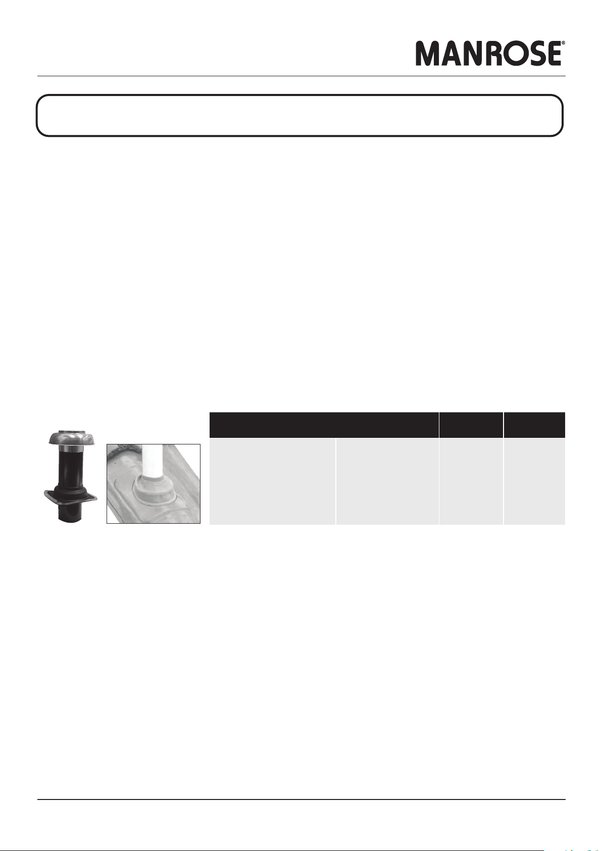
Roof Cowl Kits
REGULATIONS AND STANDARDS
Choosing the Right Fan to Comply
Fans cannot be selected on the basis of free-air performance only. Fans must now be selected on the basis of the complete installed system
performance for a designated room as per the table below.
1) Toilets only require ventilation if they have no openable windows
2) Simx recommends 40 l/s for laundries with unvented non-condensing tumble dryers as covered in AS 1668: Part 2 2012
Recent unregulated extract fan practices in New Zealand has trended to basic, low pressure axial fan products, as installed system performance has
not been defined for independent inspection testing and compliance signed off by local authorities.
New Zealand Building Code and Healthy Homes
The following two category requirements have been established for mandatory extraction ventilation in New Zealand.
The New Zealand Building Code for New Building Consents
The building regulatory system sets out a framework to promote good quality decisions being made during the Building Consent process. The
legislation and regulations work together, as the building regulatory system. The functional clauses of the NZ Building Code are grouped and
described by a letter and number. Clause G of the NZ Building Code covers services, with G4 setting out the performance requirements for
ventilation. The Building Code is enshrined in law. The New Zealand Building Code, G4, has been changed. This is supported by Acceptable Solution
G4/AS1 Fourth Edition that specifies mechanical ventilation in accommodation units that contain cooktops, showers and baths.
Residential Tenancy Regulations to the Healthy Homes Standards
Residential Tenancy Regulations for rental properties only is changing to the Healthy Homes Standards, sub part 4 - Ventilation Standards.
Complying with the Acceptable Solution G4/AS1
To comply, the mandatory mechanical extract system must deliver minimum airflow rates for the complete installed ventilation system. This means
that airflow rates must deliver the airflow after resistance of the ducting, internal and external grilles, as well as all other accessories, such as
backdraught shutters, are included.
Fan selection is important as some types are far better at overcoming ducting system pressure drops.
Additionally, the quality of the ducting system installation can be all important. Rigid duct systems are best as they are the most efficient. Good
installation practice is vital for flexible duct systems.
Room Airflow Rate (min.)
Intermittent Continuous
Toilet1) 25 l/s 10 l/s
Bathroom/shower 25 l/s 10 l/s
Laundry2) 40 l/s -
Kitchen 50 l/s 12 l/s
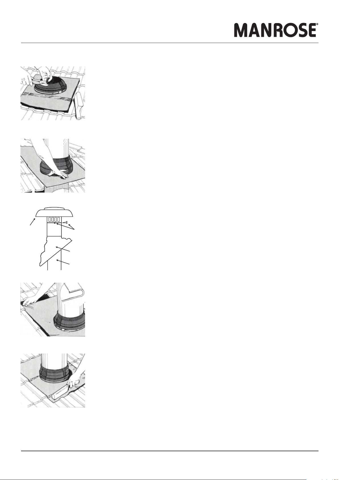
Duct Supports
Exterior Grille
Airflow
Airflow
Interior Grille
Sealant Cavity
Sleeve
Maximum length of
flexible ducting
Minimum radius =
diameter of ducting
Bathroom Kitchen
25 l/s Metres of Ducting 50 l/s Metres of Ducting
12345678910 12345678910
No. of
Bends
1
No. of
Bends
1
2 2
3 3
4 4
5 5
Fan Selection
Hyper150 EC Mixflo 150 Blue Jet
Preferred flexible
ducting route
Peaks and troughs
Restrictions

Installation Instructions Specifications are subject to change without notice Page 3
Roof Cowl Kits
INSTALLATION - TILE ROOF FLASHING
Trim the tile roof flashing cone to suit the tube size.
Slide the tile roof flashing down over the tube to the tile roof level. Water can be used as a lubricant.
Position the top end of the tube into the cowl.
The top edge should sit 20mm inside the cowl.
Drill through the three pilot holes and screw the cowl to the tube.
Flatten the sheet lead and form an anti-capillary fold (10mm x 2mm approx.).
Place the upper edge of the base underneath the tiles up stream.
Finish by dressing the apron to the surrounding tile area.
Turning the flexible flange back makes this simple.
When flashing a metal flue that has an exposed seam, apply a neutral cure sealant to seal the seam
from the underside of the cowl to the top of the tile roof flashing cone.
Ensure the installation is water tight.
Screws
Roof
Flashing
Tube
Aluminium
Cowl

Installation Instructions Specifications are subject to change without notice Page 4
Roof Cowl Kits
PUB0212 2008
INSTALLATION - FLEXIBLE DUCTING
Cut correct size hole in ceiling per fan supplier’s installation instructions.
From above, locate the fan shroud centrally over the fan mounting hole.
It is recommended that the base of the shroud is sealed against the ceiling lining using a suitable proprietary waterproof silicone sealant.
The ceiling lining and raw edge of the hole should also be sealed with a suitable paint sealer or other.
This simple procedure will ensure that any condensation that forms within the shroud will not permeate the ceiling lining over time.
Feed fan electrical cable into fan shroud using the supplied cord-grip grommet.
Install the fan, ensuring that the three fan mounting clamps on the top-side of the ceiling lining clamp down onto the 3 x shroud base web inserts.
This ensures that the shroud is firmly held in place.
For applicable oulet fan kits, fit the adapter to the fan exhaust spigot and secure the adapter/fan spigot joint with duct tape.
NOTE
Condensation is a physical phenomenon caused by temperature differentials. In order to minimise the effects of condensation, consideration should
be given to the following points:
• Insulation of ducting transitions through cold roof voids.
• Use of ‘RUN-ON’ timers, to fully evacuate the moist air generated by showers etc. This will subsequently have a drying effect within the duct.
• Use of a condensation trap. This could work out to be an expensive accessory. Contact Simx for further advice.
Fasten the tube to the roof truss or rafter using the clamp bracket supplied.
The tube/cowl must be mounted vertically to ensure weatherproofing.
Slide the flexible ducting over the tube and secure in place with duct tape.
Stretch the flexible ducting tightly to shroud the spigot
and cut the length accordingly.
Slide over the spigot and secure in place with duct tape.
INSTALLATION - FAN & SHROUD
Table of contents
Other Manrose Ventilation Hood manuals
Popular Ventilation Hood manuals by other brands

Geovent
Geovent CERA instruction manual

Faber
Faber FABULA BK RB instruction manual

KOBE
KOBE CH9136SQB-1 Installation instructions and operation manual

Crown
Crown FX 1560X user manual

Lapetek
Lapetek APOLLO-V installation instructions

Küppersbusch
Küppersbusch KD9575.0 Instructions for use and installation instructions