Manrose Roof Cowl Kits User manual

Installation Instructions Specifications are subject to change without notice Page 1
Roof Cowl Kits
Please ensure these instructions are read thoroughly before commencing installation
and that all documentation is left with the home owner on completion of installation
CAUTION
• Before use, please check that the supply voltage and that of the appliance are the same (see product rating label).
• All wiring and wiring connections must comply with national wiring rules and regulations.
• Any changes or modifications made or attempted to this product, without the prior written approval of the manufacturer, will void any and all
stated warranties.
• This appliance is not intended for use by persons (including children) with reduced physical, sensory or mental capabilities, or lack of
experience and knowledge, unless they are capable of, and have been given supervision or instruction concerning use of the appliance by a
person responsible for their safety.
• Children should be supervised to ensure that they do not play with the appliance.
• In case of damage to the supply cord, switch off the device and do not tamper with it. Damaged supply cords must only be repaired or
replaced exclusively by the manufacturer or by an appointed representative. Failure to comply with the above may endanger the safety of
people and cause possible damage to the whole system.
• Precautions must be taken to avoid the back-flow of gases into the room from the open flue of gas or other fuel-burning appliances.
TECHNICAL
Description Duct
(mm) Order Code
Medium Duty 200 DCT3603
Heavy Duty 200 DCT3604
• For retrofit applications just cut and attach supplied clips to hold seam together.
• Suitable for roof pitches up to 40°.
• Provides 10 - 20mm continuous contact with flashed tube providing a watertight seal.
• Clear markings make for easier cutting to tube size.

Installation Instructions Specifications are subject to change without notice Page 2
Roof Cowl Kits
REGULATIONS AND STANDARDS
Choosing the Right Fan to Comply
Fans cannot be selected on the basis of free-air performance only. Fans must now be selected on the basis of the complete installed system
performance for a designated room as per the table below.
1) Toilets only require ventilation if they have no openable windows
2) Simx recommends 40 l/s for laundries with unvented non-condensing tumble dryers as covered in AS 1668: Part 2 2012
Recent unregulated extract fan practices in New Zealand has trended to basic, low pressure axial fan products, as installed system performance has
not been defined for independent inspection testing and compliance signed off by local authorities.
New Zealand Building Code and Healthy Homes
The following two category requirements have been established for mandatory extraction ventilation in New Zealand.
The New Zealand Building Code for New Building Consents
The building regulatory system sets out a framework to promote good quality decisions being made during the Building Consent process. The
legislation and regulations work together, as the building regulatory system. The functional clauses of the NZ Building Code are grouped and
described by a letter and number. Clause G of the NZ Building Code covers services, with G4 setting out the performance requirements for
ventilation. The Building Code is enshrined in law. The New Zealand Building Code, G4, has been changed. This is supported by Acceptable Solution
G4/AS1 Fourth Edition that specifies mechanical ventilation in accommodation units that contain cooktops, showers and baths.
Residential Tenancy Regulations to the Healthy Homes Standards
Residential Tenancy Regulations for rental properties only is changing to the Healthy Homes Standards, sub part 4 - Ventilation Standards.
Complying with the Acceptable Solution G4/AS1
To comply, the mandatory mechanical extract system must deliver minimum airflow rates for the complete installed ventilation system. This means
that airflow rates must deliver the airflow after resistance of the ducting, internal and external grilles, as well as all other accessories, such as
backdraught shutters, are included.
Fan selection is important as some types are far better at overcoming ducting system pressure drops.
Additionally, the quality of the ducting system installation can be all important. Rigid duct systems (see page 102) are best as they are the most
efficient. Good installation practice is vital for flexible duct systems.
Room Airflow Rate (min.)
Intermittent Continuous
Toilet1) 25 l/s 10 l/s
Bathroom/shower 25 l/s 10 l/s
Laundry2) 40 l/s -
Kitchen 50 l/s 12 l/s
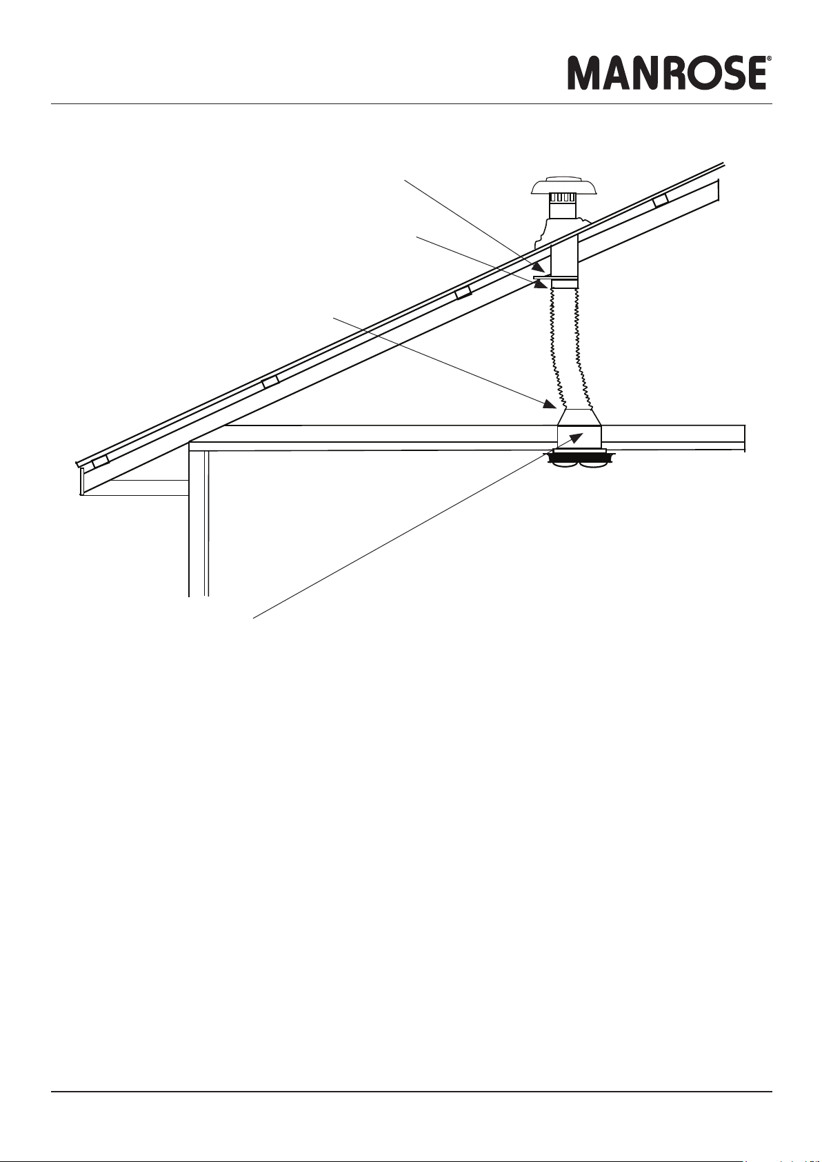
Duct Supports
Exterior Grille
Airflow
Airflow
Interior Grille
Sealant Cavity
Sleeve
Maximum length of
flexible ducting
Minimum radius =
diameter of ducting
Bathroom Kitchen
25 l/s Metres of Ducting 50 l/s Metres of Ducting
12345678910 12345678910
No. of
Bends
1
No. of
Bends
1
2 2
3 3
4 4
5 5
Fan Selection
Hyper150 EC Mixflo 150 Blue Jet
Preferred flexible
ducting route
Peaks and troughs
Restrictions

Installation Instructions Specifications are subject to change without notice Page 3
Roof Cowl Kits
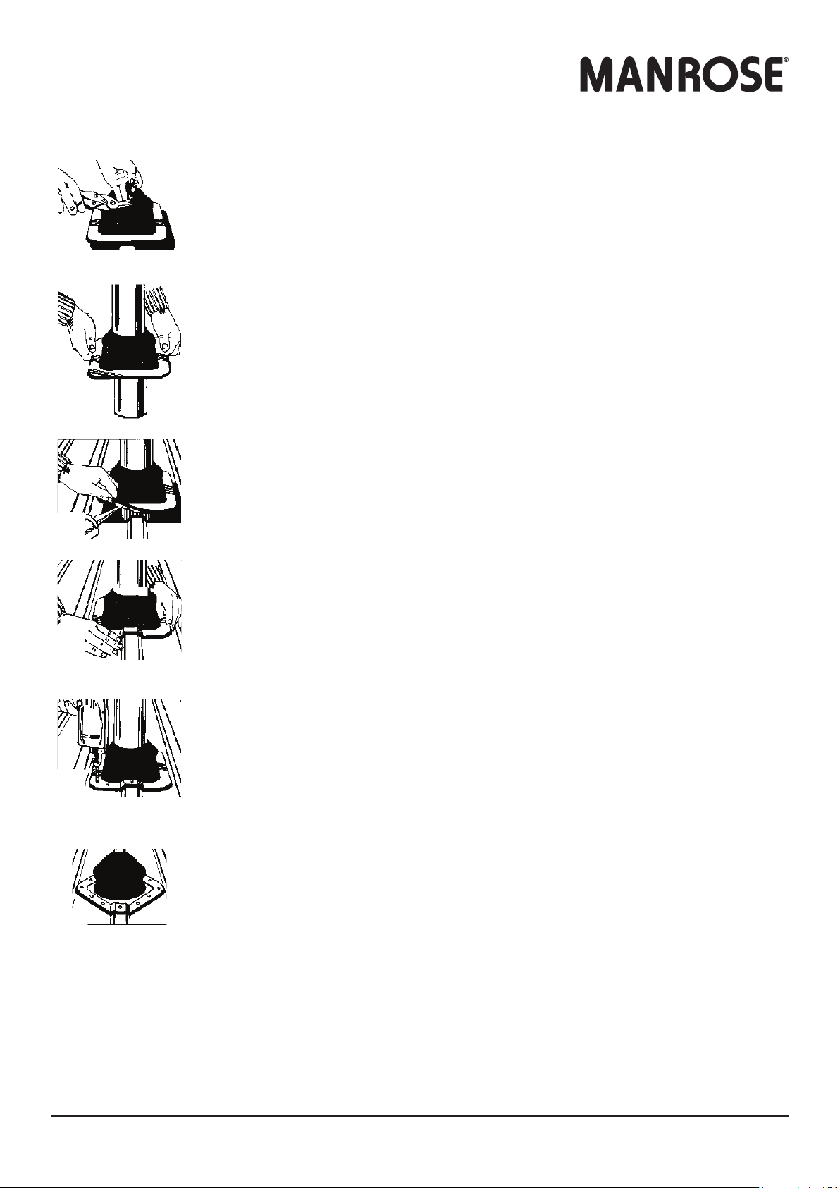
INSTALLATION - ROOF FLASHING: STANDARD APPLICATION
Cut the pliable roof flashing sleeve on the 190/200 marking
Slide the roof flashing down over the tube. Water can be used as a lubricant.
Position the top end of the tube into the cowl.
The top edge should sit 20mm inside the cowl.
Drill through the three pilot holes and screw the cowl to the tube.
You can now proceed to the actual roof installation.
Cut a neat hole in the roofing material with minimal clearance for the tube.
Insert the tube through the hole.
Apply a neutral cure silicon sealant on the underside of the flange.
Turning the flexible flange back makes this simple.
Press the roof flashing into the contours of the roof configuration.
Fasten the roof flashing to the roof using self drilling washered screws or sealed rivets.
Drill a 5mm clearance hole in the flange for each screw.
The screws can be driven into the roof without the need for a pilot drill hole, or use a 2.5mm drill.
Fit the fasteners progressively outward in opposing pairs to avoid gaps.
In certain applications it may be advantageous to install the flashing on the diamond or bias.
This particular installation method is especially suitable when having to seal enlarged holes, for penetrations
on steep pitched roofs.
Screws
Roof
Flashing
Tube
Aluminium
Cowl
Installation Instructions Specifications are subject to change without notice Page 4
Roof Cowl Kits
INSTALLATION - ROOF FLASHING: RETROFIT APPLICATION
Cut the pliable roof flashing sleeve on the 190/200 marking and trim to suit tube size..
Cut the roof flashing seam and aluminium base with sharp tin snips.
Apply a liberal bead of silicone to one side of the cut seam,
With the seam in a downstream position wrap the cone around pipe and attach the first double clip at the top
of the seam using multigrips.
Attach the remaining clips working down from the top of the cone to the base.
Apply a neutral cure silicon sealant on the underside of the flange.
Turning the flexible flange back makes this simple.
Press the roof flashing into the contours of the roof configuration.
Using self drilling washered screws or sealed rivets, fasten the roof flashing to the roof by placing fasteners on
either side of the seam first and then fitting fasteners progressively outward in opposing pairs to avoid gaps.
Apply sealant to the top of the base closure and any other potential leak areas.
In certain applications it may be advantageous to install the flashing on the diamond or bias.
This particular installation method is especially suitable when having to seal enlarged holes, for penetrations
on steep pitched roofs.
Installation Instructions Specifications are subject to change without notice Page 5
Roof Cowl Kits
INSTALLATION - DUCTING
INSTALLATION - FAN & SHROUD
Cut correct size hole in ceiling per fan supplier’s installation instructions.
From above, locate the fan shroud centrally over the fan mounting hole.
It is recommended that the base of the shroud is sealed against the ceiling lining using a suitable proprietary waterproof silicone sealant.
The ceiling lining and raw edge of the hole should also be sealed with a suitable paint sealer or other.
This simple procedure will ensure that any condensation that forms within the shroud will not permeate the ceiling lining over time.
Feed fan electrical cable into fan shroud using the supplied cord-grip grommet.
Install the fan, ensuring that the three fan mounting clamps on the top-side of the ceiling lining clamp down onto the 3 x shroud base web inserts.
This ensures that the shroud is firmly held in place.
For applicable oulet fan kits, fit the adapter to the fan exhaust spigot and secure the adapter/fan spigot joint with duct tape.
NOTE
Condensation is a physical phenomenon caused by temperature differentials. In order to minimise the effects of condensation, consideration should
be given to the following points:
• Insulation of ducting transitions through cold roof voids.
• Use of ‘RUN-ON’ timers, to fully evacuate the moist air generated by showers etc. This will subsequently have a drying effect within the duct.
• Use of a condensation trap. This could work out to be an expensive accessory. Contact Simx for further advice.
Fasten the tube to the roof truss or rafter using the clamp bracket supplied.
The tube/cowl must be mounted vertically to ensure weatherproofing.
Slide the flexible ducting over the tube and secure in place with duct tape.
Stretch the flexible ducting tightly to shroud the spigot
and cut the length accordingly.
Slide over the spigot and secure in place with duct tape.
PUB1309 2008
Table of contents
Other Manrose Ventilation Hood manuals


Popular Ventilation Hood manuals by other brands

inventum
inventum AKB9004RGT instruction manual

Teka
Teka DHT 85 Series user manual

AIRFORCE
AIRFORCE F139 A Instruction on mounting and use

Bosch
Bosch DWW092460B Installation Instructions Operating and installation instructions

Kuppersbusch
Kuppersbusch KD 9550.0 Service manual

Bertazzoni
Bertazzoni Heritage Series installation instructions


