Mantracourt DSCUSB User manual
DSCUSB Standard User Manual
mantracourt.com
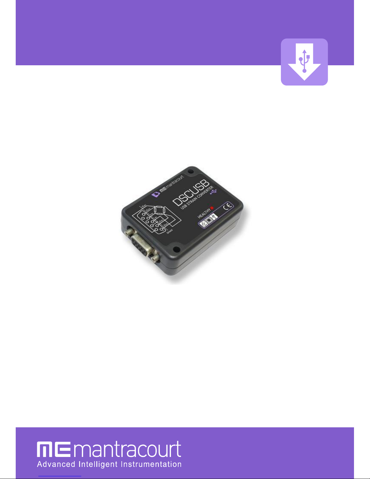
DSCUSB
Digital Sensor Card USB –Strain Gauge Input

Mantracourt Electronics Limited - DSCUSB Standard Manual
1
Contents
Chapter 1 Introduction........................................................................................................................................................2
Overview...........................................................................................................................................................................2
Manual Scope...................................................................................................................................................................2
LED Status Indication......................................................................................................................................................2
Chapter 2 Getting Started...................................................................................................................................................3
Communications Interface Information ......................................................................................................................3
DSC Toolkit.......................................................................................................................................................................3
What Can The Toolkit Do? ........................................................................................................................................................................... 3
Installing DSC Toolkit..................................................................................................................................................................................... 3
Connecting the Module to the Computer ...................................................................................................................4
Using the Found New Hardware Wizard................................................................................................................................................ 4
Using the Software.......................................................................................................................................................................................... 5
Information Page......................................................................................................................................................................................... 6
Home Page .................................................................................................................................................................................................... 8
Save and Restore Page ............................................................................................................................................................................. 9
Trend Chart Page ......................................................................................................................................................................................10
Logging Page..............................................................................................................................................................................................12
Data Rates and Filter Page ....................................................................................................................................................................14
Calibration Page ........................................................................................................................................................................................17
Calibration ................................................................................................................................................................................................18
Auto Calibration ................................................................................................................................................................................18
Table Calibration ...............................................................................................................................................................................18
Simple Unit Conversion..................................................................................................................................................................19
Shunt calibration ...............................................................................................................................................................................20
System Zero.............................................................................................................................................................................................20
Limits ..........................................................................................................................................................................................................21
Units............................................................................................................................................................................................................21
Advanced Calibration Page...................................................................................................................................................................22
Chapter 3 Installation ....................................................................................................................................................... 23
Identifying Strain Gauge Connections .......................................................................................................................23
9 way D Connector Pin-outs .....................................................................................................................................................................23
4-wire load cell ...............................................................................................................................................................................................23
6-wire load cell ...............................................................................................................................................................................................23
Temperature Sensor (Optional)................................................................................................................................................................24
Chapter 4 Specifications .................................................................................................................................................. 25
Technical Specifications ...............................................................................................................................................25
Dimensions & Mounting..............................................................................................................................................26
External Dimensions.................................................................................................................................................................................26
LED Position ................................................................................................................................................................................................26
Mounting Holes.........................................................................................................................................................................................26
DIN Rail Mounting (Optional Kit)........................................................................................................................................................27
Cable Clearance .........................................................................................................................................................................................27
Cable Retention .........................................................................................................................................................................................28
Environmental Approvals ................................................................................................................................................ 28
CE Approvals....................................................................................................................................................................................................28
Warranty............................................................................................................................................................................. 28

Mantracourt Electronics Limited - DSCUSB Standard Manual
2
Chapter 1 Introduction
This chapter provides an introduction to the DSCUSB products, describing the product range and main features.
Overview
The DSCUSB product family comprises of Digital Sensor Cards that connect sensors to your PC via USB.
The DSCUSB product is a compact, high-precision Strain Gauge Converter; converting a strain gauge sensor input to
a digital output and is connected to a PC via a USB port. They allow high precision measurements to be made and
communicated directly to a PC and is aimed at applications which require high-accuracy measurement repeatability.
With the appropriate drivers installed, the DSCUSB appears as a virtual serial port to the PC.
Simply by plugging the device into a PC, data can be extracted from most strain gauge bridge input sensors and
acquired by software which allows data manipulation removing the need for amplifiers, filters & multimeters.
Free-standing module fitted with 9-way ‘D’ type socket for load cell and optional temperature sensor connections.
Micro USB socket accepts a USB lead with type ’A’ connector at the PC end.
Manual Scope
This manual covers only the Standard level of functionality and calibration and assumes the operator is going to use
the DSC Toolkit as a means of configuration and to extract data from the module.
The DSCUSB may have already been connected to a loadcell and calibrated in which case this is the only manual you
will need to refer to.
A separate manual covers the Advanced functionality which includes loadcell profiling calibration, information on
writing your own communication software and advice on OEM production techniques.
If you have purchased this module and intend to connect it to a loadcell and perform linearization or temperature
compensation then you will need to refer to the DSCUSB Advanced Manual.
Please note that your DSCUSB module may have had the advanced features locked and if this is the case then you
will only be able to use the features documented in this manual.
LED Status Indication
The module indicates status via a flashing red Healthy LED.
With no load cell connected The LED of the DCell or DSC should flash OFF for 100ms every 500ms (LED will be ON
but flash off for a tenth of a second every half a second).
If a load cell is connected and there are no errors then the LED will Flash ON for 100mS then OFF every 500ms (LED
will be off but flash on for a tenth of a second every half a second).

Mantracourt Electronics Limited - DSCUSB Standard Manual
3
Chapter 2 Getting Started
Please ensure that software is installed before connecting the module to your PC
This chapter explains how to connect to a DSCUSB for the first time and how to get it working.
Communications Interface Information
DSCUSB modules can connect to a PC by plugging into a USB port and do not require an external power supply as
they appear as a ‘single unit load’ i.e. they draw <100mA.
Appropriate drivers must be installed which are bundled with the DSC Toolkit. These create a virtual serial port
allowing the DSCUSB to appear to the PC as a normal COM port device.
DSC Toolkit
The DSC Toolkit is a simple configuration tool designed specifically for configuring DSCUSB modules.
This toolkit allows configuration, calibration, logging and parameter management of the modules.
What Can The Toolkit Do?
Communications with a single module at a time to do the following:
Viewing of input with enunciators for integrity and range errors.
Two point auto calibration by application of known weight.
Setting System Zero and under and over range limits.
Select measurement rate and filter settings.
Save module settings including user calibration and ability to restore to same or different USB DSC modules.
Log input value to a CSV file at up to 100Hz which can be analysed in Microsoft Excel.
Trend chart view of live input. Exportable image and data.
Easily switch to alternative engineering units (If module has been previously calibrated)
Advanced Calibration (Not covered in this manual, see DSCUSB Advanced Manual)
o5 point temperature compensation
o7 point linearization
oLockable calibration
Installing DSC Toolkit
Install the DSC Toolkit software by inserting the CD in the CD ROM drive. This should start the ‘AutoRun’ process,
unless this is disabled on your computer.
(If the install program does not start of its own accord, run SETUP.EXE on the CD by selecting ‘Run’ from the ‘Start
Menu’ and then entering D:\SETUP, where Dis the drive letter of your CD-ROM drive).
The installation software pre-installs the required drivers so that they can be automatically found when the hardware
is plugged in later on.
After the software has been installed please connect the module and see the next section
before running the DSC Toolkit

Mantracourt Electronics Limited - DSCUSB Standard Manual
4
Connecting the Module to the Computer
Connect to a spare USB port on the Windows PC using the cable provided with the module.
Using the Found New Hardware Wizard
Connecting the module will cause the following dialog windows to appear. NOTE: Different operating systems may
present different dialog windows but the dialogs shown below should allow you make the correct choices regardless
of operating system.
The ‘Found New Hardware Wizard’ should now appear.
Select ‘No, not at this time’ so that the wizard does not
try searching online for a driver.
Click ‘Next’.
Now the wizard will start searching for the drivers.
The wizard should then proceed with installing the
software drivers.
Please note that there are two interfaces to the hardware
so that there are two drivers that will be installed
The USB DSC Port and the USB DSC Bus.
So the next dialog box you will see will be for the USB
DSC Port and the steps will be repeated from step 2.

Mantracourt Electronics Limited - DSCUSB Standard Manual
5
Using the Software
You can now launch the DSC Toolkit software.
The DSC Toolkit automatically detects the connected DSCUSB modules.
If there is only one DSCUSB connected when you launch the DSC Toolkit it will be automatically selected and the
Information Page will be displayed.
If multiple modules are detected you will be presented with a list to choose one from on the Home Page.
To connect to a module just click on one in the list to highlight it and click the ‘Connect’ button (Or just double click
the module in the list).
You will then see the Information page.
If no modules have been detected the ‘No modules detected’ message appears. Click the ‘OK’ button and the
‘Connect’ button changes to ‘Demo’. If you click the ‘Demo’ button you can navigate through the software
application with no module attached.

Mantracourt Electronics Limited - DSCUSB Standard Manual
6
Information Page
Click the icon to access the Information page.
This simply shows a large display and indicates if any error conditions are present by displaying an information box.
If the module has been allocated engineering units these may be displayed in the upper right of the LCD display.
‘Net’ Button
Clicking the ‘Net’ button will zero the display. When zeroed the ‘NET’ indicator will be displayed and the button
caption will change to ‘Gross’
Clicking the ‘Gross’ button will return the display to the actual value from the module. Note that with an
unconnected input you may not see any effect by clicking this button.

Mantracourt Electronics Limited - DSCUSB Standard Manual
7
‘Format’ Button
Clicking the ‘Format’ button allows you to select a new format for the displayed value. By using this you can hide
unwanted decimal places.
Just click the required display format in the list.
If any errors are detected these will be shown under the main display. The following screenshot shows an Integrity
error present.
The error box will disappear once the error is no longer present.

Mantracourt Electronics Limited - DSCUSB Standard Manual
8
Home Page
To select a different module just click the Home icon
You can then select a different module or plug in a different module. If you change the connected modules click the
‘Detect’ button to re-list the modules. Then select the required module from the list.

Mantracourt Electronics Limited - DSCUSB Standard Manual
9
Save and Restore Page
Click on the icon to open the Save & Restore page.
Clicking the ‘Save’buttons will allow you to specify a file to which the configuration of the connected module is
written.
Once saved this file can be selected, after clicking the ‘Restore’ button, and the settings restored to the same
module or to another module.

Mantracourt Electronics Limited - DSCUSB Standard Manual
10
Trend Chart Page
Click on the icon to open the Trend Chart page.
Data will be read from the module at the Measurement Rate (up to a maximum rate of 100Hz) and added to the
trend chart. You can see the current rate at which data is added at the top right of the chart.
The Measurement Rate can be selected in the Data Rates and Filter page by clicking .
The chart Y axis is auto scaling but you can select the view into a stored history of 10,000 data points. Just drag the
handles of the slider control under the chart to define the start and end point of the view.
The date and time of the first and last point on the chart are displayed in the lower left and right area under the
chart By clicking in the chart you can display a cursor and the date and time at the point of the cursor, also the data
point value will be displayed underneath the chart.
Clicking the Pause button to the left of the view control will pause the chart. This will stop data being added to
the chart. Please note that data will also cease to be added to the chart if you switch to another page by clicking any
of the icons on the toolbar.

Mantracourt Electronics Limited - DSCUSB Standard Manual
11
Right clicking the chart will display a pop-up menu allowing the following
Copy Chart Image
A graphic image of the chart will be copied to the clipboard.
Copy Chart Data
All the data points in the chart will be copied to the clipboard in a suitable format to be pasted into Microsoft Excel
and many other applications. The columns will be separated with Tab characters and each line terminated with a
carriage return.
This may take a few seconds to copy to the clipboard.
Clear Chart
You will be asked to confirm this action and if accepted the chart will be cleared of all data.
Mantracourt Electronics Limited - DSCUSB Standard Manual
12
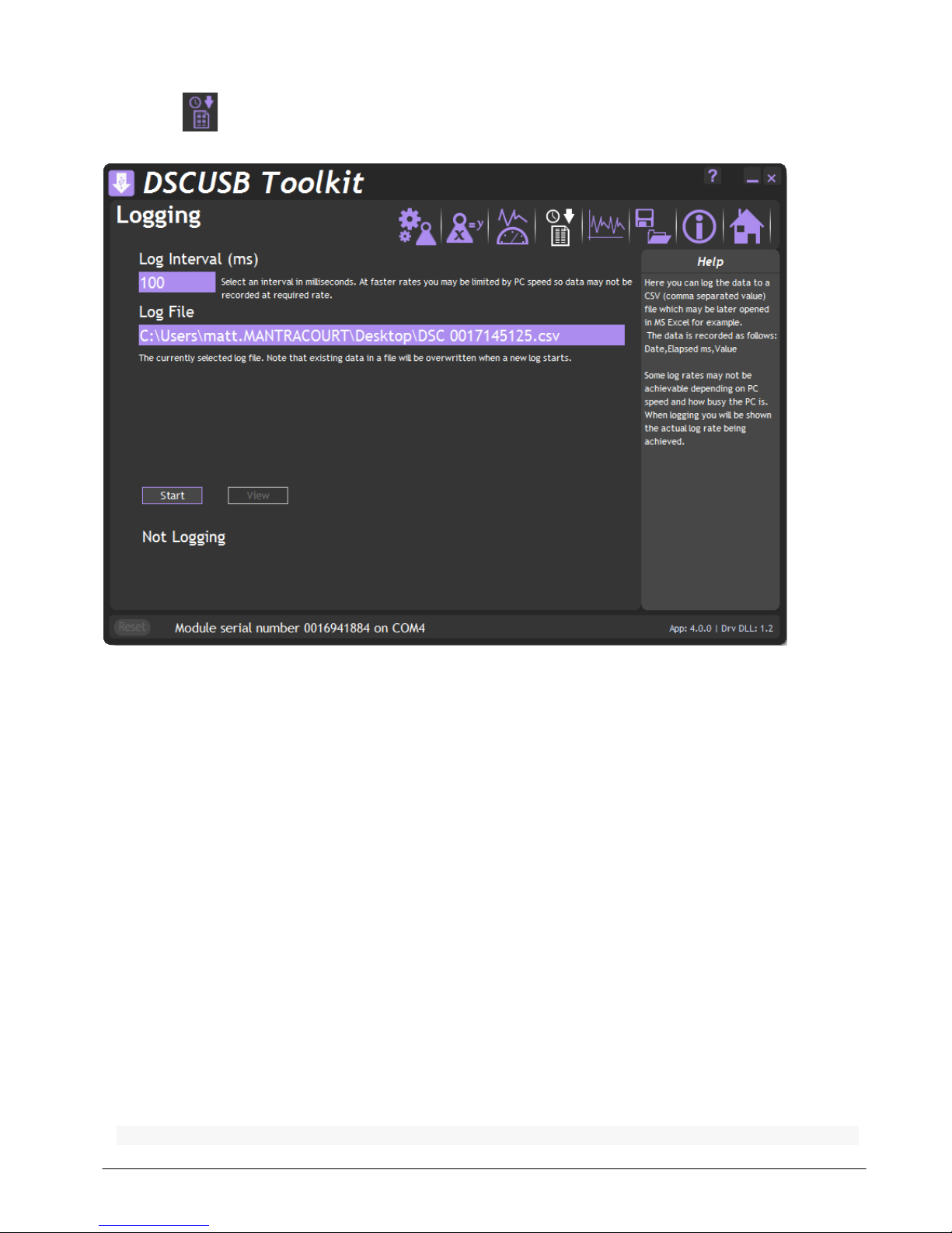
Logging Page
Click on the icon to open the Logging page.
The toolkit allows you to log data to a CSV (Comma Separated Value) file. This file will open in MS Excel when double
clicked.
Log Interval
Choose a Log Interval in milliseconds between 10 and 32000. 10mS will enable a log at 100Hz.
Log File
Select a file to log to. Note that each time the log starts it will erase any data already in the file.
Start
Clicking this button will start the log.
Stop
Clicking this button will stop the log.
View
When a log has just been stopped this button will launch the application associated with CSV files.
The format of the log file is as follows:
DateTime, Elapsed, Value

Mantracourt Electronics Limited - DSCUSB Standard Manual
13
Where:
DateTime is the date and time in long format
Elapsed is the time elapsed in milliseconds since the start of the log
Value is the numeric value logged
Example
08/06/2009 15:41:08,0,-3.25300008989871E-03
08/06/2009 15:41:08,10,-3.25300008989871E-03
08/06/2009 15:41:08,43,-3.25300008989871E-03
08/06/2009 15:41:08,60,-3.25300008989871E-03
If the measurement rate of the module is less than the rate at which you have chosen to log you will be informed
with a message as shown below.
Either reduce the Log Interval or reduce the Measurement Rate.
Once the logging starts the actual achieved log rate will be displayed at the bottom of the window. This is useful for
diagnostics such as when a heavily burdened PC is slowing the log rate.

Mantracourt Electronics Limited - DSCUSB Standard Manual
14
Data Rates and Filter Page
Click on the icon to open the Data Rates & Filter page.
This page allows you to select the measurement rate and filtering characteristics.
The measurement rate affects the noise free resolution which is indicated at the bottom of the page.
The filter level and filter steps affect the frequency response of the input which is indicated at the bottom of the
page.
The Dynamic filter is basically a recursive filter and therefore behaves like an electronic ‘RC’ circuit. It has two user
settings, a level set in the calibrated engineering units and the maximum number of steps (up to 255).
Instead of outputting every new value, a fraction of the difference between the new input value and the current
filtered value is added to the current filtered value to produce the filtering action.
If this difference is less than the value set in the Filter Level then the fractional amount added each time is
decremented until it reaches the minimum level set by FFST i.e. FFST is the limit of the divisor.
e.g. if Filter Steps = 10 the fractional part of the difference between the new value and the current filtered value will
be added to the current filtered value.
If a rapidly changing or step input occurs and the difference between the new input value and the current filtered
value is greater than the value set in Filter Level then the output of the filter will be made equal to the new input
reading i.e. the fractional amount of the new reading added to the current reading is reset to 1.
This allows the Filter to respond rapidly to fast moving input signals.

Mantracourt Electronics Limited - DSCUSB Standard Manual
15
When a step change occurs which does not exceed Filter Level, the new filtered value is calculated as follows:
New Filter Output value = Current Filter Output Value + ((Input Value - Current Filter Output Value) / Filter
Steps)
The time taken to reach 63% of a step change input (which is less than Filter Level) is dependant on the frequency
at which values are passed to the dynamic filter, set in Measurement Rate, multiplied by Filter Steps.
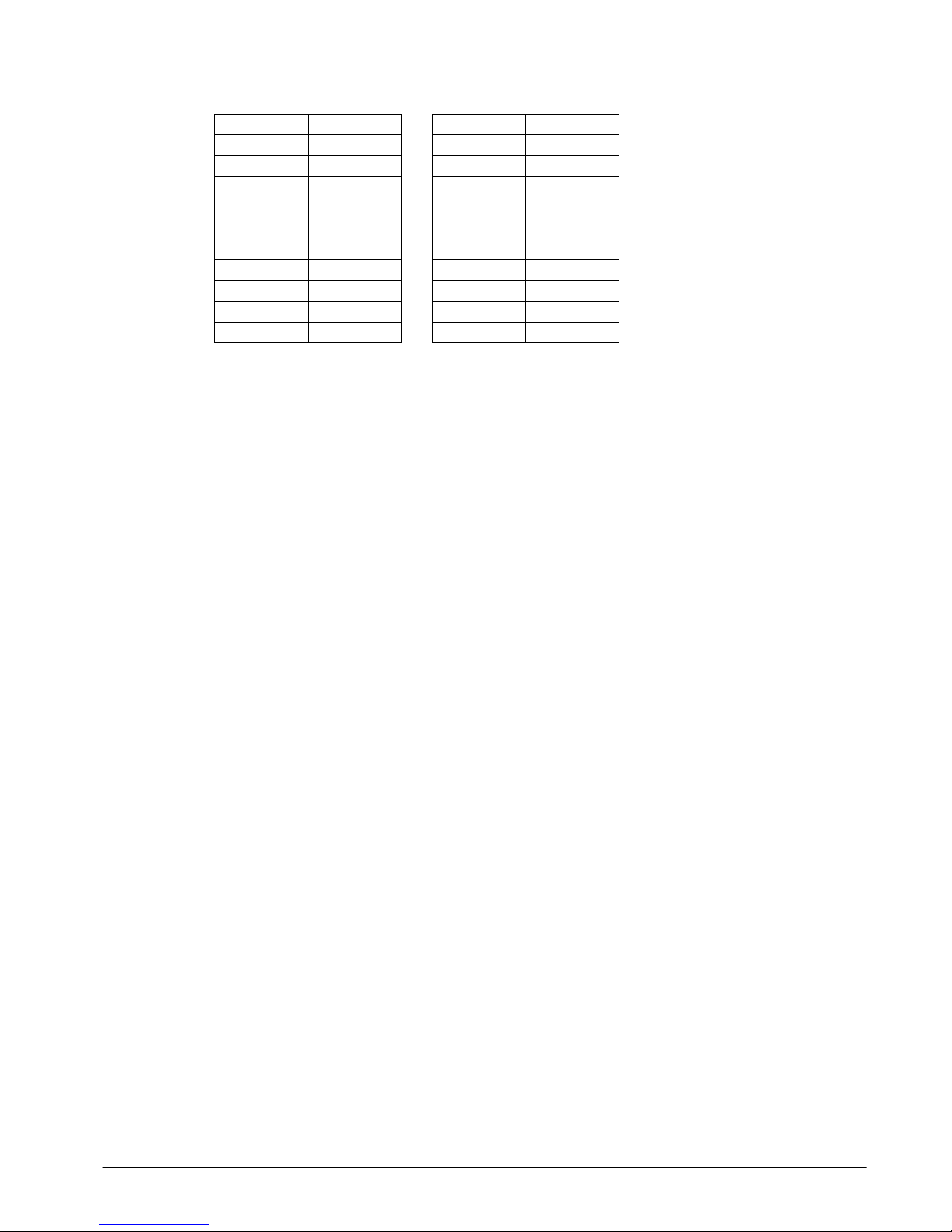
The table below gives an indication of the response to a step input which is less than Filter Level.
% Of Final Value
Time To settle
63%
Measurement Rate * Filter Steps
99%
Measurement Rate * Filter Steps * 5
99.9%
Measurement Rate * Filter Steps * 7
For example, If Measurement Rate is set to 100Hz = 0.01s and Filter Steps is set to 30 then the time taken to reach
a % of step change value is as follows.
% Of Final Value
Time To settle
63%
0.01 x 30 = 0.3 seconds
99%
0.01 x 30 x 5 = 1.5 seconds
99.9%
0.01 x 30 x 7 = 2.1 seconds
Mantracourt Electronics Limited - DSCUSB Standard Manual
16
The following table shows the number of updates ‘x Filter StepsT’ and the ‘% Error’ that the Filtered Output value
will differ from the constant Input Value.
x FFST
% Error
1
36.78794412
2
13.53352832
3
4.97870684
4
1.83156389
5
0.67379470
6
0.24787522
7
0.09118820
8
0.03354626
9
0.01234098
10
0.00453999
x FFST
% Error
11
0.00167017
12
0.00061442
13
0.00022603
14
0.00008315
15
0.00003059
16
0.00001125
17
0.00000414
18
0.00000152
19
0.00000056
20
0.00000021
Remember: if the step change in mV/V is greater than the value set in Filter Level then:
New Filter Output value = New Input Value i.e. the output jumps to the new input value and the internal working
value of Filter Steps is reset to 1. This is then incremented each update (set by Measurement Rate) until it reaches
the user set value of Filter Steps.
The filter can be disabled by entering zero for Filter Steps.
Note: The Filter Level is stored internally in the module in mV/V and is only presented to the operator via the
software as calibrated engineering units to make it easier. Therefore if the calibration is changed the displayed Filter
Level will change to reflect the new engineering units.
Mantracourt Electronics Limited - DSCUSB Standard Manual
17
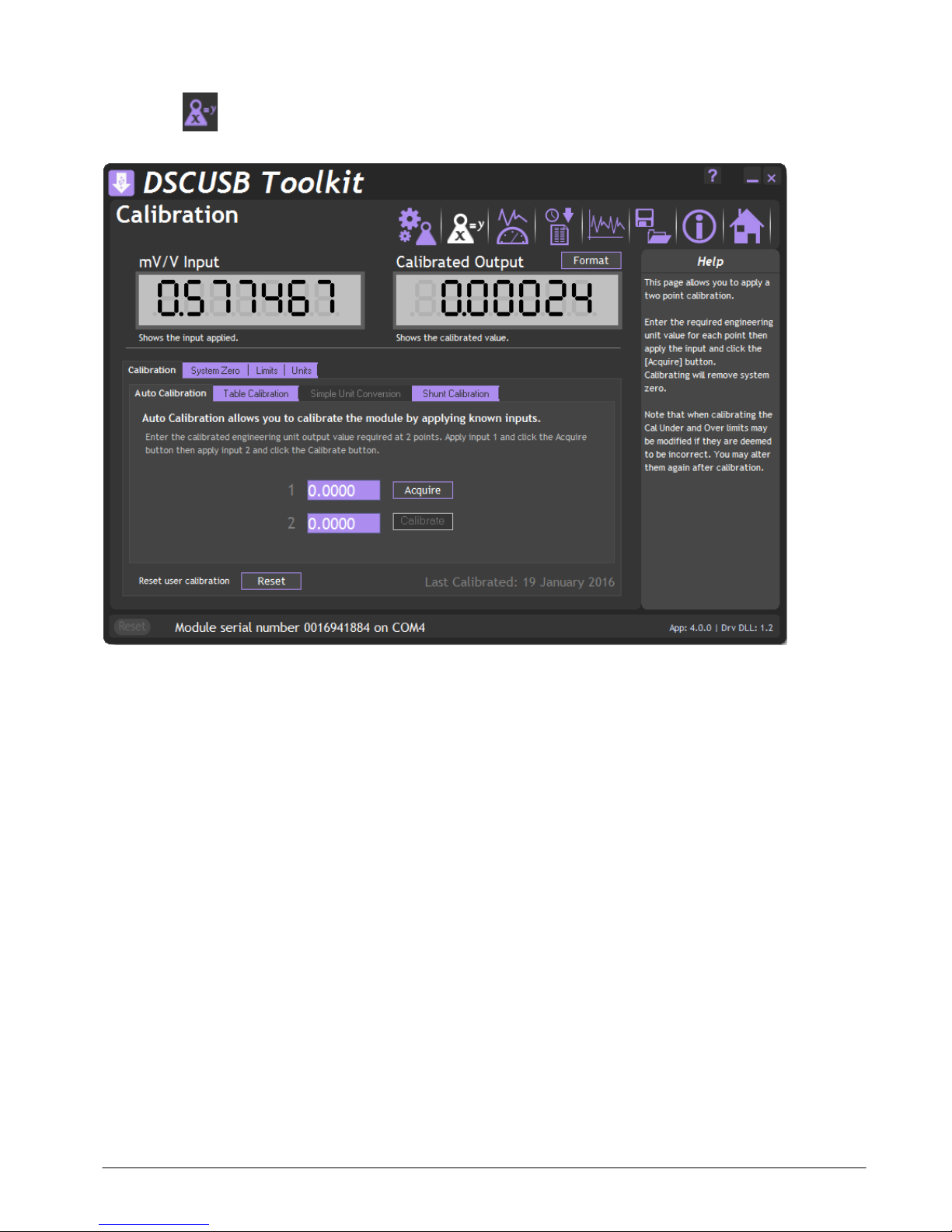
Calibration Page
Click on the icon to open the Calibration page.
This page allows you to calibrate the module using various methods, set limits, perform system zero and set units
description.
The page is separated by tabbed sections. Click in a tab to change sections.
Reset user calibration –Click the ‘Reset’ button to remove any custom calibration you have applied.
If the DSC module supports it the date of the last change to calibration settings will be displayed.
Mantracourt Electronics Limited - DSCUSB Standard Manual
18
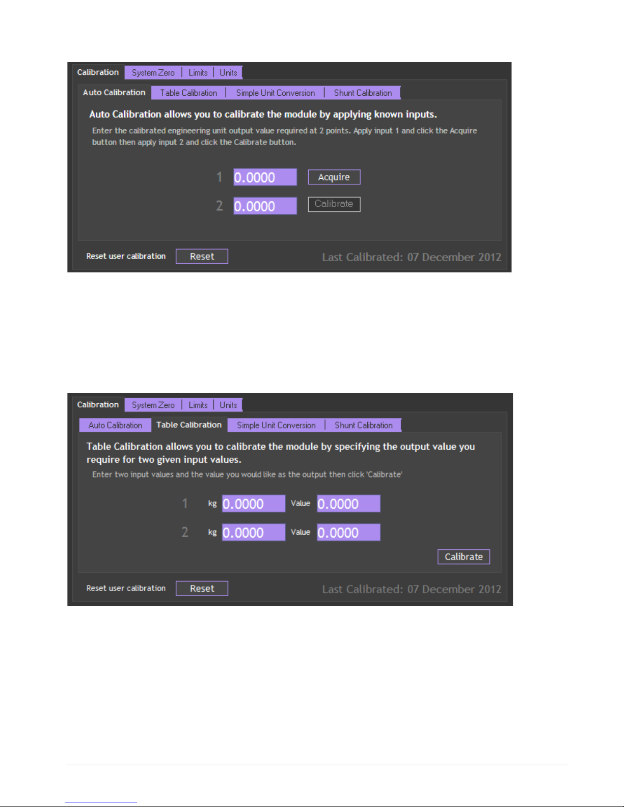
Calibration
Auto Calibration
The automatic calibration requires that you apply two known (ascending) weight in sequence. Just enter the required
engineering unit value for the two weights in the fields marked 1 and 2.
Next, apply the low weight and allow a settle time. Click the ‘Acquire’ button then apply the high weight. After
another settle time click the second ‘Acquire’ button and the calibration is complete.
Table Calibration
This option lets you calibrate direct from the loadcell manufacturers certificate without having to apply weights to
the input.
Choose 2 points from the loadcell certificate and enter the mV/V values and the weights on the certificate (or
convert the certificate weight to any other engineering unit of your choice) click the ‘Calibrate’ button and the
calibration is complete.

Mantracourt Electronics Limited - DSCUSB Standard Manual
19
Simple Unit Conversion
This tab will only be enabled if the module has been calibrated in the Advanced Calibration section.
If the Toolkit then recognises the calibrated units (In the example above it is kg) then you can click the box next to
‘Convert Output To Selected Units’ and you will be presented with a list of units that you can automatically convert
to.
Select the required units, click OK then click the ‘Convert’ button. The Toolkit will then alter the user calibration to
provide the output in the selected engineering units.
Other manuals for DSCUSB
1
Table of contents
Other Mantracourt Accessories manuals


