SICK RAY26 User manual

Described product
RAY26
Manufacturer
SICK AG
Erwin-Sick-Str. 1
79183 Waldkirch
Germany
Legal information
This work is protected by copyright. Any rights derived from the copyright shall be
reserved for SICK AG. Reproduction of this document or parts of this document is only
permissible within the limits of the legal determination of Copyright Law. Any modifica‐
tion, abridgment or translation of this document is prohibited without the express writ‐
ten permission of SICK AG.
The trademarks stated in this document are the property of their respective owner.
© SICK AG. All rights reserved.
Original document
This document is an original document of SICK AG.
8022178.168D | SICK
Subject to change without notice 3

Contents
1 General safety notes......................................................................... 5
2 Notes on UL approval........................................................................ 5
3 Intended use...................................................................................... 5
4 Operating and status indicators...................................................... 5
5 Mounting............................................................................................. 5
6 Electrical installation........................................................................ 6
7 Commissioning.................................................................................. 8
8 Troubleshooting................................................................................. 13
9 Disassembly and disposal............................................................... 14
10 Maintenance...................................................................................... 14
11 Technical data.................................................................................... 15
11.1 Electrical and mechanical data............................................................... 15
11.2 Dimensional drawing................................................................................ 16
11.3 Process data structure............................................................................. 16
CONTENTS
48022178.168D | SICK
Subject to change without notice

1 General safety notes
■Read the operating instructions before commissioning.
■
Connection, mounting, and configuration may only be performed by trained
specialists.
■
2006/42/EC
NO
SAFETY
Not a safety component in accordance with the EU Machinery Directive.
■
When commissioning, protect the device from moisture and contamination.
■These operating instructions contain information required during the life cycle of
the sensor.
2 Notes on UL approval
The device must be supplied by a Class 2 source of supply.
UL Environmental Rating: Enclosure type 1
3 Intended use
The RAY26 is an opto-electronic photoelectric retro-reflective sensor (referred to as
“sensor” in the following) for the optical, non-contact detection of objects, animals, and
persons. A reflector is required for this product to function. If the product is used for any
other purpose or modified in any way, any warranty claim against SICK AG shall become
void.
4 Operating and status indicators
1
2
43
1LED indicator green: supply voltage active
2BluePilot blue: AutoAdapt indicator during run mode
3Teach-in button
4LED indicator yellow: status of received light beam
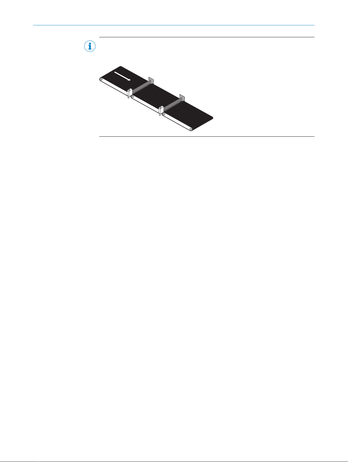
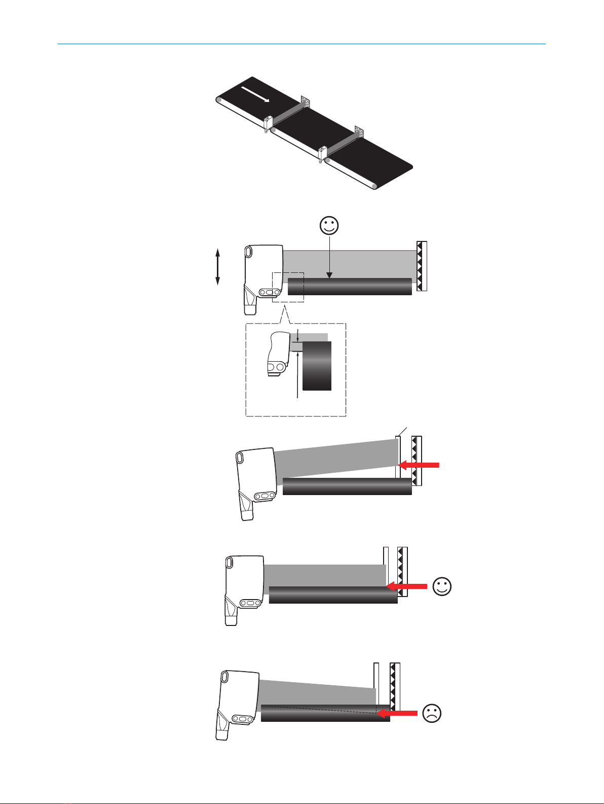
5 Mounting
Mount the sensor and the reflector using suitable mounting brackets (see the SICK
range of accessories). Align the sensor and reflector with each other.
Note the sensor's maximum permissible tightening torque of 0.65Nm.
GENERAL SAFETY NOTES 1
8022178.168D | SICK
Subject to change without notice 5

NOTE
RAY26P-XXXXX1XX (MDO ≥ 1 MM),
RAY26P-XXXXX3XX (MDO ≥ 3 MM):
Recommended position of installation: between conveyor belts or conveyor rollers
6 Electrical installation
Operation in standard I/O mode:
The sensors must be connected in a voltage-free state (UV = 0 V). The following informa‐
tion must be observed, depending on the connection type:
– Plug connection: note pin assignment
– Cable: wire color
Only apply voltage/switch on the voltage supply (UV > 0 V) once all electrical connec‐
tions have been established.
Operation in IO-Link mode: Connect the device to a suitable IO-Link master and inte‐
grate in the master or control via IODD/function block. The green LED indicator flashes
on the sensor. IODD and function block are available to download from www.sick.com
under the part number.
Explanation of the connection diagram (Tables 1-4):
Alarm = alarm output (see table 2 and table 4)
MF = multifunctional, programmable output
n. c. = not connected
QL1/C = switching output, IO-Link communication
6 ELECTRICAL INSTALLATION
68022178.168D | SICK
Subject to change without notice

DC: 10 ... 30 V DC, see "Electrical and mechanical data", page 15
Table 1: DC
RAY26P -24162xxxA00
-34162xxxA00
-1x162xxxA00 -24161xxxA00
-34161xxxA00
-1x161xxxA00
1+ (L+)
2MF
3- (M)
4QL1/C
Default: MF Q Q Q Q
Default: QL1/C Q Q Q Q
12
4 3
1 = BN
2 = WH
3 = BU
4 = BK
0.14 mm2
AWG26
12
4 3
1 = BN
2 = WH
3 = BU
4 = BK
0.14 mm2
AWG26
Table 2: DC
RAY26P -24165xxxA00
-34165xxxA00
-1x165xxxA00 -24163xxxA00
-34163xxxA00
-1x163xxxA00
1+ (L+)
2MF
3- (M)
4QL1/C
Default: MF Alarm Alarm Alarm Alarm
Default: QL1/C Q Q Q Q
12
4 3
1 = BN
2 = WH
3 = BU
4 = BK
0.14 mm2
AWG26
12
4 3
1 = BN
2 = WH
3 = BU
4 = BK
0.14 mm2
AWG26
Table 3: Push / pull
ELECTRICAL INSTALLATION 6
8022178.168D | SICK
Subject to change without notice 7

Q
Push-pull
(≤ 100 mA)
+ (L+)
Q
‒ (M)
+ (L+)
Q
‒ (M)
Q
Push-pull
(≤ 100 mA)
+ (L+)
Q
‒ (M)
+ (L+)
Q
‒ (M)
Table 4: Alarm
Alarm (≤ 100 mA)
+ (L+)
Alarm
‒ (M)
+ (L+)
Alarm
‒ (M)
7 Commissioning
1Alignment
Align the sensor with a suitable reflector. Select the position so that the red emitted light
beam hits the center of the reflector. The frontlens of the sensor and the reflector have to
be cleaned before teaching.
The sensor must have a clear view of the reflector, with no object in the path of the beam
[ see figure 1]. You must ensure that the optical openings of the sensor and reflector are
completely clear.
7 COMMISSIONING
88022178.168D | SICK
Subject to change without notice

Figure 1: Alignment
NOTE
The adjustment of the height (1) should be separated from the adjustment of the angle (2).
Figure 2: (1)
Figure 3: (2)
COMMISSIONING 7
8022178.168D | SICK
Subject to change without notice 9

1. Alignment of the light band in the gap between two conveyor belts
2. a) Alignment of the light band above the conveyor belt.
The light band has to be positioned parallel to the conveyor belt.
3 mm
b)
1
1 = metal plate
Take a metal plate and position it in front of the reflector. Rotate the sensor up a lit‐
tle. The light band is approx. 20 mm above the conveyor belt.
c)
Rotate the sensor down a little until the lower edge of the light band will hit the con‐
veyor belt (see light band on metal plate). Then fix the housing at the bracket. The
light band may not be moved further into the conveyor.
7 COMMISSIONING
10 8022178.168D | SICK
Subject to change without notice

NOTE
Tip:
1 Control of the setting: Switch on conveyor belt. In "idling mode" (conveyor belt moves
without material to be conveyed), the sensor must not switch. Switch on conveyor
belt. Place the goods in succession on the conveyor belt edges and in the middle on
the belt to check the reliable detection in three places.
NOTE
Video of commissioning:
2Sensing range
Reconcile the distance between the sensor and the reflector with the corresponding dia‐
gram see figure 4, page 11.
3
2
1
4
Figure 4: sensing range areas
Table 5: Definition sensing range
12 3 4
RAY26P-xxxxx1 PL80A 0 ... 1.5 m ≥ 1 mmA
RAY26P-xxxxx3 PL80A 0 ... 2 m ≥ 3 mmB
0 ... 3 m ≥ 5 mmB
0 ... 4.5 m ≥ 10 mmB
RAY26P-xxxxx5 PL80A 0 ... 3 m ≥ 5 mmA
RAY26P-xxxxx9 PL80A 0 ... 4.5 m ≥ 10 mmA
3Sensing range, on reflector 2
4Minimum detectable object (MDO)
AMDO is fix
BMDO ≥ 3 mm, ≥ 5 mm, ≥ 10 mm:
can be selected via IO-Link
Table 6: Sensing ranges on reflectors
0
0
1.5
0
1.5
0
1.5
0
Sensing range
4
(13.12)
Distance in m (feet)
1
(3.28)
3
(9.84)
5
(16.40)
2
(6.56)
1
2
3
Figure 5: RAY26P-xxxxx1
1PL80A
2PL40A
3PL30A
0
0
2
0
2
0
2
0
Sensing range
4
(13.12)
Distance in m (feet)
1
(3.28)
3
(9.84)
5
(16.40)
2
(6.56)
1
2
3
Figure 6: RAY26P-xxxxx3
1PL80A
2PL81
3PL100
COMMISSIONING 7
8022178.168D | SICK
Subject to change without notice 11

0
0
3
0
2
0
2
0
Sensing range
4
(13.12)
Distance in m (feet)
1
(3.28)
3
(9.84)
5
(16.40)
2
(6.56)
1
2
3
Figure 7: RAY26P-xxxxx5
1PL80A
2PL81
3PL100
0
0
4.5
0
3
0
3
0
Sensing range
4
(13.12)
Distance in m (feet)
1
(3.28)
3
(9.84)
5
(16.40)
2
(6.56)
1
2
3
Figure 8: RAY26P-xxxxx9
1PL80A
2PL81
3PL100
Minimum detectable object (MDO):
4
1
4
1
4
1
Sensing range setting:
1...3 sec.
1
2
3Conveyor blanking (only for RAY26P-xxxxx3)
The conveyor blanking allows a stepwise inactivation of the detection area (A = approx.
1 mm for each level) just above the conveyor belt. Thereby influences of the conveyor belt
(which causes false signals of the sensor) can be suppressed. The setting of the conveyor
blanking can be done via IO-Link with the index 238.
After setting the sensor has to be taught again (index 2, value 65).
7 COMMISSIONING
12 8022178.168D | SICK
Subject to change without notice

Table 7: Index 238
ISDU
Name Data
type Length Access Default
value Value/RangeIndex Sub-
Index
DEC HEX
238 0xE
E- Conveyor blanking Uint 8 Bit rw 0
0 = Deactivated
1 = Level 1
2 = Level 2
3 = Level 3
4 = Level 4
A
1
Figure 9: A = Level 1
A
1
Figure 10: A = Level 2
A
1
Figure 11: A = Level 3
A
1
Figure 12: A = Level 4
1Conveyor belt
8 Troubleshooting
The Troubleshooting table indicates measures to be taken if the sensor stops working.
LED indicator/fault pattern Cause Measures
Green LED flashes IO-Link communication None
Switching outputs do not
behave in accordance with see
table 3, page 7 and see
table 4, page 8
a) IO-Link communication
b) Change of the configuration
c) Short-circuit
a) None
b) Adjustment of the configu‐
ration
c) Check electrical connec‐
tions
The blue LEDs are very close
together
Front screen and/or reflector
is contaminated.
Cleaning of the optical sur‐
faces (sensor and reflector).
Yellow LED flashes Distance between sensor and
reflector is too large / light
band is not completely aligned
to the reflector / reflector is
not suitable / front screen
and/or reflector is contami‐
nated
Check sensing range / check
alignment / SICK reflector is
recommended / Cleaning of
the optical surfaces (sensor
and reflector)
Yellow LED does not light up
even though the light band is
aligned to the reflector and
there is no object in the path of
the beam
No voltage or voltage below
the limit values
Check the power supply,
check all electrical connec‐
tions (cables and plug connec‐
tions)
Voltage interruptions Ensure there is a stable power
supply without interruptions
Sensor is faulty If the power supply is OK,
replace the sensor
TROUBLESHOOTING 8
8022178.168D | SICK
Subject to change without notice 13

9 Disassembly and disposal
The sensor must be disposed of according to the applicable country-specific regula‐
tions. Efforts should be made during the disposal process to recycle the constituent
materials (particularly precious metals).
NOTE
Disposal of batteries, electric and electronic devices
•According to international directives, batteries, accumulators and electrical or
electronic devices must not be disposed of in general waste.
•The owner is obliged by law to return this devices at the end of their life to the
respective public collection points.
•
WEEE: This symbol on the product, its package or in this document, indi‐
cates that a product is subject to these regulations.
10 Maintenance
SICK sensors are maintenance-free.
We recommend doing the following regularly:
•Clean the external lens surfaces
•Check the screw connections and plug-in connections
No modifications may be made to devices.
Subject to change without notice. Specified product properties and technical data are
not written guarantees.
9 DISASSEMBLY AND DISPOSAL
14 8022178.168D | SICK
Subject to change without notice

11 Technical data
11.1 Electrical and mechanical data
RAY26P-xxxxx1 RAY26P-xxxxx3 RAY26P-xxxxx5 RAY26P-xxxxx9
Sensing range max.
(with reflector PL80A)
0 ... 1.5 m 0 ... 4.5 m 0 ... 3 m 0 ... 4.5 m
Light band dimen‐
sions / distance
approx.
24 mm x 9 mm (1 m) 55 mm x 9 mm (1m)
Minimum detectable
object (MDO)
≥ 1 mm ≥ 3 mm, 5 mm or 10
mm1)
≥ 5 mm ≥ 10 mm
Minimum distance
between sensor and
reflector
0 mm
Supply voltage UB10 ... 30 V DC
Current consumption ≤ 25 mA2), < 50 mA3)
Output current Imax. ≤ 100 mA
Communication mode COM2
IO-Link 1.1
Max. response time ≤ 3 ms4)
Switching frequency 170 Hz5)
Enclosure rating IP66, IP67
Protection class III
Circuit protection A, B, C, D6)
Ambient operating tem‐
perature
–40 °C ... +60 °C7)8)
1) RAY26P-xxxxx3: sensing range depends on the selected MDO (selectable via IO-Link):
3 mm = 0 ... 2 m
5 mm = 0 ... 3 m
10 mm = 0 ... 4.5 m
2) 16 VDC to 30 VDC, without load
3) 10 VDC to 16 VDC, without load
4) Signal transit time with resistive load in switching mode. Deviating values possible in COM2 mode.
5) With a light/dark ratio of 1:1 in switching mode. Deviating values possible in IO-Link mode.
6) A = UB-connections reverse polarity protected
B = inputs and output reverse-polarity protected
C = Interference suppression
D = outputs overcurrent and short-circuit protected
7) Avoid condensation on the front screen of the sensor and on the reflector.
8) Allowed temperature change after Teach +/- 20 K
TECHNICAL DATA 11
8022178.168D | SICK
Subject to change without notice 15

11.2 Dimensional drawing
Table 8: Dimensional drawing
1
24.6 (0.97)
8(0.31)
6.9 (0.27)
Ø 12.8 (0.50)
55 (2.17)
37.9 (1.49)
9.4 (0.37)
7.2
(0.28)
3
2
2
7.1 (0.28)
8.1 (0.32)
10.8 (0.43)
25 (0.98)
38.9 (1.53)
6.4
(0.25)
48.1 (1.89)
40 (1.57)
44.2 (1.74)
10
(0.39)
Ø 5.2 (0.2)
82.2 (3.24)
70 (2.76)
Ø 5.2 (0.2)
8.1 (0.32)
76.5 (3.01)
82.5 (3.25)
53.4 (2.10)
7
465
21
(0.83)
Figure 13: RAY26 with cable
M12
1
3
2
2
7.1 (0.28)
8.1 (0.32)
10.8 (0.43)
25 (0.98)
38.9 (1.53)
6.3 (0.25)
48.1 (1.89)
40 (1.57)
44.2 (1.74)
19.7
(0.78)
Ø 5.2 (0.2)
24.6 (0.97)
8(0.31)
6.9 (0.27)
82.2 (3.24)
70 (2.76)
Ø 5.2 (0.2)
17.1
(0.67)
7.9 (0.31)
76.5 (3.01)
82.5 (3.25)
55 (2.17)
37.9 (1.49)
9.4 (0.37)
53.3 (2.1)
63.9 (2.52)
21
(0.83)
7
465
Figure 14: RAY26 with connector
1Center of optical axis
2Fixing hole Ø 5.2 mm
3Connection
4BluePilot blue: AutoAdapt indicator during run mode
5Teach-in button
6LED indicator yellow: status of received light beam
7LED indicator green: supply voltage active
11.3 Process data structure
A00
IO-Link V1.1
Process data 2 byte
Byte 0: bits 15... 8
Byte 1: bits 7... 0
Bit 0 / Data type QL1 / Boolean
Bit 1 / Data type QL2 / Boolean
Bit 2 ... 15 / Description / Data type [empty]
11 TECHNICAL DATA
16 8022178.168D | SICK
Subject to change without notice

Beschriebenes Produkt
RAY26
Hersteller
SICK AG
Erwin-Sick-Str. 1
79183 Waldkirch
Deutschland
Rechtliche Hinweise
Dieses Werk ist urheberrechtlich geschützt. Die dadurch begründeten Rechte bleiben
bei der Firma SICK AG. Die Vervielfältigung des Werks oder von Teilen dieses Werks ist
nur in den Grenzen der gesetzlichen Bestimmungen des Urheberrechtsgesetzes zuläs‐
sig. Jede Änderung, Kürzung oder Übersetzung des Werks ohne ausdrückliche schriftli‐
che Zustimmung der Firma SICK AG ist untersagt.
Die in diesem Dokument genannten Marken sind Eigentum ihrer jeweiligen Inhaber.
© SICK AG. Alle Rechte vorbehalten.
Originaldokument
Dieses Dokument ist ein Originaldokument der SICK AG.
18 8022178.168D | SICK
Subject to change without notice

Inhalt
12 Allgemeine Sicherheitshinweise..................................................... 20
13 Hinweise zur UL Zulassung.............................................................. 20
14 Bestimmungsgemäße Verwendung............................................... 20
15 Betriebs- und Statusanzeigen.......................................................... 20
16 Montage.............................................................................................. 20
17 Elektrische Installation..................................................................... 21
18 Inbetriebnahme................................................................................. 23
19 Störungsbehebung............................................................................ 28
20 Demontage und Entsorgung............................................................ 29
21 Wartung.............................................................................................. 29
22 Technische Daten.............................................................................. 30
22.1 Elektrische und mechanische Daten....................................................... 30
22.2 Maßzeichnung........................................................................................... 31
22.3 Prozessdatenstruktur............................................................................... 31
INHALT
8022178.168D | SICK
Subject to change without notice 19

12 Allgemeine Sicherheitshinweise
■Lesen Sie vor der Inbetriebnahme des Geräts die Betriebsanleitung.
■
Der Anschluss, die Montage und die Konfiguration des Geräts dürfen nur
von geschultem Fachpersonal vorgenommen werden.
■
2006/42/EC
NO
SAFETY
Bei diesem Gerät handelt es sich um kein sicherheitsgerichtetes Bauteil im
Sinne der EU-Maschinenrichtlinie.
■
Bei der Inbetriebnahme ist das Gerät ausreichend vor Feuchtigkeit und Ver‐
schmutzung zu schützen.
■Die vorliegende Betriebsanleitung enthält Informationen, die während des Lebens‐
zyklus der Lichtschranke benötigt werden.
13 Hinweise zur UL Zulassung
The device must be supplied by a Class 2 source of supply.
UL Environmental Rating: Enclosure type 1
14 Bestimmungsgemäße Verwendung
Die RAY26 ist eine optoelektronische Reflexions-Lichtschranke (im Folgenden Sensor
genannt) und wird zum optischen, berührungslosen Erfassen von Sachen, Tieren und
Personen eingesetzt. Zur Funktion wird ein Reflektor benötigt. Bei jeder anderen Ver‐
wendung und bei Veränderungen am Produkt verfällt jeglicher Gewährleistungsan‐
spruch gegenüber der SICK AG.
15 Betriebs- und Statusanzeigen
1
2
43
1LED-Anzeige grün: Versorgungsspannung aktiv
2BluePilot blau: AutoAdapt-Anzeige im Run-Betrieb
3Teach-in-Taste
4LED-Anzeige gelb: Status des empfangenen Lichtstrahls
16 Montage
Sensor und Reflektor an geeignete Befestigungswinkel montieren (siehe SICK-Zubehör-
Programm). Sensor und Reflektor zueinander ausrichten.
Beachten Sie das maximal zulässige Anzugsdrehmoment von 0.65Nm.
12 ALLGEMEINE SICHERHEITSHINWEISE
20 8022178.168D | SICK
Subject to change without notice
Other manuals for RAY26
3
Table of contents
Languages:
Other SICK Accessories manuals

SICK
SICK GTB2 Flat Series User manual

SICK
SICK GRTE18 24 Series User manual

SICK
SICK MultiTask RAY10 Series User manual

SICK
SICK RMS1000 User manual

SICK
SICK SureSense HL18 Series User manual

SICK
SICK RMS3 Series User manual

SICK
SICK W24-2 User manual

SICK
SICK WS26 User manual

SICK
SICK GRL18 Series User manual

SICK
SICK SIM1004 User manual