Mantracourt UAB User manual

Mantracourt Electronics Limited UAB User Manual
1
Chapter 1 Introduction To The Universal Process Amplifier System......................................................... 4
Chapter 2 Installation................................................................................................................... 5
Environmental Requirements........................................................................................................... 5
Terminal Connections.................................................................................................................... 6
Section 1 -The Rack (RUA) Variant .................................................................................................... 7
Figure 2.1 - Rear view of Rack (RUA2)................................................................................................ 7
Figure 2.2 UAB Rear Connection Terminals ......................................................................................... 7
Figure 2.3 The 32 Way A & C (DIN41612) Connections............................................................................. 7
Figure 2.4 Rack Module Layout......................................................................................................... 8
Figure 2.5 LP2 Hand Held Programming Unit ........................................................................................ 8
Figure 2.6 RUA1 for External Programmer (LP2) .................................................................................. 8
Figure 2.7 RUA2 On-Board Programmer .............................................................................................. 8
Section 2 - The Surface Mount (SMP) Variant........................................................................................ 8
Figure 2.8 The IP65-ABS Case (LAB) Dimensions & Mounting Points ............................................................. 9
Figure 2.9 The DIN Rail Mounting (D2) Dimensions ................................................................................. 9
Figure 2.10 Stainless Steel Panel Mount & Programming Display Module, Dimensions & Mounting Points................ 9
Figure 2.11 LCS Stainless Steel Panel Cut Out...................................................................................... 10
Figure 2.12 Connection & Fitting Details for the Surface Mounted Amplifier (UAB).........................................10
Programmers for Surface Mount Variants ........................................................................................... 11
Figure 2.13 LP1 On-Board Programmer Unit ........................................................................................11
Figure 2.14 LP2 Remote hand Held Programmer Unit (UAB).....................................................................11
Chapter 3 Power Supplies ............................................................................................................12
Section 1 - The Rack Version (RS1) ................................................................................................... 12
Table 3.1.................................................................................................................................. 12
Table 3.2.................................................................................................................................. 12
Section 2 - The Surface Mount Versions (LS1 and LS3)............................................................................12
Figure 3.1 Power Supply LS1 Connections...........................................................................................13
Figure 3.2 LS3 Connections ............................................................................................................13
Chapter 4 Input Modules ..............................................................................................................14
Table 4.1 UADCV1 and UADCA1 Switch Configuration.............................................................................14
Figure 4.1 The UADC1 & UADCA1 Modules ..........................................................................................14
Figure 4.2 The UALV1 - LVDT Module Rear Panel Connections .................................................................. 14
Figure 4.3 LVDT Switch Settings ......................................................................................................15
Figure 4.4 Rear Panel Connections ...................................................................................................15
Figure 4.5 UAT1 & 2..................................................................................................................... 16
Figure 4.6 Thermocouple Connectors ................................................................................................16
Figure 4.7 RTD Module UAPT .......................................................................................................... 16
Figure 4.8 RTD Connections............................................................................................................17
Fast Strain Gauge The (UAFLC) Module.............................................................................................. 18
Figure 4.9 UAFLC Module...............................................................................................................18
Figure 4.10 UAFLC Connections.......................................................................................................18
Figure 4.11 the UADIA Modules........................................................................................................ 18
Figure 4.12 UADIA Connections .......................................................................................................18
Chapter 5 Output Modules............................................................................................................19
Section 1 - General Description.......................................................................................................19
Figure 5.1 Showing the Potentiometer for Gain & Offset Adjustment .........................................................19
Figure 5.2 UAFAO Connections........................................................................................................19
Section 2 - Digital Output Modules ................................................................................................... 20
Figure 5.3 RR1 Module..................................................................................................................21
Figure 5.4 LR1 Module .................................................................................................................. 21
Figure 5.5 Installation of LR1..........................................................................................................22
Figure 5.6 Connection to the Surface Mount/DIN Rail Version UAI²C (S) ......................................................22
Section 3 - The Communications Port Modules.....................................................................................22
Figure 5.7 LC1 Current Loop........................................................................................................... 23
Figure 5.8 IF25 Connecting Multiple Process Amplifiers ..........................................................................23
LC3 Isolated RS232/485 Communications Module..................................................................................23
Figure 5.9 LC3 Isolated RS232/485~Mode Connections ...........................................................................23

Mantracourt Electronics Limited UAB User Manual
2
Figure 5.10 Connecting Multiple Units on RS485...................................................................................24
Figure 5.11 LC3 RS232 Mode Connection to PC.....................................................................................24
Figure 5.12 LC3 RS232 Mode Connection to Printer ...............................................................................24
RC1 Communications Current Loop Module Connections .........................................................................25
Figure 5.13 RC1 Communication Connections ......................................................................................25
Figure 5.14 RC1 Baud Rate Selection................................................................................................. 25
Figure 5.15 Connecting Multiple Process Amplifiers...............................................................................26
RC3 RS232/485 Communication Connectors........................................................................................26
Figure 5.16 RC3 RS232/485 Communication Connections........................................................................26
Figure 5.17 - RC3 Baud Rate Selection...............................................................................................27
Section 4 Serial Communication Protocol ........................................................................................... 27
Fast MANTRABUS - selected when CP is 128 ........................................................................................27
Communications Commands...........................................................................................................28
Data Transmitted To Process Amplifier For Command 1 .........................................................................28
Table 5.1.................................................................................................................................. 33
Process Amplifier Printer Format..................................................................................................... 33
Chapter 6 The Amplifier Displays ...................................................................................................35
Figure 6.1 Programmer Unit Panel Layout (RUA2) ................................................................................ 35
Figure 6.2 LP2 Remote Hand Held Programmer Unit .............................................................................35
Figure 6.3 Programmer Unit Panel Layout (LP1) ...................................................................................35
Control Panel Guide..................................................................................................................... 36
Figure 6.4 Programmer Unit Panel Layout .......................................................................................... 36
Figure 6.5 Display Module Connections and Switch Settings.....................................................................37
Table 6.1.................................................................................................................................. 37
Chapter 7 Programming The Amplifiers ...........................................................................................38
Section 1 - Display & Programming Mnemonics .................................................................................... 38
Table 7.1 Configurable Parameters for Process Input.............................................................................38
Table 7.2 Configurable Parameters for Dual Input Modules......................................................................41
Configurable Parameters for UAFLC - Fast Strain Gauge Input Module ........................................................41
Table 7.3 Configurable Parameters ..................................................................................................42
Section 2 - Setting the Conditions for Linear Inputs............................................................................... 42
Figure 7.1 Linear Input Scaling........................................................................................................42
Method of Calculating IPL and IPH from any known input values ...............................................................42
Input Calibration Routine ..............................................................................................................43
Section 3 - The Temperature Input Modules (UAT1 & UAT2).....................................................................43
Table 7.4 - Thermocouple Input Codes .............................................................................................44
Table 7.5.................................................................................................................................. 44
Section 4 - The Rate/Totaliser Input Module (UARTL)............................................................................ 45
Setting up the Input.....................................................................................................................45
Table 7.6.................................................................................................................................. 45
Table 7.7 Input Configuration .........................................................................................................45
Setting the Prescaler....................................................................................................................45
Table 7.8.................................................................................................................................. 46
Rate Measurement.......................................................................................................................46
Period (Time measurement between pulses) ......................................................................................46
Input Code ................................................................................................................................ 46
Table 7.9.................................................................................................................................. 46
(i) Period in mSeconds ................................................................................................................. 46
Table 7.10 Period mS Fixed Scale .................................................................................................... 46
(ii) Period in µSeconds..................................................................................................................46
Table 7.11 Period µS Unity Scale (IPSF 1.0000) ....................................................................................46
Frequency................................................................................................................................. 46
Table 7.12................................................................................................................................. 47
Figure 7.2 Frequency Unity Scale Inputs ............................................................................................47
RPM......................................................................................................................................... 47
Table 7.13 RPM Unity Scale............................................................................................................ 47
Figure 7.3 RPM Unity Scale Range ....................................................................................................48
Count/Rate Scaling & Scaling/Rate ..................................................................................................48

Mantracourt Electronics Limited UAB User Manual
3
Scaling Example: -....................................................................................................................... 48
RTL Module Inputs ....................................................................................................................... 49
Figure 7.4 RTL Module Inputs..........................................................................................................49
Section 5 - Programming the Output Functions ....................................................................................49
Hysteresis (HYS).......................................................................................................................... 49
Latching Outputs (OL) .................................................................................................................. 50
Table 7.14 Output Latch Codes (OL) ................................................................................................. 50
Output Action (OA)......................................................................................................................50
Table 7.15 Output Action Codes (OA)................................................................................................ 50
Delay Timers.............................................................................................................................. 50
Delay On Timer........................................................................................................................... 50
Delay Off Timer.......................................................................................................................... 50
PID Functions............................................................................................................................. 50
PID Empirical Tuning .................................................................................................................... 51
Section 6 - Scaling the Analogue Outputs ...........................................................................................51
Output Scaling............................................................................................................................ 51
Figure 7.5 Analogue Output............................................................................................................ 51
Method of Calculating OPL & OPH from any known Output & Display Values.................................................52
Calibration................................................................................................................................ 52
Figure 7.6 Showing the Potentiometers for Gain and Offset Adjustment .....................................................52
Figure 7.7 Showing the Potentiometers for Gain & Offset Adjustment........................................................53
Chapter 8 Order Codes ................................................................................................................54
RUA Rack Mounted Universal Input Process Amplifier.............................................................................54
UAB Universal Amplifier ................................................................................................................54
SMP Surface Mount Process Indicator & Controller ................................................................................55
CE Approvals.............................................................................................................................. 56
Instrument Setup Record Sheet .......................................................................................................57
W A R R A N T Y..........................................................................................................................57

Mantracourt Electronics Limited UAB User Manual
4
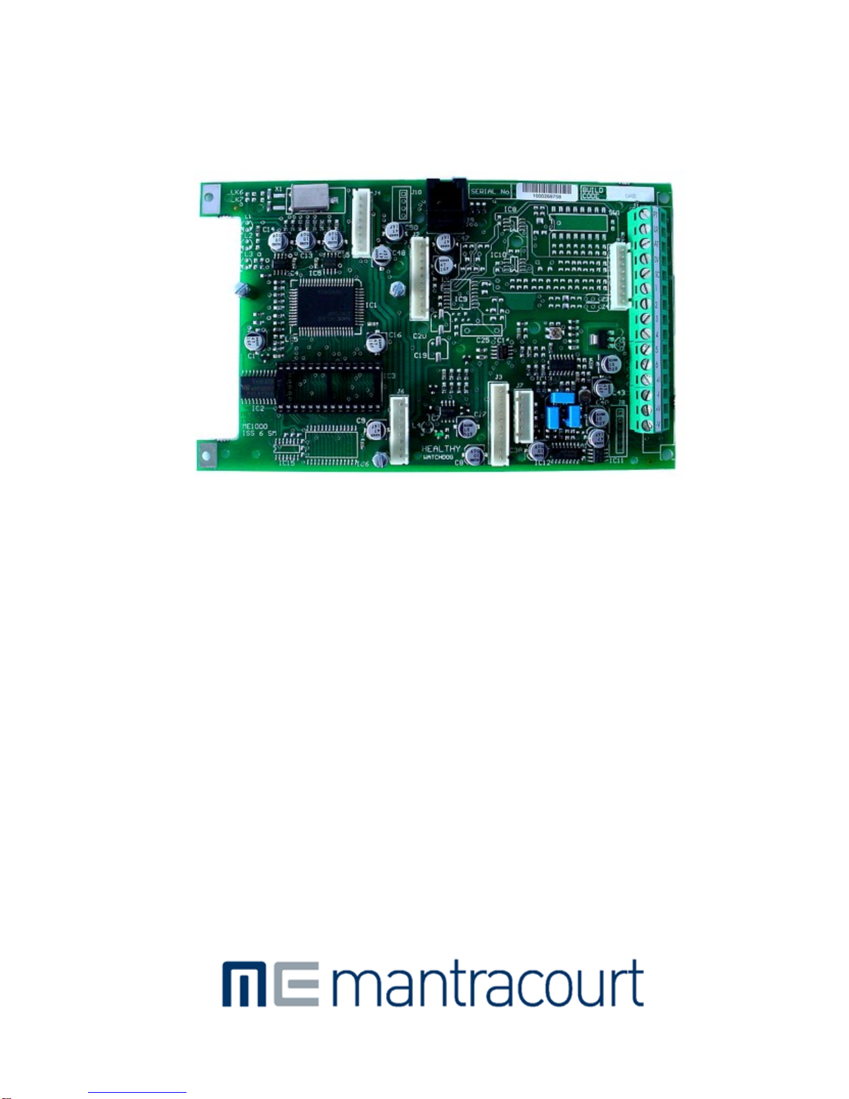
Chapter 1 Introduction To The Universal Process Amplifier System
The Mantracourt Electronics Universal Process Amplifier System is based upon a concept of modular construction. By
adopting such a concept, it is possible to offer a great deal of flexibility of construction, to meet the wide and
varying needs of system building.
The system is centred on a Eurocard sized amplifier PCB, which consists in its standard form of, Central Processing,
and voltage and current Analogue output ports. Facilities are provided to connect a series of ‘plug in ’ option boards
for inputs, relay and communications outputs together with mains and low voltage DC power supply options.
A special Fast Analogue output module is also available to complement a Fast Strain Gauge input option.
The modular concept offers the opportunity for assembly in Surface Mount, DIN Rail and 19-inch Rack variants.
The system concept is described in diagrammatic form with the range of options listed. The options will be
described under the various Chapters as follows:
1. Introduction
2. Installation requirements
3. Power Supplies
4. Input Modules
5. Output Modules & Communications Information
6. The Amplifier Displays
7. Programming the Amplifier including essential INPUT CALIBRATION ROUTINES, which must be actioned. See
Chapter 7
8. Order Codes
9. Specifications

Mantracourt Electronics Limited UAB User Manual
5
Chapter 2 Installation
In order to maintain compliance with the EMC Directive 2004/108/EC the following installation recommendations
should be followed.
Inputs:
Comms Port:
Analogue
Output:
Use individually screened twisted multipair cable. (e.g. FE 585 - 646)
The pairs should be :
pins 1 & 6
pins 2 & 5
pins 3 & 4
Terminate all screens at pin 1 of the input. The screens should not be
connected at the transducer end of the cables.
Use individually screened twisted multipair cable. (e.g. FE 118-2117)
The pairs should be:
-Tx & +Tx
-Rx & +Rx
Terminate screens at pin 1 of the input .
The screens should not be connected at the host port.
Use screened twisted pair cable. (e.g. RS 626-4761)
Terminate screen at pin 1 of the input.
The screen should not be connected at the host port.
Pin 1 of the input should be connected to a good Earth. The Earth connection
should have a cross-sectional area sufficient enough to ensure a low
impedance, in order to attenuate RF interference.
Country
Supplier
Part No
Description
UK
Farnell
118-2117
Individually shielded twisted multipair cable (7/0.25mm)- 2 pair
Tinned copper drain. Individually shielded in polyester tape.
Diameter: 4.1mm
Capacitance/m: core to core 115 pF & core to shield 203 pF
UK
Farnell
585-646
Individually shielded twisted multipair cable (7/0.25mm)- 3 pair
Tinned copper drain. Individually shielded in polyester tape.
Diameter: 8.1mm
Capacitance/m: core to core 98 pF & core to shield 180 pF
UK RS 626-4761 Braided shielded twisted multipair cable (7/0.2mm)- 1 pair
Miniature- twin -round Diameter: 5.2 mm
Capacitance/m: core to core 230 pF & core to shield 215 pF
Environmental Requirements
UAB units can operate in any industrial environment provided the following limits are not exceeded at the point of
installation:
Operating
Temperature:
-10
º
C to 50
º
C
Humidity:
95 % non condensing
Storage Temperature:
-20ºC to +70ºC

Mantracourt Electronics Limited UAB User Manual
6
Units can operate from any one of the following:
or
or
220/240V AC, 50/60Hz
110V AC, 50/60Hz
9-30V DC, 50/60Hz (Not RUA)
Terminal Connections
Connection between the UAB modules and input/output signals, are made via screw connections to the rear of the
rack, or edge of the UAB in Surface Mount Versions.
(See Figure 2.1)
Mantracourt Electronics Limited UAB User Manual
7
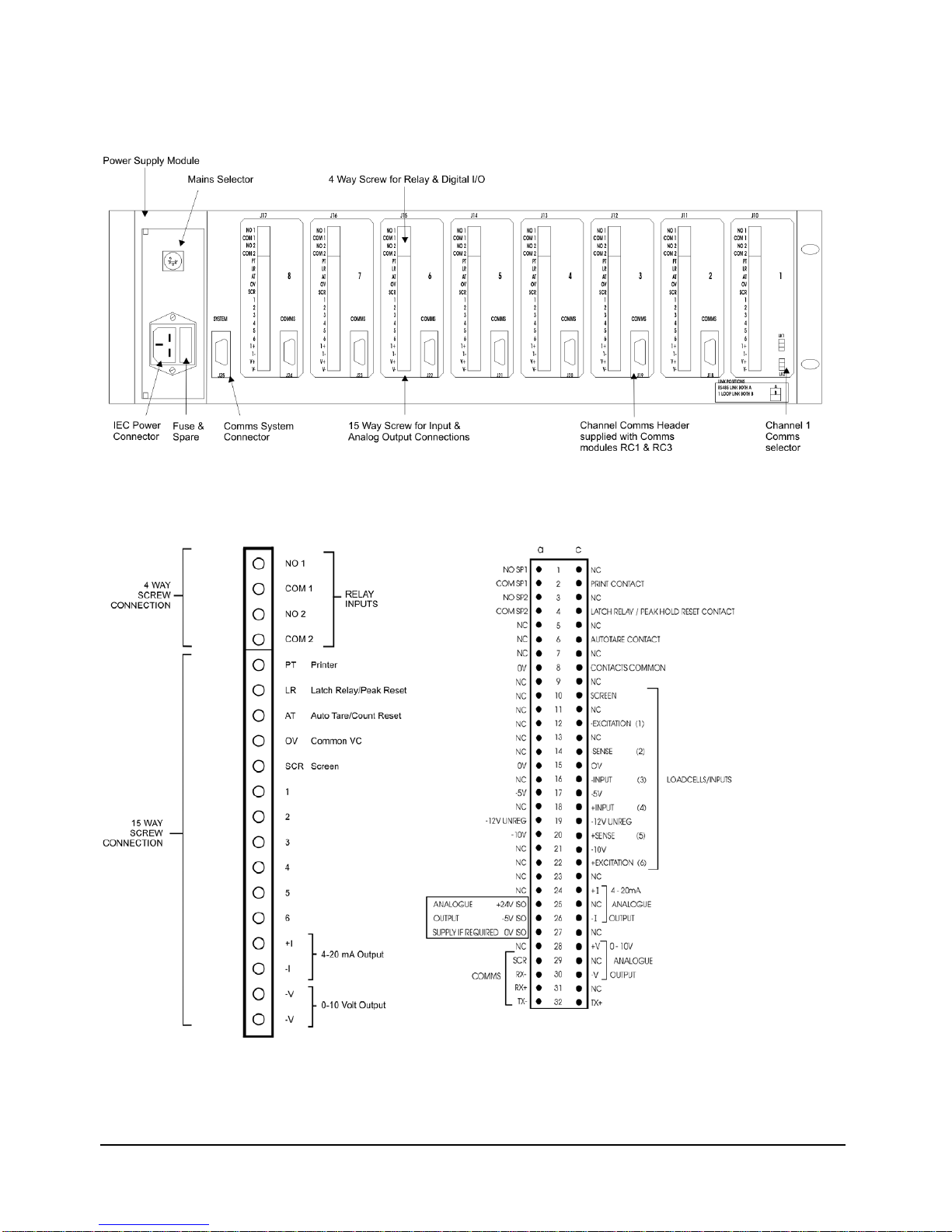
Section 1 -The Rack (RUA) Variant
Figure 2.1 - Rear view of Rack (RUA2)
Figure 2.2 UAB Rear Connection
Terminals Figure 2.3 The 32 Way A & C
(DIN41612) Connections

Mantracourt Electronics Limited UAB User Manual
8
Figure 2.4 Rack Module Layout
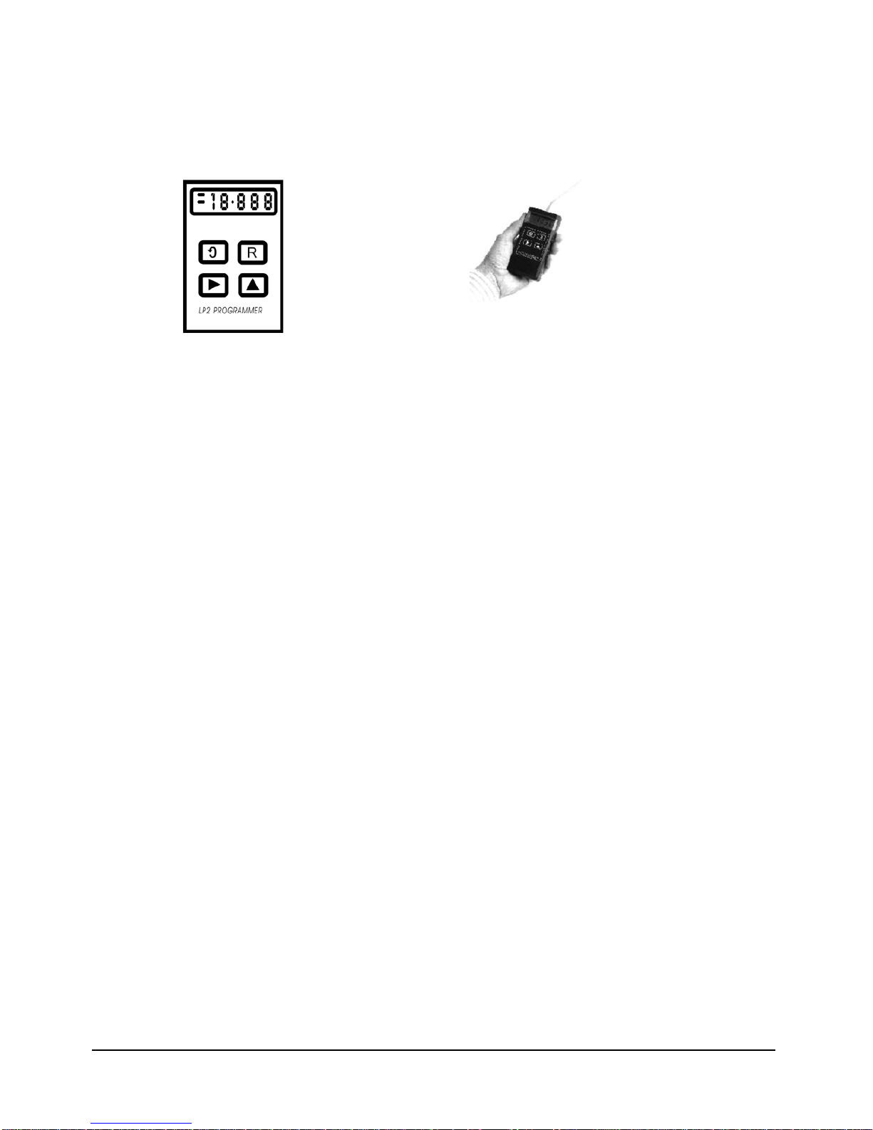
Figure 2.5 LP2 Hand
Held Programming Unit Figure 2.6 RUA1 for
External Programmer
(LP2)
Figure 2.7 RUA2 On-Board
Programmer
Section 2 - The Surface Mount (SMP) Variant
The surface mount variant of the Universal Amplifier is offered in a number of different configurations dependant
upon the system installation requirements, to which any of the input, output and communications modules can be
fitted as described in the diagram in Section 1. Each description is followed by the order coding for ease of
identification.
1.The surface mount IP65 ABS cased version with a large LCD display and programming module mounted in the lid,
where local programming and control is required. - (SMP/C).
2.The DIN rail mounted version with a remotely connected large LCD display and programming module fitted with a
stainless steel panel mounting fixture which will operate up to 2 metres from the amplifier. (SMP/D) A version of
the (SMP/D) above is offered with a driver package (LCDR) where there is a requirement for the remote display
and programming module to operate over distances greater than 2 metres, and up to 100 metres from the
amplifier. Where order codes are required for individual items, please refer to the order code list in the rear of
the manual at Chapter 8.
3.ABS Cased Versions are available without a display and programming module mounted on the lid. Programmed
through the internal FCC socket on the UAB, (using an LP2 Hand Held Programmer see Figure 2.13) or the remote
LP1 On Board Programmer see Figure 2.14

Mantracourt Electronics Limited UAB User Manual
9
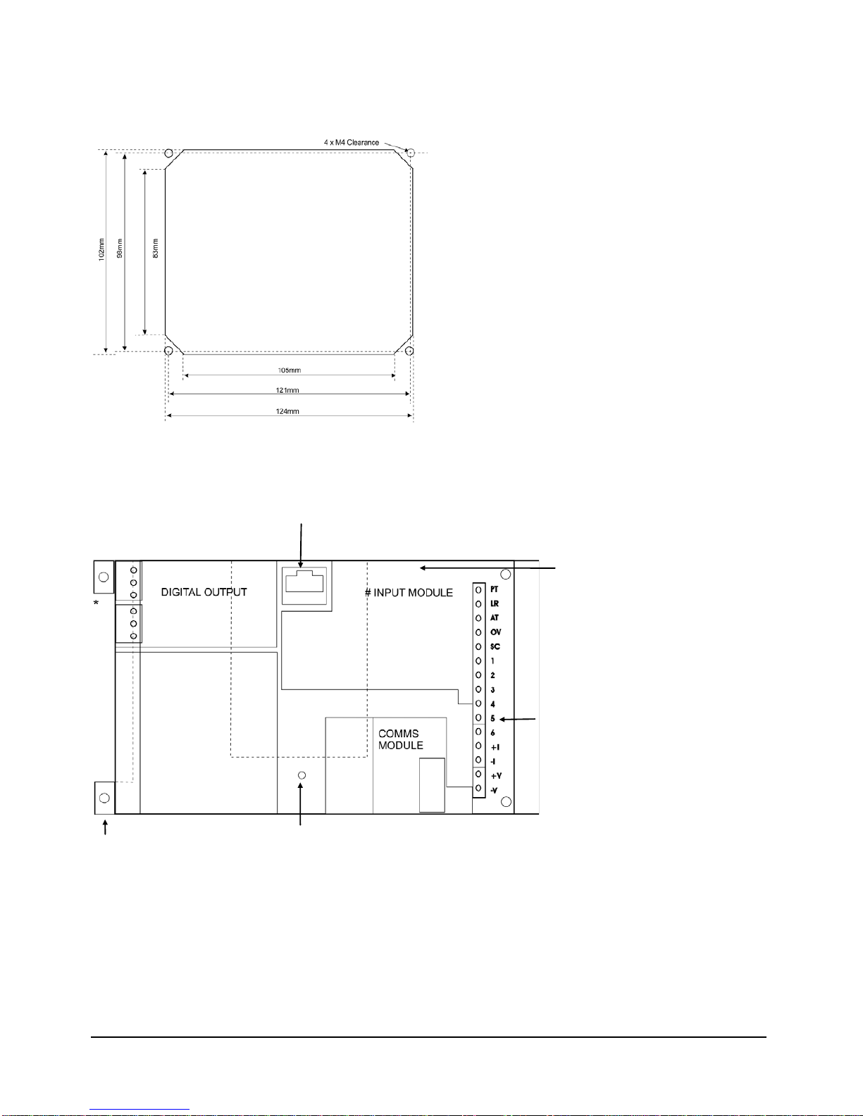
Figure 2.8 The IP65-ABS Case (LAB) Dimensions & Mounting Points
Case Depth = 75mm
Figure 2.9 The DIN Rail Mounting (D2) Dimensions
Max height above
DIN Rail Mounting
surface = 100mm.
Fits ALL carrier rails
DIN/EN 35
Figure 2.10 Stainless Steel Panel Mount & Programming Display
Module, Dimensions & Mounting Points
4mm M4 studs x 12mm for mounting. Sealing is provided by a Neoprene gasket
For LCD max cable length = 2 meters. For LCDR max cable length = 100 meters
Mantracourt Electronics Limited UAB User Manual
10
Figure 2.11 LCS Stainless Steel Panel Cut Out
Where there is a requirement for the stainless steel fixture to be mounted in a panel please note the details of the
‘Cut Out’ are as described in the following drawing.
Figure 2.12 Connection & Fitting Details for the Surface Mounted
Amplifier (UAB)
Display & Keypad FCC68 Connector (For Surface Mounted Display or Hand
Held Programmer LP2 for Non Display Versions.)
The standard
(100mS) strain
gauge input is
contained within
the LCB module &
therefore has no
separate input
module
15 Way field screw
connection for
input, contacts &
AN-OP
For DIN mounting cut off
PCB on white line
WATCHDOG LED
Mantracourt Electronics Limited UAB User Manual
11
Programmers for Surface Mount Variants
Figure 2.13 LP1 On-Board
Programmer Unit
Figure 2.14 LP2 Remote hand Held
Programmer Unit (UAB)

Mantracourt Electronics Limited UAB User Manual
12
Chapter 3 Power Supplies
There are three types of power supply available within the UAB system. The rack versions RUA1 and RUA2 are served
by a common power supply, which offers power to the 12 channels in the case of the RUA1 and 8 channels for the
RUA2. The Surface Mount versions are offered with mains an AC version or a low voltage DC version.
Section 1 - The Rack Version (RS1)
The RS1 supplies power to the channels within the rack via the common back plane, offering 220/240VAC at 50/60
Hz or 110VAC at 50/60 Hz. The 110/240 is selected by a switch on the rear of the power supply module. A green LED
on the front panel indicates when power is applied
A 5-Ampere protection fuse is fitted within the power input socket.
The maximum power rating for a full rack is 100 Watts.
Connection to the rack is made via a flying lead with a shrouded and earthed IEC mains connector
Note: Inputs are not intended to be connected to voltages above 50 VAC or 120Vdc
Tables 3.1 and 3.2 show details of the connections and voltages for the various supply rails.
Table 3.1
SUPPLY CONNECTION
TO DIN 41612
MIN V MAX V MAX ac V CURRENT
per channel
COMMENTS
0V 15a, 15c - - - - Common for
processor supplies
-5V 17a, 17c -4.80 -5.2 1mV 110Ma Power supply
-14V
UNREG
19a, 19c
-11
-18V
150mV
2mA
Used to detect power
fail
-9V8 20a, 20c -9.1 -10.2 1mA 200mA Provides excitation
for stain gauges and
relays
Table 3.2
SUPPLY
CONNECTION
TO DIN 41612
MIN V
MAX V
MAX ac V
CURRENT
per channel
COMMENTS
+24V ISO
25a
+20
+32
240mV
32mA
Only required if AN-
OP to be used
-5V ISO
26a
-4.75
-5.25
1mV
5mA
Only required if AN-
OP to be used
0V ISO
27a
-
-
-
-
Only required if AN-
OP to be used
Section 2 - The Surface Mount Versions (LS1 and LS3)
The LS1 power supply is a ‘plug in’ module supplying 110 Volts AC at 50/60 Hz or 220/240 Volts AC at 50/60 Hz.
A maximum power rating of 10 Watts is available, with this module.
The running current for each amplifier is between 250 and 480 milliamps dependant upon module configuration,
with a start up current of 3 Amps for 20 milliseconds. Earthing (or shield)- If the amplifier is not earthed elsewhere,
an earth should be made to the screen (SC) of the 15 way connector.
PROC-
ESSOR
SUPPLIES
ANALOGUE
OUTPUT
ISOLATED
SUPPLY

Mantracourt Electronics Limited UAB User Manual
13
Figure 3.1 Power Supply LS1 Connections
Figure 3.2 LS3 Connections
The LS3 module should be protected on installation by an in line fuse.
The LS3 power supply is a 'plug in' module supplying 9 to 30 Volts DC. Similar in characteristics to the LS1 with
regard to power and current ratings.
The module is not reverse polarity protected and will require similar protection at installation.
Mantracourt Electronics Limited UAB User Manual
14
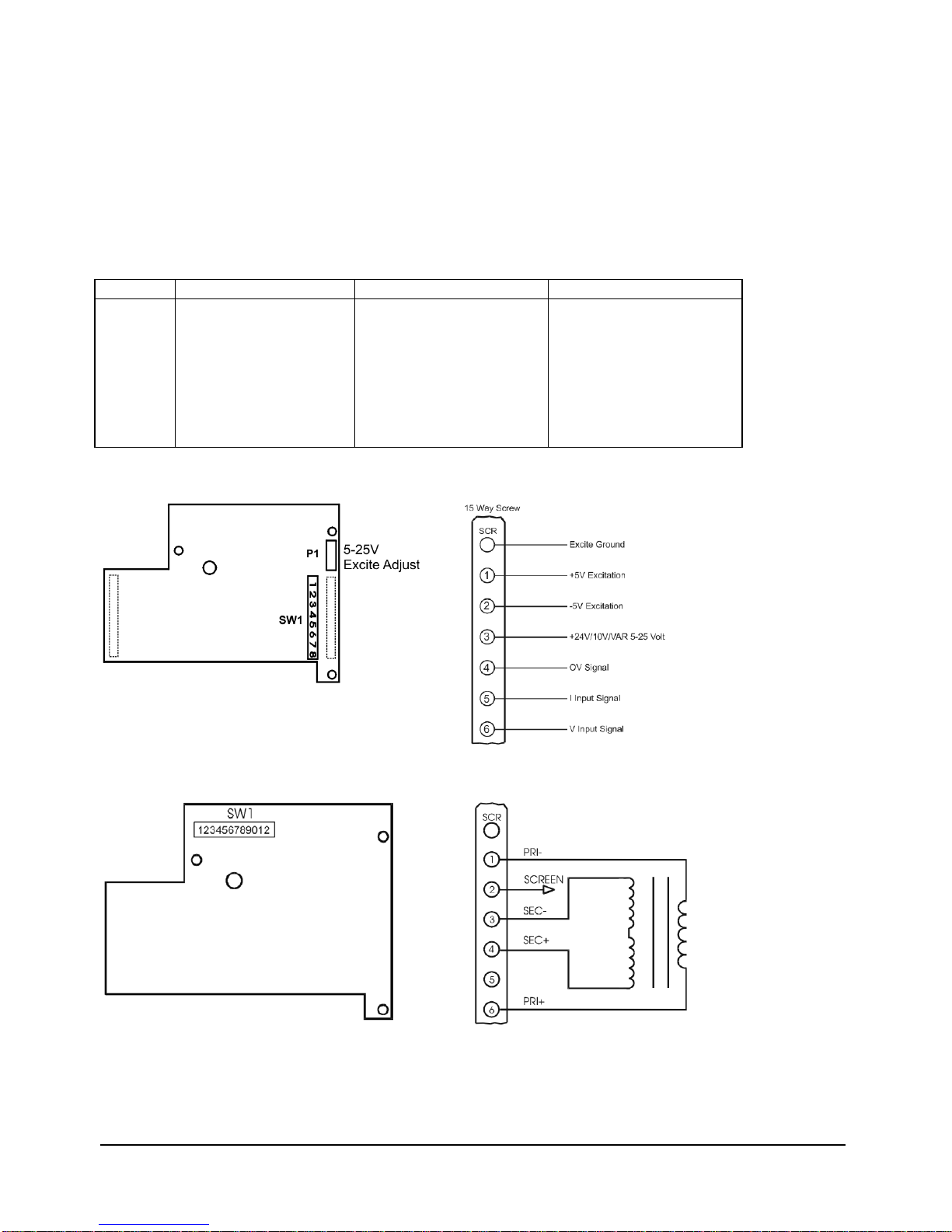
Chapter 4 Input Modules
The following DC Voltage & Current input modules are available:
-
UADCV1 -
UADCA1 -
UADCV2 -
UADIA -
UADIV -
0 to 10 Volts
0 to 20mA
± 200mV
Dual Input - 4 to 20mA
Dual Input - 0 to 10 Volts
Table 4.1 UADCV1 and UADCA1 Switch Configuration
SW1
±200mV
0-10V
0-20mA
1
2
3
4
5
6
7
8
10V Excite
24V Excite
5-25V VAR Excite
ON
OFF
OFF
OFF
OFF
10V Excite
24V Excite
5-25V VAR Excite
OFF
ON
ON
OFF
ON
10V Excite
24V Excite
5-25V VAR Excite
OFF
ON
ON
ON
OFF
Figure 4.1 The UADC1 & UADCA1 Modules
Figure 4.2 The UALV1 - LVDT Module Rear Panel Connections
Mantracourt Electronics Limited UAB User Manual
15
Figure 4.3 LVDT Switch Settings
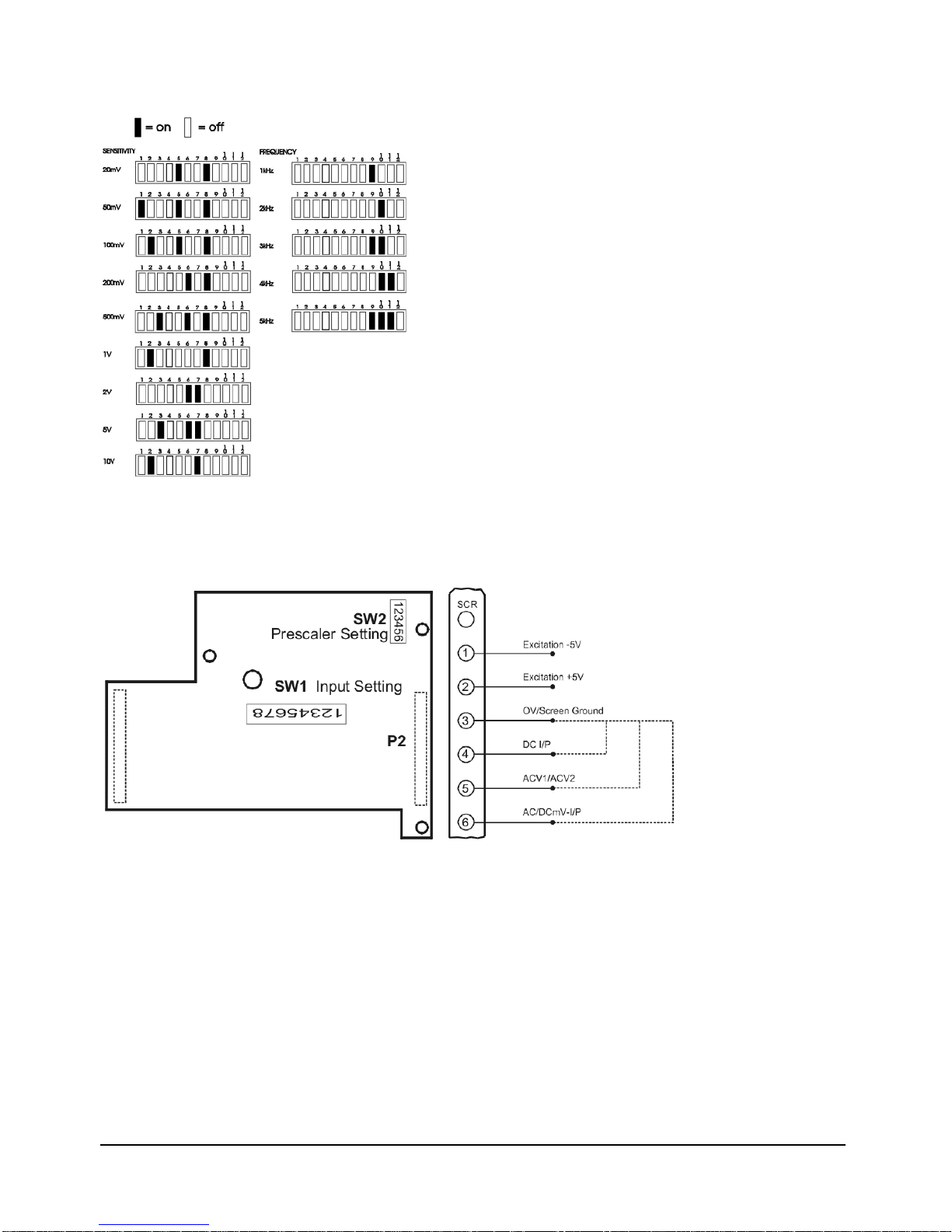
The UARTL - Rate/Totaliser Module
Figure 4.4 Rear Panel Connections
Note: See Chapter 7 Section 4 for details of input and pre scaler settings.
UAT1 -
UAT2 -
Thermocouple Type K Modules
Thermocouple Type J Modules
Connecting the Thermocouple
WARNING:
ENSURE POWER IS SWITCHED OFF BEFORE MAKING CONNECTION TO THE UAB
1. Connect the thermocouple to the UAB terminal as shown in Figure 4.6
Note: If the thermocouple has a floating input, connect terminal 1 to ground.
2. The external cold junction sensor is always connected between input terminals 4 and 6. If no external sensor is
used, link terminals 4 & 6.

Mantracourt Electronics Limited UAB User Manual
16
3. Normally, thermocouple burnout is indicated by upscale over range. If downscale indication is required, link
terminals 2 & 3.
Figure 4.5 UAT1 & 2
Figure 4.6 Thermocouple Connectors
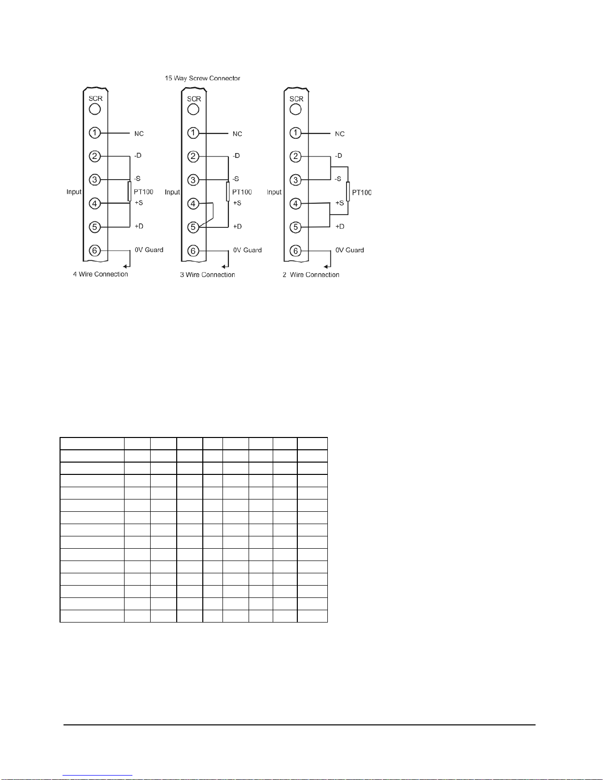
The UAPT Connecting the Resistance Thermometer Module
Connect the resistance thermometer to the UAB terminals as shown in Figure 4.8 using the terminals appropriate to
2, 3 and 4 wire connections.
Note: It is recommended that 4 core-screened cable be used for this connection with terminal 6 used for screen and
ground.
If however, this is not practical, terminal 2 may be used for guard and ground.
Figure 4.7 RTD Module UAPT
Mantracourt Electronics Limited UAB User Manual
17
Figure 4.8 RTD Connections
UAFLC Fast Strain Gauge
The UAFLC offers a direct connection to most low level (foil) strain gauge sensors.
A 10-volt excitation is provided and it is monitored to compensate for any variation due to supply drift, load
regulation or voltage drop in the cable between the sensor and the UAFLC.
The maximum supply current is 150mA, which allows for the connection of 4 x 350 Ohm strain gauges.
Strain gauge sensitivity is preset via DIL switches to 0.5, 0.8, 1.0, 1.25, 1.5, 2.0, 2.5, 3.5, 5, 10, 20, 50, 100 and 200
mV/V. Select the next value higher than the strain gauge output maximum.
Note: It is important that the UAFLC is powered up with the strain gauge connected to the input as the A/D
performs an Autocal of its own on power up.
SW1 mV/V
1
2
3
4
5
6
7
8
0.5
x
-
-
x
-
x
x
x
0.8
-
x
x
-
-
x
x
x
1.0
-
x
-
x
-
-
x
-
1.25
-
x
-
-
-
-
-
x
1.5
-
-
x
x
x
-
-
-
2.0
-
-
x
-
x
-
-
x
2.5
-
-
x
-
-
-
-
-
3.5
-
-
-
x
x
-
-
-
5.0
-
-
-
x
-
-
-
x
10.0
-
-
-
-
x
-
-
x
20.0
-
-
-
-
-
x
-
x
50.0
-
-
-
-
-
-
x
x
100.0
-
-
-
-
-
-
-
x
200.0
-
-
-
-
-
-
-
-
x = ON - = OFF
mV/V = ±mV/V nominal full range gain within ±3%
Mantracourt Electronics Limited UAB User Manual
18
Fast Strain Gauge The (UAFLC) Module
Figure 4.9 UAFLC Module Figure 4.10 UAFLC Connections
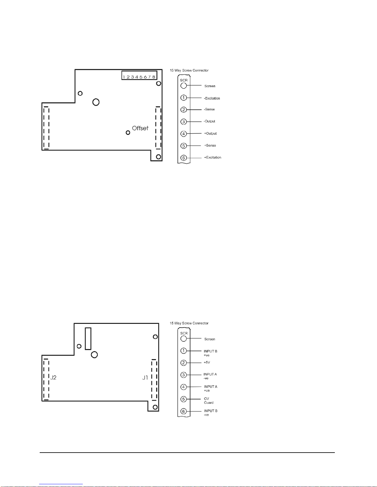
Dual Input Modules
Provide two non-isolated inputs either 4 to 20mA or 0 to 10 volts (This should be specified at time of order) as:
•UADIA = 4/20mA
•UADIV = 0/10 volts
These inputs have independent scaling factors IPLA and IPHA for input 'A' and IPLB and IPHB for input 'B'.
The display can be selected from the list of 'A' and 'B' functions as follows, and can be selected under the mnemonic
'Ab'
0=
1=
2=
3=
4 =
A + B
A - B
A x B
A/B
A = process input, B = setpoint (SP1)
Scale factors can be applied to this function using a scale factor 'SF', a division factor 'DF' and a display offset 'OFFS'.
The analogue output, relays and printer take their value from the function selected at 'Ab’.
Figure 4.11 the UADIA Modules Figure 4.12 UADIA Connections

Mantracourt Electronics Limited UAB User Manual
19
Chapter 5 Output Modules
Section 1 - General Description
Analogue outputs of 4 to 20mAmps and 0 to 10 volts are standard features and an integral part of the Universal
Amplifier pcb.
Further output modules are available offering alarm/control, printer and communications facilities. Analogue
outputs are fully scaleable, opto-isolated and digitally generated.
The analogue output signals are generated by the CPU from the displayed input variable, so that output signals are
normally related to displayed input values except where the PID function is selected. The 4 to 20 mA output is pre
calibrated to an accuracy of within 0.15% of the range. The 0-10V outputs are accurate to within 2% of the 4 to
20mA output.
Notes:
1. Maximum current load on voltage modules is 2mA
2. Maximum drive voltage available in current modules is 20V
The PID function is an option selectable within the standard software program and provides, where required an
analogue output so that outputs are related to the PID power levels and not the displayed input signal.
Note: In this mode the analogue output cannot be scaled.
A fast analogue output module (UAFAO) is available for use with the fast strain gauge (10msec) input (UAFLC),
where a fast capture facility is a requirement.
The digital output modules consist of two single pole change over relays with ON/OFF or PID control. If required,
latching outputs may be selected via the keypad, reset action being achieved by a contact closure or via the
communications module, where a program has been written via an appropriate protocol.
Set points and hysterisis are also set via the keypad or from a communications input.
Relay outputs may also be inverted via the keypad.
Relay operations are controlled by set point and hysterisis values, output inversion, time delays or by the PID time
proportioning output on set point 1.
Figure 5.1 Showing the Potentiometer
for Gain & Offset Adjustment
Figure 5.2 UAFAO Connections
Fast Analogue The (UAFAO) Module
Important Note 1: The output action mnemonic OA must be set to 32 when operating with this module.
Important Note 2: When changing the value of OA to, or from ’32; it is necessary to power the unit off and back on
again as a restart.
See Note with regard to calibrations on Chapter 7 ‘Method of Calculating OPL & OPH from any known output and
Display’
Table of contents
Other Mantracourt Amplifier manuals


