Mantracourt LCI User manual
LCI
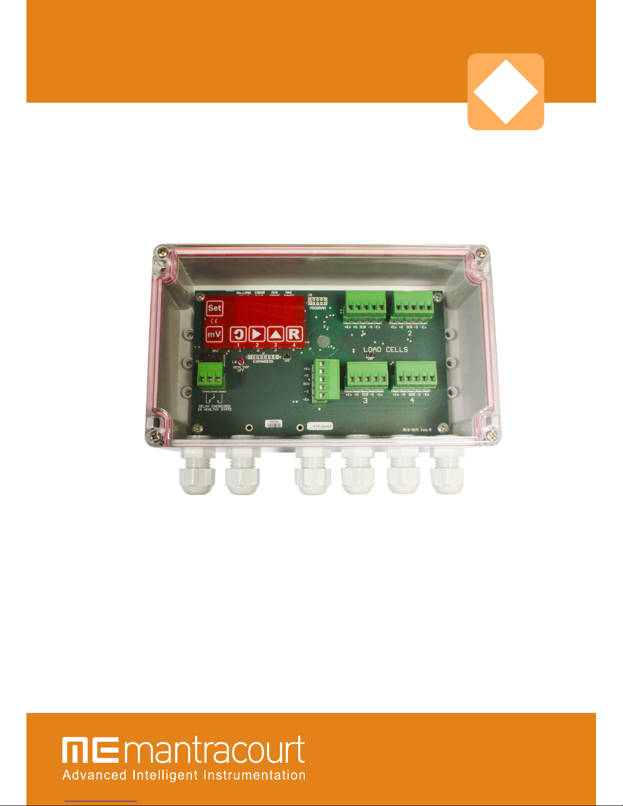
Load Cell Junction Box with Fault Monitor

Mantracourt Electronics Limited LC1 User Manual
1
Contents
Chapter 1 Introduction to the LCI ...................................................................................................... 2
Chapter 2 Installing the LCI.............................................................................................................. 3
Chapter 3 Setting up the LCI ............................................................................................................ 4
Sequence of Operations ................................................................................................................. 4
Chapter 4 Specifications of the LCI ..................................................................................................... 7
Wiring Conditions......................................................................................................................... 8
Warranty.................................................................................................................................... 8

Mantracourt Electronics Limited LC1 User Manual
2
LCI User Manual
Chapter 1 Introduction to the LCI
The LCI, Load Cell Failure Alarm, provides connectivity for 1 to 4 load cells to a Host instrument.
The LCI’s function is to continuously monitor the condition of the individual load cells and set an alarm
condition, by de-energising an on-board relay, if any of the faults listed below are detected.
Continuous detection and diagnosis of fault conditions prevents the incorrect weighing of product and the
subsequent technical and commercial problems resulting from such situations. Any load cell malfunction is
immediately reported by an alarm condition, avoiding incorrect material levels so that there is the
continued assurance of correct product quantities.
The avoidance of batch wastage or product recall, reduction in plant downtime and increased safety,
together with aids for installation and commissioning all contribute to the LCI becoming an essential
element for all weighing systems.
An on-board microprocessor, 4½ digit display and six user switches provide a high level of intelligence
enabling the following features:-
1. Load cell error detection: upon detecting an error, the alarm relay contact activates, the red Alarm LED
illuminates and the display shows the load cell in error and the error code(s) (see chapter 3).
An error is detected if any of the following occur:
One or more of the load cells are out of balance with the pre-set error band
Any load cell is operating outside its pre-set range
The load cell excitation voltage drops
Any of the load cells or its associated cabling become open or short circuit
2. A display of the mV output of each load cell or the average of the summed mV values of all the load
cells.
4V to 12V Version:
The latest version of the LCI (PCB issue 4 onwards) has been re-designed to enable it to operate from an
excitation supply between 4V and 12V without requiring any special set-up procedure or link options.
Host requirements:
The Host must be capable of supplying power to the LCI as well as excitation for the load cells (see Chapter
4 for specifications).
The Host’s excitation supply feeds the load cells via a low voltage-drop reverse polarity protection circuit.
An integral 5V regulator powers the on-board electronics.
The LCI is compatible with Mantracourt’s range of intelligent weighing instruments e.g. ADW15, LCA15,
LCA20, LCD20, SMW etc. as well as suitable third-party products.
Mantracourt Electronics Limited LC1 User Manual
3
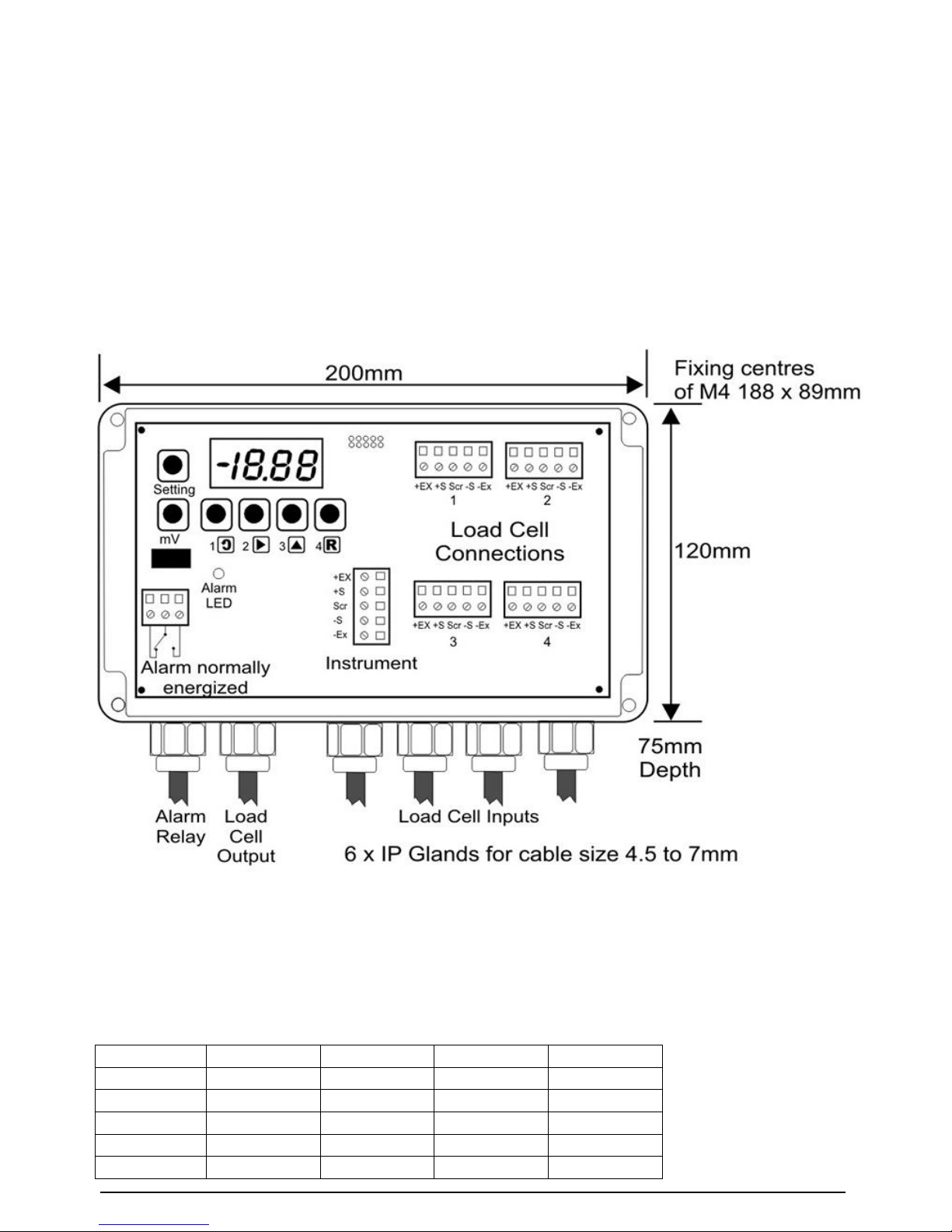
Chapter 2 Installing the LCI
The LCI is supplied as a single PCB unit with four fixing centres to accommodate M4 screws. Case options
are IP65 ABS (as standard), stainless steel, or DIN rail mounting.
Installation of the LCI is simplified by the provision of six two-part plug-in connectors for wiring to the Host,
the load cells and the alarm relay.
Connection details are shown in the diagram below:-
LCI Connection Details
Important Note:
When connecting less than four load cells to the LCI, start at channel one and fill the remaining channels in
numerical order. Set the ‘no C’ parameter accordingly (see table below).
LCI Connections to LCB & ADW15 Details
LCI
LCA20
LCD20
LCB
ADW15
+Ex
+E & +S
+E & +S
+E & +S
5 & 6
+S
+IN
+IN
+IN
4
Scr
SCR
SCR
SCR
1
-S
-IN
-IN
-IN
3
-Ex
-E & -S
-E & -S
-E & -S
1 & 2

Mantracourt Electronics Limited LC1 User Manual
4
Chapter 3 Setting up the LCI
The LCI features a 4-digit red LED display, four programming keys and two function keys.
On ‘Power Up’, the display will show either ‘good’ or display an error code e.g. ‘1Er5’ which, in this case,
would refer to Load Cell 1 with error condition 5.
Sequence of Operations
Programmer Keys
1
Used to scroll through and change the set-up data by displaying
mnemonics for each configurable parameter followed by the appropriate
data and stores the data in non-volatile memory.
2
Selects the display digit to be modified. Selection is indicated by a
flashing digit.
3
Increments each selected display digit 0-9, or –9 to +9 for the most
significant digit depending on whether the ‘-‘ sign is illuminated or not.
4
Saves the current value into non-volatile memory, exits the menu and
resets the display to showing ‘good’ or an error display.
If, during the programming sequence, setting or interrogation is not
completed, the display will revert to the status message after 2 minutes.
Password Protection
A 4 digit password number must be entered. The number is accessed when ‘PASS’ is displayed. At this
point, it is necessary to enter the factory-set number (1111).

Mantracourt Electronics Limited LC1 User Manual
5
Configurable Parameters
Code
Range
Function
1111
Security password
1 to 4
Number of load cells
± 50.00
Load cell operating range Minimum (see 1)
± 50.00
Load Cell operating range Maximum (see 2)
0 to 50.00
Permissible error band between load cells (see 3)
0 to 25.0
Time in seconds before the alarm trips (see 4)
1. This is the lowest operating level (in mV) of any load cell connected. The alarm will activate if
any load cell falls below this value.
2. This is the highest operating level (in mV) of any load cell connected. The alarm will activate
if any load cell exceeds this value.
3. This is the permissible difference (in mV) between any 2 load cells. The alarm will activate if
this value is exceeded.
4. This is the time (in seconds) an error must be present before the error alarm is displayed and
output via the relay.
The Error Displays on the LCI
Note:
On Power Up the display will show either ‘good’ or (‘ ’). Listed below is the range of errors which may
occur, due to fault conditions in the weighing system, load cells or associated wiring.
Display digit 1 shows which load cell is in error. Digits 2 and 3 show an error by displaying ‘ ’. Display digit
4 displays any of five fault conditions as follows:-
Error Condition 1
An open or short circuit on the load cell or connectors
(Check wiring and power supply)
Error Condition 2
The load cell input is open circuit or has exceeded ± 50mV
(Check wiring and power supply)
Error Condition 3
Operating outside the pre-set maximum and minimum range ( & )
(Check wiring, cell mounting, Max /Min operating ranges)
Error Condition 4
The load cell balance has exceeded the pre-set balance band ( )
(Check wiring, cell mounting, error band values)
Error Condition 5
Open circuit of the excitation on the load cell or wiring.
(Check wiring)
Notes:

Mantracourt Electronics Limited LC1 User Manual
6
1. An open or short circuit may cause multiple errors. The display will cycle through multiple errors,
displaying each code for 1 second.
2. To locate faults, start with the load cell, which displays the most errors.
3. The ‘Set’ button automatically steps through the parameters and their values. During this function all
other keys are disabled.
4. The red LED will be off during a healthy state and illuminated if an error occurs.
The alarm relay is energised during a healthy state and drops out if an error occurs (fail safe).
The Millivolt Display readings on the LCI
To view the average of all of the load cell signals, press the ‘mV’ button.
To view the individual load cell signals, hold down the ‘mV’ button and at the same time press and hold
buttons 1 to 4 to select each load cell in turn.

Mantracourt Electronics Limited LC1 User Manual
7
Chapter 4 Specifications of the LCI
Faults Monitored
Load Cell out of pre-set balance range
Load Cell out of pre-set operating range
Low/high excitation
Open circuit of any load cell connection
Short circuit between any load cell connections
Internal load cell fault (bridge imbalance)
Powering
Indication
Setting Method
By Load Cell Excitation from Host
4 digit 7-segment LED display for set up, load cell error type, individual
mV and average mV.
6 buttons for reading & set up
Connections
2 part terminals, up to 2.5mm² cable
4 x 5 way for load cell connection
1 x 5 way for LCI output and power input
1 x 3 way alarm relay contacts
Dimensions
Environmental
Enclosure Material
200 x 120 x 75mm. (PCB dimensions 170 x 100mm excluding mounting
material)
Sealed to IP65 with cable glands & blanking plugs fitted
CE Compliance.
Grey ABS
Parameters
Min
Typical
Max
Units
Power supply voltage (from Host excitation supply)
4
5/10
12
Vdc Note 1
Power supply current (from Host excitation supply)
-
70
80
mA Note 2
Load cell excitation 350R load cell
4
5/10
12
V
Load cell resistance (typically 350-700R)
300
350
1000
Ohm
Load cell sensitivity
1.0
2.0
5.0
mV/V
Number of load cells selectable
1
-
4
Output load (Host input impedance)
1M
-
-
Ohm
Bandwidth (*display only)
-
100
-
Hz
Zero temp. coefficient (*display only) @ 2mV/V @4V
excitation
-
0.008
0.02
%FR/C
Span temperature coefficient (*display only)
-
0.001
0.0025
%/C
Linearity (*display only)
-
-
0.03
%FR
90 day Stability (*display only)
-
-
0.01
%
90 day Stability (*display only)
-
-
0.01
%FR
Operating temperature range
-10
-
85
C
Storage temperature range
-40
-
95
C
Humidity
-
95
-
%
Scan Speed for alarm output (4 cells)
-
40
100
ms
Display range
-50
-
+50
mV
Relay contacts SPCO current (normally energized)
-
-
1
A
Relay contacts SPCO DC voltage (normally energized)
-
-
24
VDC
Relay contacts SPCO AC voltage (normally energized)
-
-
120
VAC
Alarm operating speed for less than 1mV change
-
100
-
ms
mV measurement accuracy individual cell (*display
only)
-
-
±0.1
mV

Mantracourt Electronics Limited LC1 User Manual
8
Note 1: Derived from Host Instrument
Note 2: Excluding load cell excitation current
‘(*display only)’ denotes that the specification applies to the on-board display only, not the Host instrument.
CE Approvals
European EMC Directive
2014/30/EU
BS EN 61326-1:2013
BS EN 61326-2-3:2013
Wiring Conditions
Load Cell and Host cable connections should use individually screened twisted multi-pair cables (e.g. Farnell
118-2117)
Terminate all screens at ‘SCR’. SCR should be connected to a good Earth. The earth connection should be of
sufficient cross sectional area to ensure a low impedance to attenuate RF interference.
Warranty
All LCI products from Mantracourt Electronics Ltd., ('Mantracourt') are warranted against defective material
and workmanship for a period of three (3) years from the date of dispatch.
If the 'Mantracourt' product you purchase appears to have a defect in material or workmanship or fails
during normal use within the period, please contact your Distributor, who will assist you in resolving the
problem. If it is necessary to return the product to 'Mantracourt' please include a note stating name,
company, address, phone number and a detailed description of the problem. Also, please indicate if it is a
warranty repair.
The sender is responsible for shipping charges, freight insurance and proper packaging to prevent breakage
in transit.
'Mantracourt' warranty does not apply to defects resulting from action of the buyer such as mishandling,
improper interfacing, operation outside of design limits, improper repair or unauthorised modification.
No other warranties are expressed or implied. 'Mantracourt' specifically disclaims any implied warranties of
merchantability or fitness for a specific purpose. The remedies outlined above are the buyer’s only
remedies. 'Mantracourt' will not be liable for direct, indirect, special, incidental or consequential damages
whether based on the contract, tort or other legal theory.
Any corrective maintenance required after the warranty period should be performed by 'Mantracourt'
approved personnel only.
In the interests of continued product development, Mantracourt Electronics Limited reserves the right to
alter product specifications without prior notice.

Mantracourt Electronics Limited LC1 User Manual
9
Document Title:
LCI User Manual
Applies To:
LCI
Part Number:
517-164
Issue Number:
1.7
Dated:
22 November 2016
In the interests of continued product development, Mantracourt Electronics
Limited reserves the right to alter product specifications without prior notice.
www.mantracourt.com
Table of contents


