MAPADA M4 UV-VIS User manual

Technical
Manual
M4 UV-VIS Spectrophotometer
TM –202001002
Service Manual
Shanghai MAPADA Instruments Co., Ltd.
Ver: V1.0.0 Date: June 28, 2020


Contents
1 General information.........................................................................................................................................................................1
1.1 Safety Information...................................................................................................................................................................1
1.2 Danger and Warning Information......................................................................................................................................1
1.3 Warning Labels.........................................................................................................................................................................1
2 Overview..............................................................................................................................................................................................3
2.1 Specifications............................................................................................................................................................................3
2.2 Function Diagram....................................................................................................................................................................4
3 Structure..............................................................................................................................................................................................4
4 Optical System...................................................................................................................................................................................8
5 Electronic Control System............................................................................................................................................................10
5.1 Power System .........................................................................................................................................................................10
5.2 Power Supply..........................................................................................................................................................................10
5.3 Control and Data Processing System..............................................................................................................................11
5.3.1 Main Board.....................................................................................................................................................................13
5.3.2 USB Interposer..............................................................................................................................................................16
5.3.3 Interposer .......................................................................................................................................................................16
5.3.4 Touch Screen.................................................................................................................................................................17
5.3.5 Signal Board...................................................................................................................................................................18
6 Maintenance.....................................................................................................................................................................................18
6.1 Replace Fuse............................................................................................................................................................................19
7 Troubleshooting..............................................................................................................................................................................20
7.1 Initialization and warm-up..................................................................................................................................................20
7.2 Maintenance Mode...............................................................................................................................................................21
7.3 How to confirm initialization failure................................................................................................................................22
7.4 Common faults and Solutions...........................................................................................................................................24
8 Disassembly and replacement of parts ...................................................................................................................................29
8.1 Remove shell...........................................................................................................................................................................29
8.2 Remove bottom plate ..........................................................................................................................................................31
8.3 Remove LCD Module............................................................................................................................................................31

8.4 Remove monochromator cover........................................................................................................................................32
8.5 Replace 1# Reflector Mirror...............................................................................................................................................33
8.6 Replace 2# Reflector Mirror...............................................................................................................................................34
8.7 Replace 3# Reflector Mirror...............................................................................................................................................36
8.8 Replace Grating......................................................................................................................................................................38
8.9 Replace Filter Wheel.............................................................................................................................................................39
8.10 Replace Beam splitter...........................................................................................................................................................40
8.11 Replace Signal Board Block................................................................................................................................................41
8.12 Replace Grating Motor ........................................................................................................................................................42
8.13 Replace Filter Wheel Motor................................................................................................................................................43
9 Spare Part List..................................................................................................................................................................................45

1
1General information
1.1 Safety Information
This manual is used by technicians identified by MAPADA to troubleshoot M4 UV-VIS
Spectrophotometers.
Please read this manual in its entirety and pay attention to all danger and warning
instructions. Failure to do so may result in serious personal injury or equipment damage.
Please carry this manual with you and read it carefully before maintenance and repair work.
1.2 Danger and Warning Information
Danger: Indicates a potentially or urgently hazardous situation that, if not avoided,
may result in death or serious personal injury.
Warning: Indicates a potentially hazardous situation that may result in minor or
moderate injury.
Important: Information that requires special attention.
Note: Supplement to the text.
1.3 Warning Labels
Read all the labels and tags attached to the instrument. Failure to do so may result in
personal injury or equipment damage. Any label or tag on the instrument is included in
the manual with danger or warning instructions.
2
Warning Danger!
Warning High voltage!
Warning Hot!
Recycle This instrument will be called back by the designated electrical equipment
processing department or by the original manufacturer when wasted.
Table 1-1 Warning labels

3
2Overview
2.1 Specifications
Model
M4
Optical system
Split beam,1200 l/mm grating
Light source
Flashing xenon lamp
Detector
Dual silicon photodiodes
Spectral bandwidth
2nm
Wavelength range
190~1100 nm
Wavelength accuracy
±0.5 nm
Wavelength Repeatability
≤0.3 nm
Wavelength resolution
0.1 nm
Wavelength selection
Automatic
Wavelength calibration
Automatic calibration after power on
Photometric range
-0.3~3 A, 0~200 %T, 0~9999.9 C
Photometric accuracy
±0.004 A(0~0.5 A), ±0.008 A(0.5~1 A), ±0.5 %T(0~100 %T)
Photometric Repeatability
±0.002 A(0~0.5 A), ±0.004 A(0.5~1 A), ±0.2 %T(0~100 %T)
Stray light
≤0.08 %T
Noise
≤0.001 A @ 0 A, 500 nm, ≤0.002 A @ 1 A, 500 nm, ≤0.004 A @ 2 A, 500
nm
Sample cell holder
10 mm automatic 4-cell holder
Display
5 inch TFT color touch screen
Storage
236 KB (built-in), unlimited expansion (USB storage)
Output
RS232 Serial port ×1 (printer), USB-A×1(USB storage), USB-B×1
(Computer)
Power
100~240 V AC,50~60 Hz,75 W
Dimensions
456(W)×360(D)×185(H)mm
Weight
10.5 kg
Table 2-1 Main specifications

4
2.2 Function Diagram
The function diagram of M4 UV-VIS Spectrophotometer is shown in Figure 2-1. The
control and data processing unit of the instrument receives instructions from the user
(input by touch or PC), controls the operation of each part, reads and processes the signal
and output the measurement results.
Monoch
romator Sample Detector ADC
Measuring
channel
Light
Source
Flashing
Xenon lamp
Control and data processing
Touch screen Serial micro
printer
Personal
computer
USB printer
/ storage
I/O I/O I/O
USB-AUSB-BSerial port(RS232)Serial port(TTL)
Detector ADC
Monitoring
channel
I/O
Figure 2-1 Function diagram
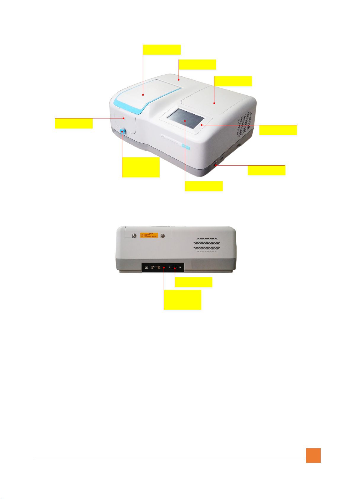
3Structure
The structure and replaceable parts of M4 UV-VIS spectrophotometer are shown in Figure
3-1~3-9.
5
Sample room cover
830415
Housing
830401
Lamp room cover
830423
Display frame
830426
Power button
820201
Sample Room baffle
830424
Rod head
830445
Rod
830437
Touch screen
850101
Figure 3-1 Instrument exterior
Fuse seat
820701
FUSe
820601
IEC Power Inlet
820101
Figure 3-2 Instrument back
6
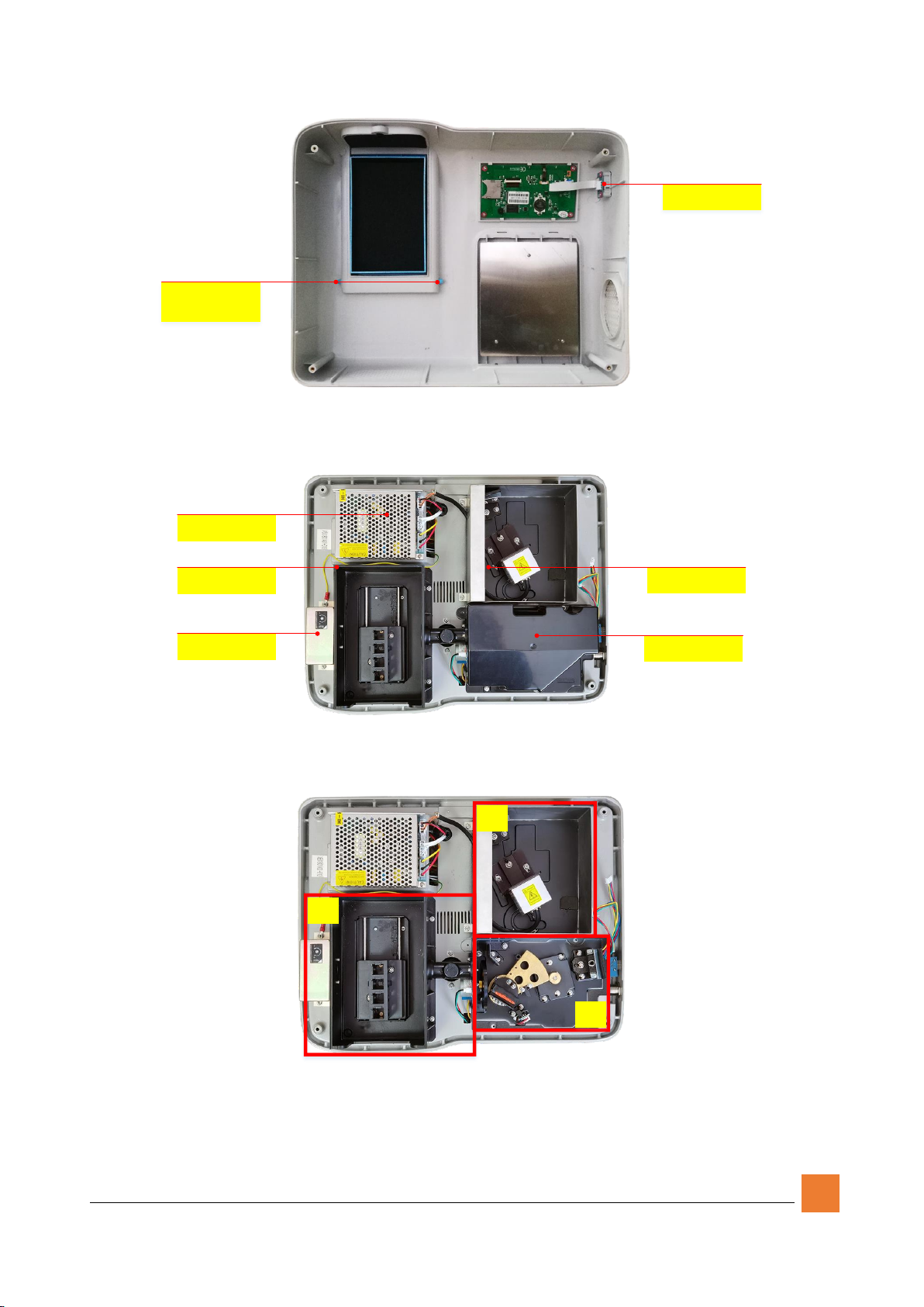
Transit board
860501
Sample Room cover
shaft
830429
Figure 3-3 Shell interior
Monochromator cover
830454
Sample room frame
830458
Amplifier shield
830462
Main power supply
820302
Lamp room frame
830450
Figure 3-4 Instrument interior
A
B
C
Figure 3-5 Internal functional areas

7
Flashing Xenon Lamp
840301
1# Reflector
810103
A
Figure 3-6 Lamp room
3# Reflector
810301
Grating component
810502
2# Reflector
810201
Grating photoelectric
switch
860302
Filter wheel
810602
Filter Wheel motor
820503
Filter Wheel
photoelectric switch
860301
B
Figure 3-7 Monochromator

8
Signal Board(Main)
860212
Len s Seat
810802
10mm 4-Cells sample holder
720101
C
Beamsplitter
810902
Figure 3-8 Sample room and detector
Signal Board(Reference)
860212
USB interface board
860401
Mainboard
860101
Grating motor
820501
Machine foot
830467
Figure 3-9 Instrument bottom
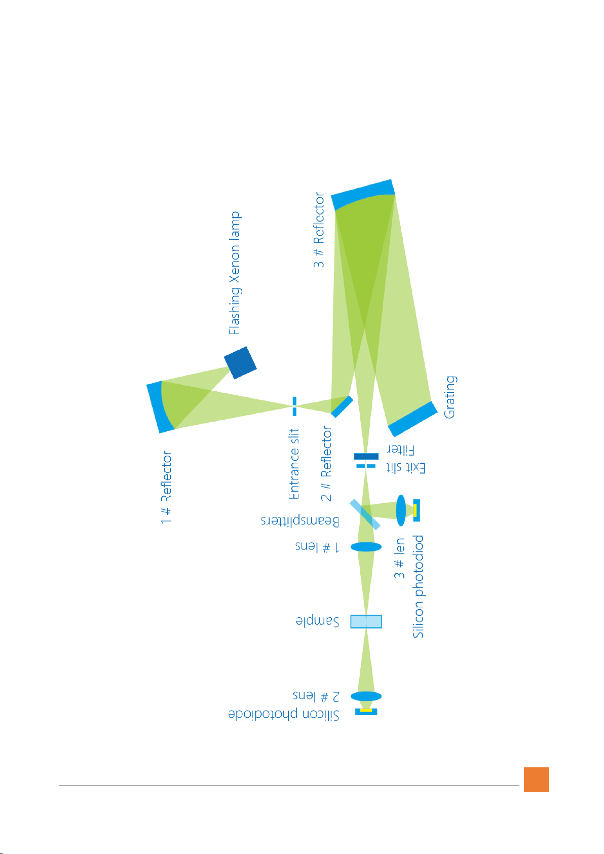
4Optical System
The Optical system of M4 UV-VIS Spectrophotometer is shown in Figure 4-1.
The polychromatic light, emitted by the xenon lamp, passes through 1# Reflector Mirror,
the entrance slit, 2# Reflector Mirror, 3# Reflector Mirror and arrives at the grating. The
9
monochromatic light selected by grating scattering passes through 3# Reflector Mirror,
the filter, exit slit, and splits into 2 beams by the beam splitter. One beam passes through
1# Lens, the sample cell, 2# Lens and arrives at the detector to form the measuring path,
which is used to measure the samples. The other beam passes through 3# Lens and arrives
at the detector to form the monitoring path, which is used to monitor light source change
and improve stability.
Figure 4-1 Optical system

10
5Electronic Control System
The electronic control system of M4 UV-VIS Spectrophotometer consists of 3 modules:
power system, control and data processing system and signal processing system.
5.1 Power System
M4 UV-VIS Spectrophotometer uses AC 100~240V, 50/60Hz. The power passes through
the power socket with a EMI filter, the fuse, the power switch, and then connects to the
switch power supply (Figure 5-1).
Main power supply
PG
L
N
Cable
821011
Cable
821009
Cable
821010
Cable
821013
IEC power
Inlet Fuse
Power switch
Figure 5-1 Instrument power
5.2 Power Supply
The power supply provides power for all the modules and receives signals from the main
board to control the on/off of the xenon lamp.
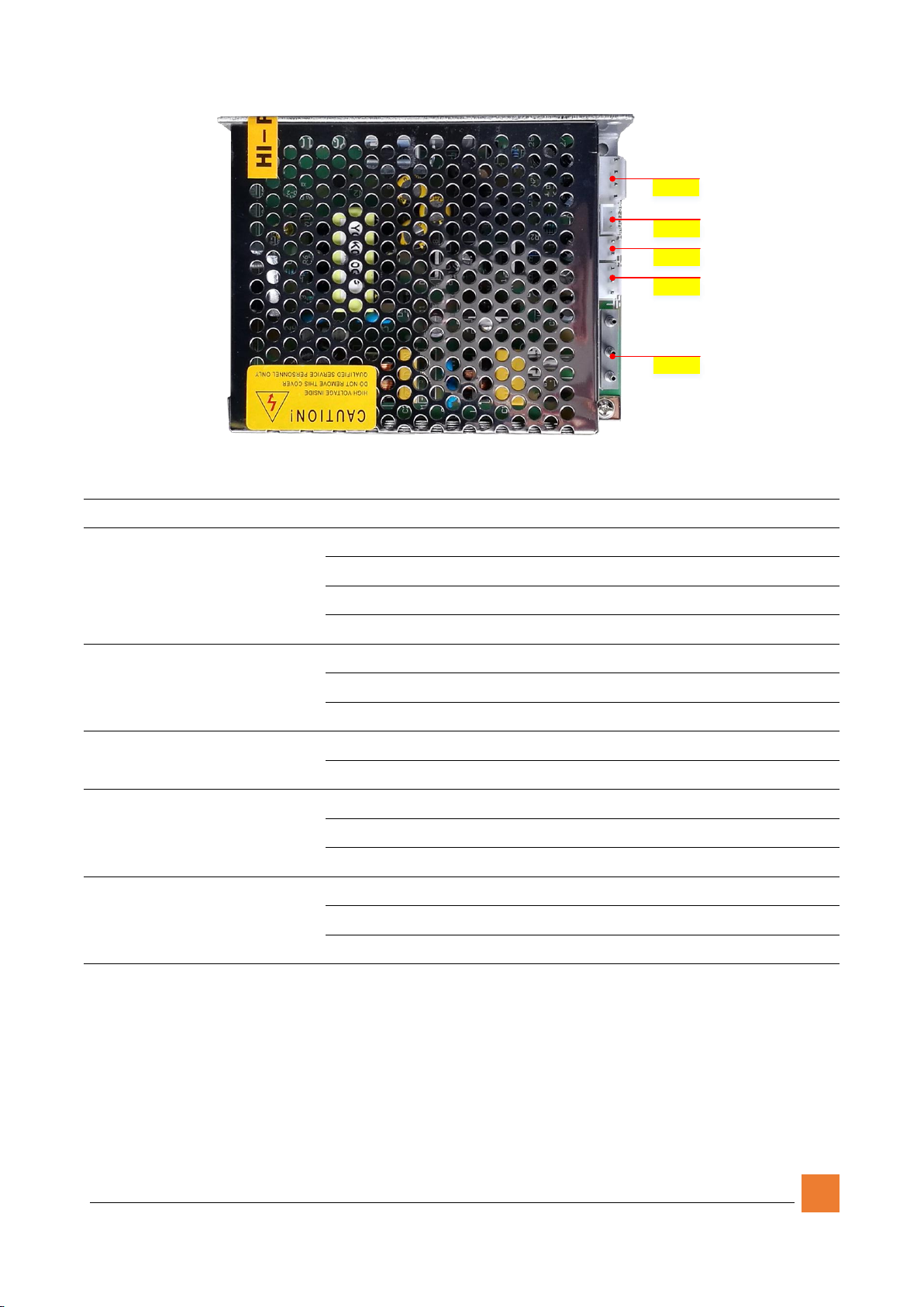
11
J1
J2
J3
J4
J5
Figure 5-2 Instrument main power
Number
Description
Pin
Pin definition
J1
Motor power +
xenon power
1
+12V
2
GND
3
+11.7V
4
GND
J2
Xenon switch input
1
Unused
2
V+
3
V-
J3
System power
1
+5V
2
GND
J4
Amplifying circuit
power
1
+12V
2
GND
3
-12V
J5
AC input
1
PG
2
N
3
L
Table 5-1 Universal power description
5.3 Control and Data Processing System
The control and data processing system of M4 UV-VIS Spectrophotometer is the core
of the instrument. The control unit receives instruction from users (input by touch or PC
through USB), controls operation of all modules, reads and processes measurement

12
signals, and outputs measurement results.
Main power supply
Mainboard
Flashing Xenon Lamp
Auuto sample holder
Filter wheel motor
Grating motor
Filter Wheel
photoelectric switch
Grating photoelectric
switch
Reference Signal Board
USB interface board
Touch screen
Transit board
Cable
821022
Cable
821021
Cable
821024
Cable
821023
Cable
821019
Cable
821017
Cable
821018
Cable
821016
J211
J208
J200
J202
J206
J218
J215
J216
Main Signalboard
Cable
821020 J201
J207
J212
J220
J214
J221
Cable
821025
Cable
821026
Figure 5-3 Control system diagram

13
5.3.1 Main Board
J216
J218
J201
J215
J211
J212
J214
J208
J202
J220
J219
J210
J203
J206
J200
Figure 5-4 Main board
Number
Description
Pin
Pin definition
J200,J201
Signal board
interface
1, 2
GND, digital ground
3
Integrator charging switch

14
4
Integrator reset
5 –7,14
Integrator charging capacitance selection
11
ADC chip select, active low
12
ADC clock
13
ADC data
15,16
+15V, simulate part power+
17,18
SGND, simulate part earthing
19,20
-15V, simulate part power-
J202
Touch screen
interface
1
+5V
2
RXD,serial port reception (TTL)
3
TXD,serial port sending(TTL)
4
GND
J203
Serial printer
interface
1,4,7 - 9
Unused
2
TXD, serial port sending (RS232)
3
RXD, serial port reception (RS232)
5
GND
6
DSR, printer idle signal
J206
Xenon lamp switch
signal output
1
V+
2
V-
J207
Deuterium lamp
switch signal output
1
V+
2
V-
J208
USB adapter board
interface
1,2
+5V
3
USB D-
4
USB D+
5,6
GND
J210
USB-B
1
VBUS
2
USB D-
3
USB D+
4
GND
J211
Auto cell holder
interface
1
+5V
2
Initial positioning photoelectric switch signal output, active
high
3,4
GND
5,6
+12V
7,8
PA, stepper motor phase A
9,10
PB, stepper motor phase B

15
11,12
PC, stepper motor phase C
13,14
PD, stepper motor phase D
15
Auto sample holder detection signal, active low
16
Unused
J212
Filter wheel motor
interface
1
+12V
2
PA, stepper motor phase A
3
PB, stepper motor phase B
4
PC, stepper motor phase C
5
PD, stepper motor phase D
J213
Light switch mirror
interface
1,2
+12V
3
PA, stepper motor phase A
4
PB, stepper motor phase B
5
PC, stepper motor phase C
6
PD, stepper motor phase D
J214
Grating motor
interface
1
PA+, stepper motor A +
2
PA-, stepper motor A -
3
PB+, stepper motor B+
5
PB-, stepper motor B-
J215
Motor power
1
+12V
2
Unused
3
GND
J216
System power
1
+5V
2
GND
J217
Fan power
1
+12V
2
GND
J218
Signal power
1
+12V
2
SGND
3
-12V
J219
Wavelength
photoelectric switch
interface
1
+5V
2
Signal input, high level positioning
3
GND
J220
Filter wheel
photoelectric switch
interface
1
+5V
2
Signal input, high level positioning
3
GND
J221
Light source switch
limit switch
1
Unused
2
Signal input, low level positioning
16
interface
3
GND
Table 5-3 Main board description
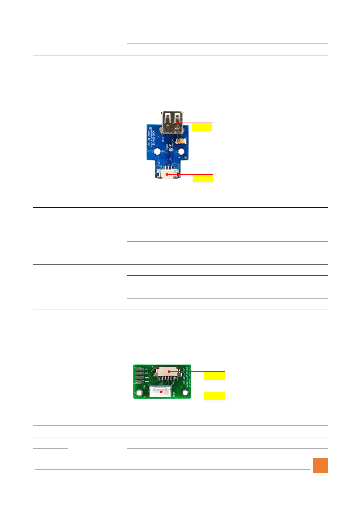
5.3.2 USB Interposer
J401
J400
Figure 5-5 USB Interposer
Number
Description
Pin
Pin definition
J400
USB interposer
interface
1,2
+5V
3
USB D-
4
USB D+
5,6
GND
J401
USB-A
1
VBUS
2
USB D-
3
USB D+
4
GND
Table 5-4 USB interposer description
5.3.3 Interposer
J701
J700
Figure 5-6 Interposer
Number
Description
Pin
Pin definition
J700
Main board
1
+5V
Table of contents
Other MAPADA Medical Equipment manuals


