Maple Armor FW106S,FW106SC User manual

MapleArmor
FW106S,FW106SC
FireAlarmControlPanel
DOC‐FW106S‐UM‐R1.0
InstallationandOperationManual

InstallationandOperationManual
I
TABLEOFCONTENTS
ControlPanelLimitations...................................................................................................................................................1
AgencyListings,Approvals.................................................................................................................................................2
UnderwritersLaboratories(UL/ULC)..........................................................................................................................2
RequirementsforAllInstallations......................................................................................................................2
RequirementsforLocalProtectedFireAlarmSystems......................................................................................2
Overview............................................................................................................................................................................3
FW106S/FW106SCFireAlarmControlPanel..............................................................................................................3
BoardAssemblyDiagram...........................................................................................................................................5
FW106S/FW106SCConfiguration................................................................................................................................6
SpecificationsandFeatures........................................................................................................................................7
SystemComponents...................................................................................................................................................8
ComponentsOverview.......................................................................................................................................8
AMI.....................................................................................................................................................................9
PTU...................................................................................................................................................................10
PCU...................................................................................................................................................................11
ALU...................................................................................................................................................................12
NOU..................................................................................................................................................................13
ROU...................................................................................................................................................................14
XNU...................................................................................................................................................................15
Battery..............................................................................................................................................................15
INSTALLATION...................................................................................................................................................................16
Cautions....................................................................................................................................................................16
ControlPanelLocation.............................................................................................................................................16
ControlPanelInstallationNotice..............................................................................................................................16
FW106S/FW106SCMountingSpace........................................................................................................................17
FW106S/FW106SCInstallationSize..........................................................................................................................18
CabinetMounting.....................................................................................................................................................19
RemoveKnock‐Outs.................................................................................................................................................19
BatteryInstallation...................................................................................................................................................21
UnitAddressSetting.................................................................................................................................................22
SYSTEMWIRING...............................................................................................................................................................23
WiringNotes.............................................................................................................................................................23
PowerLimiting..........................................................................................................................................................23
WiringEnteringtheEnclosure..........................................................................................................................23
WiringSeparation.............................................................................................................................................24
PowerSupplyWiring................................................................................................................................................24
ACConnection..................................................................................................................................................24
BatteryConnection...........................................................................................................................................27
AddressableLoopCircuitWiring..............................................................................................................................28
AddressableLoopCircuitWiring–ClassA.......................................................................................................28
AddressableLoopCircuitWiring–ClassB.......................................................................................................29

InstallationandOperationManual
II
NotificationApplianceCircuitWiring.......................................................................................................................30
NotificationApplianceCircuitWiring–ClassA................................................................................................30
NotificationApplianceCircuitWiring–ClassB................................................................................................31
RelayOutputCircuitWiring......................................................................................................................................32
ExternalNetworkCircuitWiring...............................................................................................................................33
ExternalNetworkCircuitWiring‐ClassB.........................................................................................................33
AuxiliaryPowerOutputWiring.................................................................................................................................34
CommunicationPortConnection.............................................................................................................................34
SystemCheckout......................................................................................................................................................36
BeforeTurningthePowerON...........................................................................................................................36
Power‐upProcedure.........................................................................................................................................36
Troubleshooting........................................................................................................................................................37
CircuitTrouble..................................................................................................................................................37
GroundFault.....................................................................................................................................................37
BatteryTrouble.................................................................................................................................................37
CommonTrouble..............................................................................................................................................37
Operation.........................................................................................................................................................................38
Statushandling.........................................................................................................................................................38
StandbyCondition............................................................................................................................................38
AlarmConditions..............................................................................................................................................38
TroubleConditions...........................................................................................................................................39
SupervisoryConditions.....................................................................................................................................41
Device,ApplianceHandling......................................................................................................................................42
NACActivationandSilence..............................................................................................................................42
DeviceSupervision...........................................................................................................................................42
DetectorMonitor..............................................................................................................................................42
ManualStationResponse..................................................................................................................................43
DriftCompensation..........................................................................................................................................43
AlarmVerification.............................................................................................................................................43
PositiveAlarmSequence(PAS).........................................................................................................................44
Two‐Stage.........................................................................................................................................................45
By‐pass..............................................................................................................................................................45
Autoaddressing................................................................................................................................................45
EventHistory............................................................................................................................................................46
LED,Buzzer,Buttons.................................................................................................................................................47
LEDsOperation.................................................................................................................................................47
BuzzerOperation..............................................................................................................................................48
ButtonOperation..............................................................................................................................................49
LCDDisplay.......................................................................................................................................................50
LampTest..........................................................................................................................................................50
ConfigurationandMaintenance................................................................................................................................51
PCConfiguration...............................................................................................................................................51
ControlPanelAccessControl............................................................................................................................51
ControlPanelConfiguration.............................................................................................................................52
Appendix‐A:CompatibleDevices.....................................................................................................................................57

InstallationandOperationManual
III
DevicesforAddressableLoopCircuits......................................................................................................................57
AppliancesforNotificationApplianceCircuits.........................................................................................................57
Appendix‐B:WireSelectionGuide...................................................................................................................................58
SLCWireSelectionGuide..........................................................................................................................................58
NACWireSelectionGuide........................................................................................................................................59
AnnunciatorWireSelectionGuide............................................................................................................................59
Appendix‐C:QuantitiesofNotificationAppliances..........................................................................................................60
Appendix‐D:BatteryCalculations
.....................................................................................................................................61
Total SystemCurrentsCalculations..........................................................................................................................61
BatteryCapacity.......................................................................................................................................................63
Appendix‐E:GlossaryandAcronyms................................................................................................................................64

InstallationandOperationManual
IV
ListofFigures
Figure1FW106S/FW106SCControlPanel.........................................................................................................................3
Figure2AssemblyDiagram................................................................................................................................................5
Figure3AssemblyDiagram(Inside)...................................................................................................................................5
Figure4AMI(Front)...........................................................................................................................................................9
Figure5AMI(Back)..........................................................................................................................................................10
Figure6PTU.....................................................................................................................................................................10
Figure7PCU.....................................................................................................................................................................11
Figure8ALU.....................................................................................................................................................................12
Figure9NOU....................................................................................................................................................................13
Figure10ROU...................................................................................................................................................................14
Figure11XNU...................................................................................................................................................................15
Figure12FW106S/FW106SCEnclosureMountingSize...................................................................................................17
Figure13FW106S/FW106SCInstallationSize..................................................................................................................18
Figure14WiringSeparation.............................................................................................................................................20
Figure15BatteryInstallation...........................................................................................................................................21
Figure16UnitAddressSwitch..........................................................................................................................................22
Figure17WiringTerminalsLocation................................................................................................................................24
Figure18ACPowerSupplyWiring...................................................................................................................................25
Figure19GroundWiring..................................................................................................................................................25
Figure20ACPowerSupplyWiring(Terminal)..................................................................................................................26
Figure21BatteryConnection...........................................................................................................................................27
Figure22AddressableLoopCircuitWiring–ClassA.......................................................................................................28
Figure23AddressableLoopCircuitWiring–ClassB.......................................................................................................29
Figure24NotificationApplianceCircuitWiring–ClassA................................................................................................30
Figure25NotificationApplianceCircuitWiring–ClassB................................................................................................31
Figure26RelayOutputCircuitWiring..............................................................................................................................32
Figure27ExternalNetworkCircuitWiring‐ClassB.........................................................................................................33
Figure28AuxiliaryPowerOutputWiring.........................................................................................................................34
Figure29AMI...................................................................................................................................................................35
Figure30LCD(Standby)...................................................................................................................................................38
Figure31LCD(Trouble)....................................................................................................................................................39
Figure32AlarmVerification.............................................................................................................................................43
Figure33PositiveAlarmSequence..................................................................................................................................44
Figure34Two‐StageAlarm...............................................................................................................................................45

InstallationandOperationManual
V
ListofTables
Table1FW106S/FW106SCModuleUnits..........................................................................................................................6
Table2FW106S/FW106SCControlPanelSpecifications....................................................................................................7
Table3SystemComponents..............................................................................................................................................8
Table5UnitAddressRange..............................................................................................................................................22
Table6CircuitTrouble......................................................................................................................................................37
Table7TroubleEventType...............................................................................................................................................40
Table8LEDsOperation.....................................................................................................................................................47
Table9ButtonsFunction..................................................................................................................................................49
Table10AccessLevel0Operation...................................................................................................................................52
Table11AccessLevel1Operation...................................................................................................................................52
Table12AccessLevel2Operation...................................................................................................................................52
Table13AccessLevel3Operation...................................................................................................................................53
Table14DeviceforAddressableDeviceCircuits..............................................................................................................57
Table15ApplianceforNotificationApplianceCircuits....................................................................................................57
Table16AddressableLoopWiring...................................................................................................................................58
Table17NACWiringTable...............................................................................................................................................59
Table18AnnunciatorWiringTable..................................................................................................................................59
Table19MaximumNumbersofNA.................................................................................................................................60
Table20SystemCurrentsCalculation..............................................................................................................................61
Table21BatteryCalculation.............................................................................................................................................63

InstallationandOperationManual
1
ControlPanelLimitations
TheFW106S/FW106SCcontrolpanelmaynotshowanalarmconditionwithoutcompatibleinitiating
devices(smokedetectors,etc.)andnotificationdevices(horn,lights,etc.)connectedtoit.Electricalratings
oftheinitiationandnotificationappliancesmustbecompatiblewiththeelectricalratingsofthecontrol
panelandmustbeproperlyinterconnected.Thewiringusedforinterconnectionmustbelargeenoughto
carrythetotalcurrentforallapplianceswithoutexcessivevoltagedrop.PleaserefertoAppendix‐B:Wire
SelectionGuidefordetail.
Thecontrolpanelmustbeconnectedtoadedicatedprimaryelectricalsourcethathasahighdegreeof
reliabilityandadequatecapacityforthiscontrolpanel.Themeansofdisconnectingthispowersourceshallbe
availableonlytoauthorizedpersonnelandclearlymarked"FireAlarmCircuitControl".
Abatteryset(24V)thathasenoughcapacitytoproperlyoperatethesystemfor24hoursstandbyand
30minutesalarmperUL86410thEdition(section69.2.3and69.2.5)/ULC‐S5273rdEdition(section10.5)oras
otherwiserequiredbylocalcodesandtheAHJmustalsobeconnectedtothecontrolpanel.Thesebatteriesdo
losecapacitywithage.Batteriesmustbereplacedwhentheyfailtoprovidethecontrolpanelwiththerequired
standbyandalarmpowerorafter4years,whicheverhappensfirst.Thesebatteriesmustbecheckedfor
performanceatleasttwiceayearormoreoften,iflocalrequirementsdictate.
Eventhoughthiscontrolpanelwasmadetolastfortheexpectedlifeofthefirealarmsystem,partscanfailat
anytime.Therefore,aregulartestprogramshouldbefollowedanddocumentedtomakesureeachpartofthe
systemistested,asindicatedinChapter7ofNFPA72,andCAN/ULC‐S536,ormoreoftenifdictatedbylocal
coderequirements.Malfunctioningunitsmustbereplacedorrepairedimmediatelybyfactoryauthorized
servicepersonnel.
Thiscontrolpanelisdesignedtoshowanalarmconditionwhentheinitiatingdevicesconnectedtoit
detectsspecificconditions.Theseconditionsmayormaynotrepresentalife‐threateningcondition.
Unneededevacuationofabuildingoranareamaysubjectindividualstoanunnecessaryhazard.
Therefore,itisimportantthatthebuildingowner,manager,orrepresentativepromulgate,distribute,
and/orpostinstructionsdescribingstepstobetakenwhenthefirealarmcontrolpanelsignalsan
alarmcondition.Theseinstructionsshouldbedevelopedinco‐operationwithrepresentativesofthe
localauthorityhavingjurisdictionandinaccordancewiththeapplicablestandards.

InstallationandOperationManual
2
AgencyListings,Approvals
UnderwritersLaboratories(UL/ULC)
RequirementsforAllInstallations
Thegeneralrequirementsaredescribedinthissection.Wheninstallinganindividualdevice,refertothe
specificsectionofthemanualforadditionalrequirements.
1.AllfieldwiringmustbeinstalledinaccordancewithNFPA70NationalElectricCode,CSAC22.1Canadian
ElectricalCodePart1,CAN/ULC‐S524,NBC,NBC,NFC,AHJ,andlocalcoderequirements.
2.Usetheaddressablesmokedetectorslistedinthecompatibilitychart(Appendix‐A:CompatibleDevices).
3.UseUL/ULClistednotificationappliancescompatiblewiththeFW106S/FW106SCfromthosespecifiedin
Appendix‐A:CompatibleDevicesofthismanual.
4.Afullsystemverificationmustbeperformedeverytimethepanelisprogrammedorreprogrammed.
RequirementsforLocalProtectedFireAlarmSystems
AtleastoneULlistedsupervisednotificationappliancesmustbeused.

InstallationandOperationManual
3
Overview
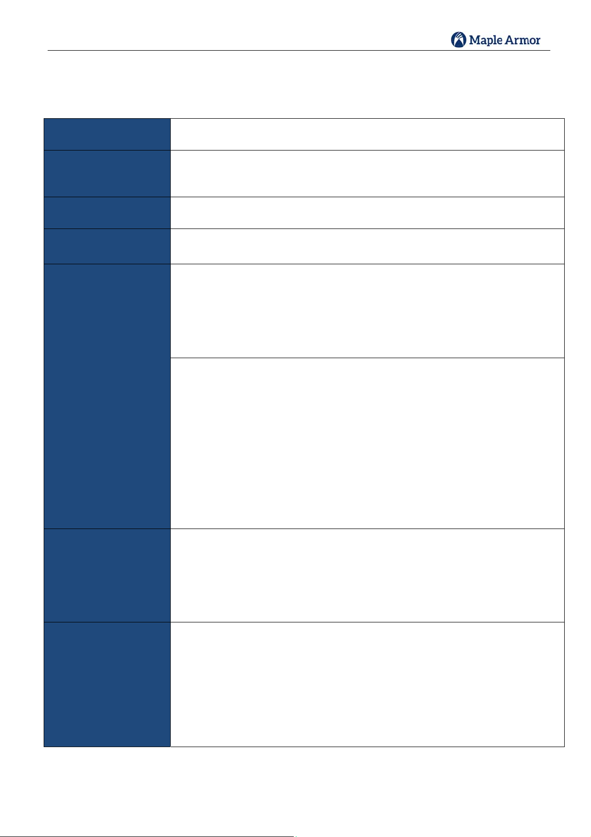
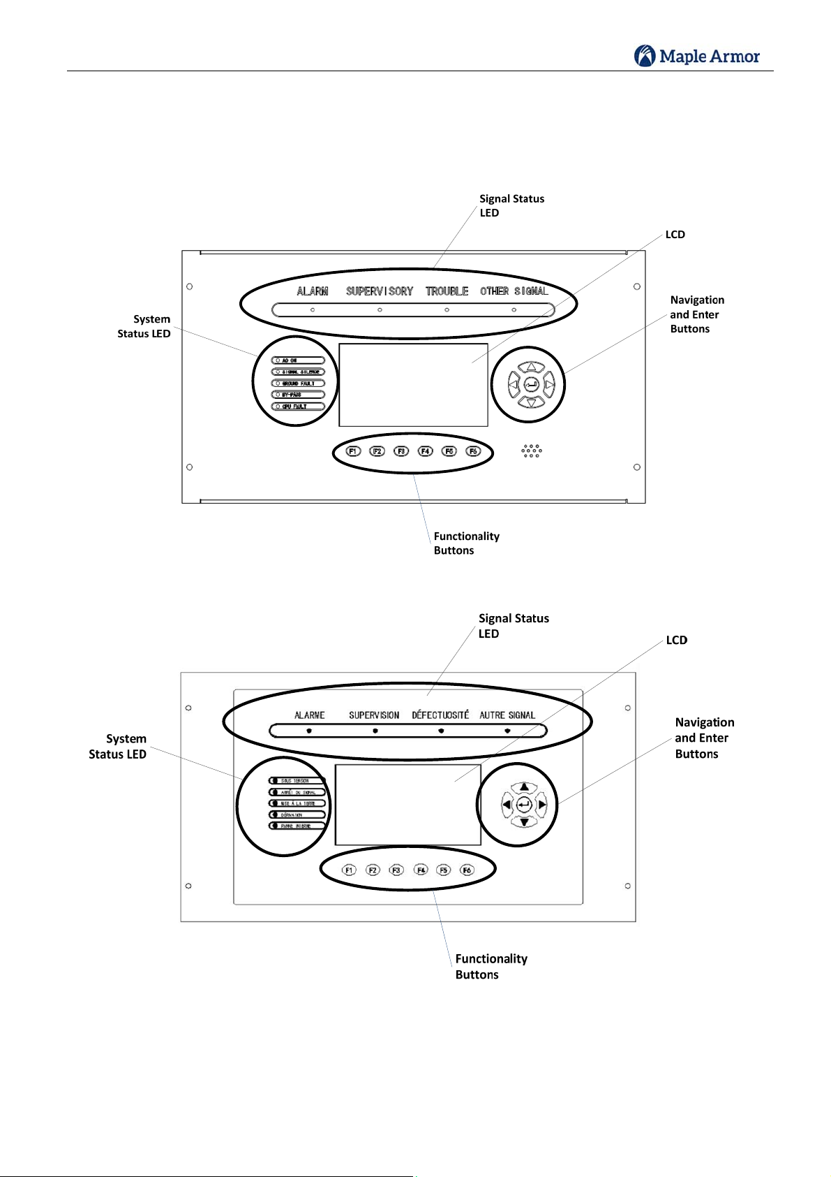
FW106S/FW106SCFireAlarmControlPanel
TheFireWatcherFW106S/FW106SCisanintelligentFireAlarmControlPaneldesignedforsmalltomedium‐scale
facilities.TheFireWatcherFW106S/FW106SCisideallysuitedforbothnewandretrofitcommercial,institutional,
andindustrialfiredetectionandnotificationapplications.TheonlydifferencebetweenFW106SandFW106SCis
thelanguage.FW106SisinEnglishandFW106SCisinFrench.
(a) FW106S(English)(b)FW106SC(French)
Figure1FW106S/FW106SCControlPanel
TheFireWatcherFW106S/FW106SCisanaddressablefirecontrolsystemthatmeetstherequirementsofUL
86410thEdition,andCAN/ULC‐S5273rdedition.Itcansupport:
4AddressableLoopCircuitsand1,008addressabledevices/points
4NotificationApplianceCircuits
5formCdryrelaycontacts.
TheFW106S/FW106SChas
A7”colorLCDandaresolutionof800×480
6auxiliaryfunctionkeys
9LEDindicatorsmakingitthemostintuitivefire‐alarmuserinterface.

InstallationandOperationManual
4
TheFW106S/FW106SCcanalsoconnectwithupto110panelsand/orremoteannunciatorsviaaCANbusto
formafireemergencydetectionandnotificationnetworksystem.
Networkedpanelsand/orannunciatorscansharethefollowingeventsandmanualcontrols:
Event(signal)type:ALARM,SUPERVISORY,TROUBLE,MONITOR,OUTPUT
ManualControltype:SignalSilence,BuzzerSilence,Reset,Acknowledge
Event/controlsharingcanbeconfiguredinthreemodes–PeertoPeer,Group,andMaster/Slave.
Peer‐to‐Peer
Allpanels/annunciatorsareintendedtofunctionasasinglesystemandshareevents/controlsofeach
other.
Group
Panels/annunciatorscanbeassignedintomultiplegroups.Therearetwooptionsofevent/control
sharing:
o“Events&Operation”–Eventsandcontrolsareonlysharedwithinindividualgroup;Eventsand
ControlsareNOTsharedacrossthegroups.
o“OperationOnly”–Eventsaresharedacrossthenetwork.Controlsaresharedwithinindividual
group.Eachpanel/annunciatorcansilencetroubleslocallyoutsideofthegroup.
Master/Slave
oOnlyonepanel(address#1)canbetheMasterpanel.TheMasterpanelcanreceiveeventsfromall
networkedpanels,aswellashavecontrolsoverallpanels.
oAlltheotherpanelsareSlavepanels.Aslavepanelcanonlyvieweventsfromitsowninputs,and
controlitsownoutputs.
oAllannunciatorsactliketheMasterpanel.

InstallationandOperationManual
5
BoardAssemblyDiagram
TheFW106S/FW106SCprovidesmodularassemblestyle.Figure2andFigure3showtheassemblydiagram:
Figure2AssemblyDiagram
Figure3AssemblyDiagram(Inside)

InstallationandOperationManual
6
FW106S/FW106SCConfiguration
TheFW106S/FW106SCfunctionisgovernedbyseveralmodules.AllthefunctionalmoduleunitsareshowninTable1:
Table1FW106S/FW106SCModuleUnits
ModuleUnitsTypeQty.Fixed/
ConfigurableNotes
AMI1FixedIncludes:CPUboard,LCD,Keypad,LED,buzzer,
etc.
PTU1Fixed
PCU1Fixed
ALU1FixedOneALUsupportsoneaddressableloopcircuit
and252devices.
NOU1‐3ConfigurableOneNOUsupportstwoNACs.
ROU0‐1Configurable
XNU0‐1ConfigurableFornetwork
Note:ALU,NOU,ROU,andXNUareallofsamedimensionandsamemechanicalinterface.
InstallationandOperationManual
7
SpecificationsandFeatures
ThespecificationsandfeaturesoftheFW106S/FW106SCControlPanelaredescribedinTable2.
Table2FW106S/FW106SCControlPanelSpecifications
GeneralDigitalsignalprocessorbaseddesign,fullyconfigurablefromfrontpanelwith
passwordprotection
EnvironmentalOperatingtemperature:32‐120F(0‐49C)
Relativehumidity:Upto93%@90F(32C)
Tobeinstalledinnormaldryindoorenvironmentonly
PrimarySupply110‐120VAC60Hz(3.86A),or
220‐240VAC50Hz(1.96A)
SecondaryPower
Supply
Two12Vinserieslead‐acidbatteriesset
Chargingcapacity:40AH
PowerOutputsInternalpowersupplyfor
AMI
ALUsandAddressableLoopCircuits
NOUsandNotificationApplianceCircuits
XNUs,ExternalNetworkCircuits
ROUs
Oneauxiliarypowersupply
Non‐Resettable/ResettablePowerOutput(configurable)
Powerlimited
24VDC
Outputcurrent:500mAinnormalstandby,1200mAinalarm
PowerFactorRating:0.35
Specialapplication:CompatibledevicesaretheAnnunciatorModelFW121/
FW121C/FW122W/FW122R/FW122CW/FW122CRandIOModuleModel
FW821.
CLASSBwhenpoweringannunciatormodelsFW121/FW121C/FW122W/
FW122R/FW122CW/FW122CR
RelaysOutput
Oneprogrammablerelay
4non‐programmablestatusrelays
Status:Alarm,Supervisory,Trouble,Monitor
FormCContact
ContactRating:2A30VDC
PowerFactorRation:0.35
NotificationAppliance
Circuits
Totalof4circuitssupported,totalpoweravailable8A
2ClassAor2ClassBcircuitsoneachNOU
MaximumCurrent:2AperNACcircuit
AlarmVoltage:24Vnominal
Bellcode:Temporal3
Panelsupportsoneregulated24VDCNAC,orfourspecialapplication24VDCNAC.
RefertoTable20forspecificappliances/devices.
Maxlineloss:1.8V.

InstallationandOperationManual
8
NetworkCircuit
ClassBcircuit
Forupto110panelsand/orremoteannunciatorsconnection
Communicationsprotocol:CAN
Max.linecapacitance=0.05uF
Max.lineresistance=25Ohm
AddressableLoop
Circuits
MaximumCurrent(short):0.4A
ClassA/ClassBcircuit
252addresses:detectorsandmodulesmax
Outputvoltagerange:20.2V~26.2V
Maximumnormalstandbycurrent:100mA
Maximumalarmcurrent:220mA
Max.linecapacitance=0.1uF
Max.lineresistance=10Ohm
SystemComponents
ComponentsOverview
Table3describestheFW106S/FW106SCcomponents.
Table3SystemComponents
ModelDescriptionFW106S/FW106SC
Components
FW201/FW201CAMI(AdvancedMachineInterface)√
FW391PTU(Power‐supplyTransformerUnit)√
FW397PCU(Power‐supplyandChargerUnit)√
FW327ALU(AddressableLoopUnit)√
FW337NOU(NotificationOutputUnit)√
FW347ROU(RelayOutputUnit)√
FW357XNU(ExternalNetworkUnit)√
InstallationandOperationManual
9
AMI
TheAMIisthemaincontrolunitofFW106S/FW106SCpanel,whichintegratestheCPUboard,4Signalstatus
LEDs,5systemstatusLEDs,4navigationbuttonsand1enterbutton,6functionalitybuttonsandabuzzer.
(a) FW201
(b) FW201C
Figure4AMI(Front)

InstallationandOperationManual
10
Figure5AMI(Back)
PTU
ThePTUcontainsaninternaltransformer,whichconverts110‐120VAC,or220‐240VACinputto24VACoutputto
PCU.
Figure6PTU
110‐120VACor220‐240VACinputisoptional.Aslideswitchisusedtofulfillthis
function.PleaserefertoPowerSupplyWiringsectionforswitchusageinformation.
110-120 VAC, 60Hz,3.86A
Or 220-240 VAC 50Hz, 1.96A24VAC

InstallationandOperationManual
11
PCU
Providepowersupplyoutputtothesystem(AMI,ALU,NOU,ROU,XNU,AddressableLoopCircuits,
NotificationApplianceCircuits,Relayoutput,Networkcircuits).
TerminalsBAT+andBAT‐connecttwolead‐acidbatteries(12VDC)inseries.
MaximumChargeVoltage:27.8VDC
MaximumChargeCurrent:3A.Sufficientbatterychargingcapabilityisavailabletocharge40AHsealed
lead‐acidbatterieswithincoderequirementsforupto24hoursstandbyplus30minutesalarm.
Useamicroprocessor‐controlledtransfercircuittoswitchpowersupplyforthesystemtostandbybatteries
whenACpowerisofforlow.
CommunicatetotheAMItoreportfaultconditions.
PCUaddressissetbytherotaryswitchontheboard.Thedefaultis"1".
Figure7PCU
ThePCUmustbesettoacorrectaddressbeforeuse.PleaserefertoUnitAddress
Settingsectionfordetail.

InstallationandOperationManual
12
ALU
OneALUcansupportoneaddressableloopcircuit,whichsupportsupto252pointsofaddressabledevices.
Initializesandoperatesalldevicesresidingontheloopandcommunicatesallrelevantdevicesandevent
information,suchasalarmsandtroubles,totheSystemCPU.
Circuittopologysupport:ClassAorClassB.
ALUaddressissetbytherotaryswitchontheboard.Thevalidaddressrangeis1~4.
Figure8ALU
TheALUmustbesettoacorrectaddressbeforeuse.PleaserefertoUnitAddress
Settingsectionfordetail.

InstallationandOperationManual
13
NOU
OneNOUcansupporttwoindependentnotificationappliancecircuits.
Circuittopologysupport:ClassAorClassB.
MaximumCurrent:2AperNACcircuit,4AtotalperNOU
NOUaddressissetbytherotaryswitchontheboard.Thevalidaddressrangeis1~2.
Figure9NOU
TheNOUmustbesettoacorrectaddressbeforeuse.PleaserefertoUnitAddress
Settingsectionfordetail.

InstallationandOperationManual
14
ROU
OneROUcardsupportsfivedrycontactrelays.
oAlarmRelay
oSupervisoryRelay
oTroubleRelay
oMonitorRelay
oProgrammableRelay
TherelaycontactsareFormCstyle.
ROUaddressissetbytherotaryswitchontheboard.Thevalidaddressrangeis1.
Figure10ROU
TheROUmustbesettoacorrectaddressbeforeuse.PleaserefertoUnitAddress
Settingsectionfordetail.
Table of contents
Other Maple Armor Control Panel manuals


