Maquet HCU 40 User manual

INSTRUCTIONS FOR USE
HEATERCOOLER UNIT
HCU 40
11/4/2016

Validity of this document
Revision 1.0, issue date 2016-11
This document applies to the device HCU40 with software
release 1.2.1.0 or higher.
Documents for lower software releases do not apply to the
device HCU40 with software release 1.2.1.0 or higher.
Copyright
All rights reserved. No part of this publication may be
duplicated, adapted or translated without prior written
permission, except under the terms of the copyright laws.
© Copyright Maquet Cardiopulmonary GmbH
Subject to technical changes
Owing to our policy of continuous product development, the
illustrations and technical data contained in this document may
differ slightly from the current version of the device.
Manufacturer
Maquet Cardiopulmonary GmbH
Kehler Straße 31
76437 Rastatt
GERMANY
Phone: +49 7222 932-0
Fax: +49 7222 932-1888
www.maquet.com

|HCU40|Contents|3|
InstructionsforUse|1.0|EN|01
CopyrightMaquetCardiopulmonaryGmbH
Contents
1 General .......................................................................................................................8
1.1 Information on these Instructions for Use .........................................................8
1.1.1 Symbols................................................................................................8
1.1.2 Definitions.............................................................................................8
1.2 Environmental Protection..................................................................................9
1.2.1 Packaging.............................................................................................9
1.2.2 Batteries ...............................................................................................9
1.2.3 Disposal................................................................................................9
1.3 Abbreviations ....................................................................................................9
2 Safety ..........................................................................................................................11
2.1 Intended Use.....................................................................................................11
2.1.1 Indications ............................................................................................11
2.1.2 Intended Use ........................................................................................11
2.1.3 Intended User .......................................................................................11
2.1.4 Intended Patient ...................................................................................12
2.1.5 Intended Environment ..........................................................................12
2.1.6 Contraindications..................................................................................12
2.2 General Safety Instructions...............................................................................12
2.2.1 Precautionary Measures.......................................................................12
2.2.2 Position of Use and Operation and Positioning of the HCU 40 ............13
2.2.3 Handling the HCU40............................................................................14
2.2.4 Water Circuits and Heat Exchangers ...................................................14
2.2.5 Monitoring and Sensors........................................................................16
2.2.6 Extended Applications ..........................................................................16
2.2.7 Electromagnetic Compatibility ..............................................................17
2.3 Symbols ............................................................................................................17
2.4 Rating Plates.....................................................................................................20
3 System Description .....................................................................................................21
3.1 How the HCU 40 Functions ..............................................................................21
3.2 System Overview ..............................................................................................22
3.3 Water Circuit Controls.......................................................................................23
3.4 Controls for Electrical Connections...................................................................23
3.4.1 Status of the On/Off switch...................................................................23
3.5 Control Unit CU.................................................................................................24
3.5.1 Rotary Knob with Button Function ........................................................24
3.5.2 Touchscreen.........................................................................................24

|4|Contents|HCU40|
InstructionsforUse|1.0|EN|01
CopyrightMaquetCardiopulmonaryGmbH
3.6 Touchscreen, Display Areas.............................................................................24
3.6.1 Status Bar.............................................................................................25
3.6.2 Toolbar .................................................................................................26
3.6.3 "Warming" and "Cooling" Hotkeys ........................................................26
3.6.4 Parameter Display ................................................................................27
3.6.5 Pump Control........................................................................................28
3.7 Main Screen......................................................................................................28
3.8 Functions ..........................................................................................................29
3.8.1 De-airing the Circuits ............................................................................30
3.8.2 Emptying Tubes....................................................................................31
3.8.3 Compressor Control .............................................................................31
3.9 Settings.............................................................................................................32
3.9.1 System Settings....................................................................................33
3.10 Pausing the Current Alarm................................................................................34
3.11 Basic Handling Information for Software...........................................................34
3.11.1 Confirming or Rejecting Inputs/Changes..............................................34
3.11.2 Switching Functions On and Off ...........................................................35
3.11.3 Changing Numerical Settings ...............................................................35
3.11.4 Using a Selection List ...........................................................................36
3.11.5 Using a Wizard .....................................................................................36
3.11.6 Locked Controls....................................................................................36
4 Operation ....................................................................................................................38
4.1 Positioning and Connecting the Device ............................................................38
4.1.1 Setting up and Connecting the HCU 40 ...............................................38
4.1.2 Connecting a Control Unit ....................................................................39
4.1.3 Connecting External Devices (Optional)...............................................39
4.1.4 Connecting External Temperature Sensors (Optional).........................39
4.1.5 Securing Set of Slide Rails for Tubing Holder (Optional) .....................40
4.1.6 Opening/Closing Stopcocks .................................................................40
4.1.7 Filling/Topping Up Water ......................................................................41
4.1.8 Connecting/Removing Water Tubes.....................................................42
4.2 Using the System..............................................................................................43
4.2.1 Switching On the HCU 40, Self-Test ....................................................43
4.2.2 Setting and Changing Setpoint Temperatures .....................................45
4.2.3 Starting/Stopping Circulation ................................................................46
4.2.4 Using Hotkeys ......................................................................................47
4.2.5 Setting the Warning Limits for the External Temperature.....................48
4.2.6 Gradient Mode......................................................................................49
4.3 Water Circuits ...................................................................................................52

|HCU40|Contents|5|
InstructionsforUse|1.0|EN|01
CopyrightMaquetCardiopulmonaryGmbH
4.3.1 Creating a Water Circuit .......................................................................52
4.3.2 Connecting a Heat Exchanger..............................................................52
4.3.3 De-airing the Circuits ............................................................................56
4.3.4 Emptying Water Circuits .......................................................................58
4.4 System Configuration........................................................................................59
4.4.1 Changing the Hotkey Settings ..............................................................59
4.4.2 Changing the Setpoint Ice Block Size ..................................................61
4.4.3 Changing the Water Flow .....................................................................62
4.4.4 Changing the Settings for Locking the Controls ...................................62
4.4.5 Changing the Brightness/Volume .........................................................63
4.4.6 Changing the Time, Date and Formats ................................................63
4.4.7 Changing the Display Language ..........................................................65
4.5 System Information...........................................................................................66
4.5.1 Displaying the Tank Status...................................................................66
4.5.2 Displaying the Ice Block Size ...............................................................67
4.5.3 Displaying the Pressure Limits .............................................................68
4.5.4 Testing the Functioning of the Speaker and Warning Buzzer ..............68
4.5.5 Testing Alarm Functions.......................................................................69
4.5.6 Cleaning/Emptying System Status .......................................................69
4.5.7 Displaying the Power Supply Status.....................................................70
4.5.8 Displaying System Information .............................................................70
4.6 Putting into Operation .......................................................................................71
4.6.1 Before First Use....................................................................................71
4.6.2 Check Before Every Application ...........................................................72
4.6.3 During the Application ..........................................................................73
4.6.4 On Completion of the Application .........................................................73
4.7 Emergency Procedures ....................................................................................74
4.7.1 De-airing in an Emergency During Perfusion .......................................74
4.8 Key User Functions...........................................................................................75
4.8.1 Calling Up the "Service" Screen ...........................................................76
5 Troubleshooting ..........................................................................................................78
5.1 Causes of Faults and Measures to Take ..........................................................78
6 Messages....................................................................................................................81
6.1 Alarms...............................................................................................................81
6.1.1 Duration and Intervals for Acoustic Alarms ..........................................81
6.2 Alarm List ..........................................................................................................81
6.3 Physiological Alarms.........................................................................................82
6.3.1 Medium Priority.....................................................................................82

|6|Contents|HCU40|
InstructionsforUse|1.0|EN|01
CopyrightMaquetCardiopulmonaryGmbH
6.4 Technical Alarms ..............................................................................................82
6.4.1 High Priority ..........................................................................................83
6.4.2 Medium Priority.....................................................................................84
6.4.3 Low Priority...........................................................................................87
6.5 Messages..........................................................................................................90
7 Cleaning, descaling and disinfection...........................................................................91
7.1 Surface Cleaning and Disinfecting the Device after Each Use.........................91
7.2 Descaling and disinfection of the water circuits ................................................92
7.2.1 Performing Descaling ...........................................................................95
7.2.2 Performing weekly routine disinfection .................................................105
7.2.3 Performing highly effective disinfection and biofilm removal ................115
7.2.4 Emptying the Tank................................................................................125
7.3 Cleaning the Air Filter .......................................................................................127
8 Maintenance................................................................................................................128
8.1 Maintenance by the Operator ...........................................................................128
8.1.1 Daily Inspection by the Operator ..........................................................128
8.1.2 Perform Diagnosis ................................................................................129
8.2 Inspection and Maintenance by Authorized Service Personnel........................130
8.2.1 Inspection .............................................................................................131
8.2.2 Maintenance .........................................................................................131
8.3 Repair ...............................................................................................................131
8.3.1 Send Device to Authorized Service Point.............................................131
8.4 Authorized Service............................................................................................131
9 Initial Installation..........................................................................................................132
10 Accessories.................................................................................................................133
11 Technical Data ............................................................................................................135
11.1 HCU 40 Device .................................................................................................135
11.2 Control Unit CU.................................................................................................136
11.3 Permissible Heat Exchangers...........................................................................136
11.3.1 Oxygenator and Cardioplegia Heat Exchangers ..................................136
11.3.2 Blanket Connection Kit (incl. Pressure Reducer) .................................137
11.4 Components Supplied.......................................................................................137
11.5 Ambient Conditions...........................................................................................137
11.6 Measured Data and Displayed Data.................................................................138
11.7 Possible Settings and Factory Settings ............................................................138
11.7.1 Temperatures and Water Flows ...........................................................138

|HCU40|Contents|7|
InstructionsforUse|1.0|EN|01
CopyrightMaquetCardiopulmonaryGmbH
11.7.2 Accuracy of the Temperature Control...................................................139
11.7.3 Hotkeys.................................................................................................139
11.8 Availability of Physiological Alarms for External Devices..................................140
11.9 Essential Performance Characteristics.............................................................140
11.10 Solution Concentration with Different Tube Lengths.........................................141
11.10.12 per cent citric acid concentration for descaling various tube lengths
141
11.10.22 per cent Chloramine-T concentration for weekly routine disinfection
of various tube lengths .........................................................................141
11.10.35 per cent Chloramine-T concentration for highly effective
disinfection and biofilm removal of various tube lengths ......................142
12 Applied Standards.......................................................................................................143
12.1 Electromagnetic Compatibility (EMC) ...............................................................143
|8|1General|HCU40|
InstructionsforUse|1.0|EN|01
CopyrightMaquetCardiopulmonaryGmbH
1 General
1.1 Information on these Instructions for Use
These Instructions for Use will familiarize you with the features of the Maquet
device.
1.1.1 Symbols
References
References to other pages in these Instructions for Use begin with the arrow sign
"⇨".
Action and reaction
The user's actions are identified with numbered paragraphs "1", while the "▶"
symbol identifies the reaction triggered in the system.
Example:
nSwitch the light switch on.
Buttons and menus
The buttons and menus are shown in square brackets.
Example:
nPress the [DOWN] button in the [Operation] menu.
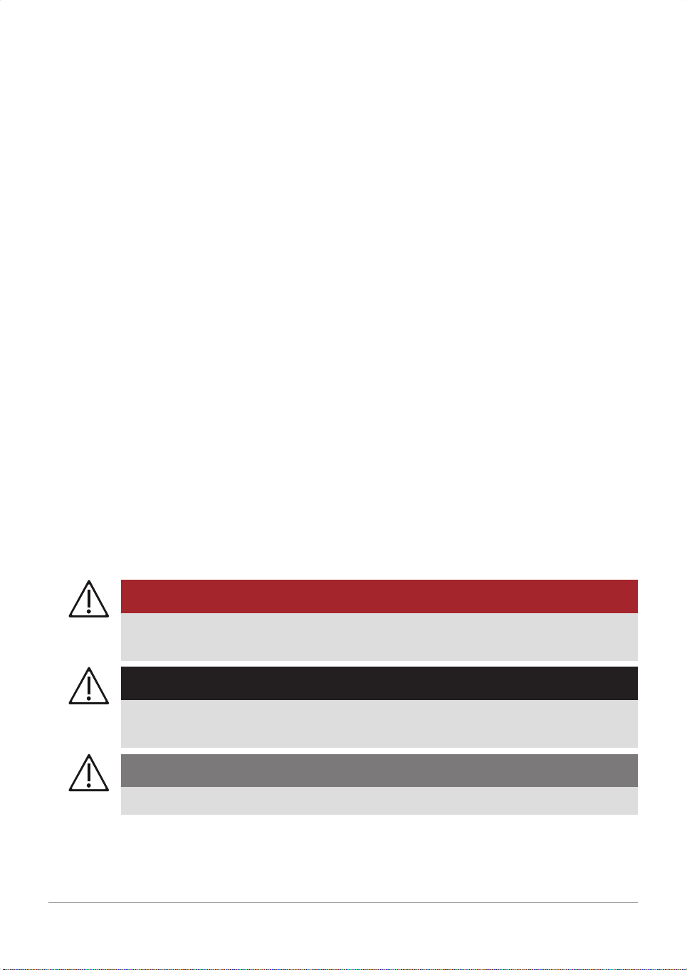
1.1.2 Definitions
DANGER!
Identifies an immediate, serious risk to people which will result in death or
serious injury.
WARNING!
Identifies a general, serious risk to people which can result in death or serious
injury.
CAUTION!
Identifies a possible risk which can result in injury.

|HCU40|1General|9|
InstructionsforUse|1.0|EN|01
CopyrightMaquetCardiopulmonaryGmbH
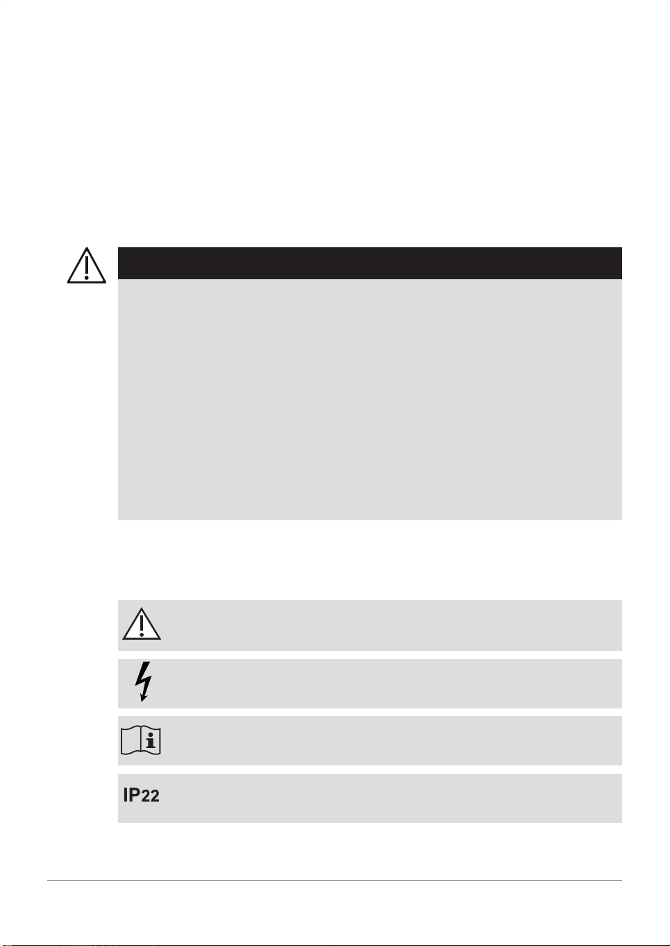
NOTICE!
Identifies a possible risk to property which can result in equipment damage and/
or data loss.
Structure of the other information
Information concerning events without personal injury or equipment damage is
indicated as follows:
NOTE
Additional support and other helpful information.
1.2 Environmental Protection
1.2.1 Packaging
All packaging materials are made of environmentally safe materials. On request,
Maquet will be happy to dispose of the packaging materials.
1.2.2 Batteries
Batteries can be disposed of via the local recycling center.
1.2.3 Disposal
To ensure optimal utilization of the raw materials, the device as well as the
components and accessories must not be disposed of with normal domestic
waste. Keep separate from domestic waste and dispose of in an environmentally
safe way in compliance with local regulations.
nBefore disposal, decontaminate all parts in accordance with the procedures
applicable in clinical practice.
nIn order to prevent risks during disposal, contact the authorized service
personnel.
1.3 Abbreviations
Abbreviation Meaning
CAN ControllerAreaNetwork
CPLG Cardioplegia
CU Controlunit

|10|1General|HCU40|
InstructionsforUse|1.0|EN|01
CopyrightMaquetCardiopulmonaryGmbH
HCU Heatercoolerunit
Text Temperaturemeasuredattheexternalsensor
Tout Temperaturemeasuredatthewateroutlet
Tset Setpointtemperature
Ttank Temperaturemeasuredinthetank
USB Universalserialbus
ΔT Setpointgradient

|HCU40|2Safety|11|
InstructionsforUse|1.0|EN|01
CopyrightMaquetCardiopulmonaryGmbH
2 Safety
2.1 Intended Use
NOTE
Heat exchanger
Please observe the Instructions for Use for the employed heat exchangers with
regard to the indications, intended use, intended user, intended patient, intended
environment, and contraindications.
2.1.1 Indications
The intended purpose of the heater-cooler unit HCU40 is cooling and warming a
patient and maintaining the patient temperature at the required level during
cardiovascular interventions. Temperature changes are effected by means of a
combined oxygenator with heat exchanger in the extracorporeal perfusion circuit.
The system comprises two separate water circuits with temperature regulation.
The first circuit is for connecting the oxygenator heat exchanger and/or the
warming/cooling blanket; the second circuit is intended for connecting the
cardioplegia heat exchanger. Heat exchange between the patient and the
cardioplegic fluid occurs by the temperature-regulated water flowing through the
heat exchanger and/or the warming/cooling blanket. The water temperature of the
patient water circuit and the cardioplegia water circuit can be regulated
independently of each other. The water temperature can be set between 1°C and
40.5°C.
External temperature sensors can be optionally combined with the HCU40, and
can be used to operate the HCU40 in gradient mode. The purpose of this mode
is to provide physiologically optimized warming and cooling of the patient.
2.1.2 Intended Use
The heater-cooler unit HCU40 is intended for cooling or warming a patient
connected to the extracorporeal perfusion circuit and keeping the required patient
temperature constant. The temperature transfer occurs via a heat exchanger in
the patient perfusion circuit and/or cardioplegia water circuit and/or via a warming/
cooling blanket.
2.1.3 Intended User
The HCU40 may only be operated by trained specialist medical staff.

|12|2Safety|HCU40|
InstructionsforUse|1.0|EN|01
CopyrightMaquetCardiopulmonaryGmbH
2.1.4 Intended Patient
The device can be used for all patients irrespective of age, body weight and
gender.
2.1.5 Intended Environment
The HCU40 is used in a clinical environment.
2.1.6 Contraindications
When the heater-cooler unit HCU40 is used by specially trained personnel under
the supervision of a physician and in compliance with the intended use, no
contradictions are to be expected.
2.2 General Safety Instructions
2.2.1 Precautionary Measures
WARNING!
nThe system must be monitored by a trained member of specialist medical
staff. Clinical procedures and methods are the responsibility of the physician.
nYou should always keep a replacement unit on standby in order to ensure
continuous operation in the event of a complete system failure.
nPrior to using the system, please read these Instructions for Use and the
Instructions for Use of all the disposables and supplies used.
nThe HCU40 and all the system components used must comply with the
requirements of IEC 60601-1: 2005, section 16. In case of doubt, contact the
manufacturer of the system components used.
WARNING!
nIt is not permitted to change or modify the device or its accessories.
nSwitch the unit off and disconnect it from the external power supply before
maintenance, cleaning, or storage.
nOnly use the stated substances for descaling/disinfection (⇨ "Cleaning,
descaling and disinfection", page 91).
nIf a defective warming/cooling blanket is used with an electrosurgical unit
which is either not grounded or incorrectly grounded, this may result in burns
to the patient (⇨ "Connecting a Heat Exchanger", page 52).

|HCU40|2Safety|13|
InstructionsforUse|1.0|EN|01
CopyrightMaquetCardiopulmonaryGmbH
2.2.2 Position of Use and Operation and Positioning of the HCU 40
The HCU40 must be positioned so that the user can see all of the displays at all
times, can operate all of the controls and components and access interfaces, and
so that the HCU40 is not interfered with by other devices or vice versa.
WARNING!
nEnsure that the operating position requirements of the attached disposable
are complied with (⇨ Instructions for Use of the disposable).
nEnsure that you can see the touchscreen of the HCU40 as well as any
optical warning signals at all times. In noisy environments, there is a risk that
acoustic warning signals emitted by the HCU40 may not be heard.
nDo not use the system in the presence of escaping flammable or combustible
gases.
nOnly operate the HCU40 within the specified ambient conditions (⇨ "Ambient
Conditions", page 137).
Ambient temperatures outside of the specified conditions can disrupt the
sensors' measurements.
nWhenever the device is moved, the mains voltage must be checked by
personnel authorized for this purpose. In the event of any extreme difference
in voltage from the rated voltage (lower/higher: see rating plate), adjustment
may be carried out by authorized service personnel.
WARNING!
nOnly attach the intended components to the HCU40. Otherwise, the limits of
the safe workload may be exceeded and the mechanical stability of the
HCU40 may be affected.
nThe standard slide rail on the rear of the HCU40 has a maximum load
capacity of 15 kg. Ensure that you do not exceed this load limit.
nAll connected parts, devices, and modules must be firmly and correctly
connected. Check mechanical stability.
nEnsure that the speaker openings are not covered. There is a risk that
acoustic warning signals may not be heard.
nMake sure that the ventilation openings are not obstructed and the HCU40 is
not covered. There is a risk that the HCU40 will overheat and fail. Ensure a
minimum distance of 50 cm from other devices, objects, or the wall.

|14|2Safety|HCU40|
InstructionsforUse|1.0|EN|01
CopyrightMaquetCardiopulmonaryGmbH
2.2.3 Handling the HCU40
WARNING!
nDuring an application, only use devices and equipment which are functioning
perfectly.
nDo not connect equipment which does not form part of this system.
nDo not touch the touchscreen with sharp or pointed objects.
nOnly use the approved liquids as per the Instructions for Use in and on the
HCU40.
nDo not touch the plugs of the HCU40 as electrostatic charges and moisture
may cause damage.
nDo not disconnect any plugs or cables from the HCU40 or the control unit
(CU) during operation.
nIf the CAN connection cable between HCU40 and control unit (CU) is not
connected during operation, immediately reconnect the cable (⇨ "Connecting
a Control Unit", page 39).
nIf a cable proves to be defective, replace it with a cable which functions
correctly.
nIf a plug is faulty, do not operate the device.
nIf the touch screen of the control unit (CU) does not display anything or fails
to react, the CU must be reset. Disconnect and reconnect CAN connection
cable between HCU40 and CU. Check the set values.
nIf, during a power failure, no visual or acoustic alarms are emitted by the
HCU40, it is possible that the independent power supply (UPS) is defective.
Have the device checked/repaired by authorized service personnel. Use a
replacement device in an emergency.
2.2.4 Water Circuits and Heat Exchangers
WARNING!
nSwitch the device off before intra-hospital transportation. Remove all
connected cables.
nObserve the shipping information (⇨ "Send Device to Authorized Service
Point", page 131).

|HCU40|2Safety|15|
InstructionsforUse|1.0|EN|01
CopyrightMaquetCardiopulmonaryGmbH
WARNING!
nObserve the Instructions for Use for the heat exchangers employed.
nObserve the permissible values for heat exchangers (⇨ "Permissible Heat
Exchangers", page 136).
nThe pressure limit must be set by the authorized service personnel in
accordance with the permissible pressure of the heat exchangers. Have the
pressure limit adjusted by the authorized service personnel if you use other
heat exchangers with a lower permissible maximum pressure than the set
pressure limit.
nUse the HCU40 and heat exchanger at the same height in order to avoid an
increase in pressure between the HCU40 and the heat exchanger.
nThe water tank must only be filled with sterile filtered water and other
substances which have been specified by Maquet.
nCheck all water tubes and tube connections for leaks prior to the application.
nKeep the tubes away from sources of heat.
nThe length of the tube from the HCU40 to the heat exchanger must be at
least 1 m.
WARNING!
nTurn the cardioplegia water circuit pump off if no cardioplegic solution is
required.
nIf the tubes are not connected to a heat exchanger, connect the ends of the
tubes to the cleaning connector.

|16|2Safety|HCU40|
InstructionsforUse|1.0|EN|01
CopyrightMaquetCardiopulmonaryGmbH
2.2.5 Monitoring and Sensors
WARNING!
nThe water quality can influence the ice sensors which, in turn, can influence
ice formation. Perform a visual inspection of the actual ice size and adjust the
setpoint ice block size should the actual ice size differ from the setpoint size.
nThe following parameters must be monitored continually by an independent
monitoring and alarm system during application.
- Temperature of the patient
- Blood temperature in the perfusion system
- Contact surface temperature of the warming/cooling blanket
nThe external temperature sensors are intended for operating the HCU40 in
gradient mode. They must not be used for measuring the patient's core body
temperature, and their use does not replace independent, external monitoring
of the blood temperature in the perfusion system.
nThe precision of external temperature measurement depends on the
temperature sensor and the disposable.
nExternal temperature sensors must not be autoclaved.
nOnly use the external temperature sensors, with shielding, listed under
"Supplies" for the HCU40.
nWhen operating the unit in gradient mode, the user can set temperature
limits. An alarm is given if the temperature either falls below or exceeds the
limit value.
nThe temperature limits must be set on the basis of physiological criteria.
nIf an alarm occurs, the setpoint and actual temperatures of the water and the
patient's temperature must be checked.
nAfter data have been input by the user, the HCU40 must not be switched off
immediately, as saving the data may take up to 10 seconds.
2.2.6 Extended Applications
WARNING!
While performing longer normothermal applications, avoid abrupt hypothermia,
which could endanger the patient's health, by employing the following measures:
nDo not add any ice;
nDeactivate the ice formation or do not use any ice (⇨ "Changing the Setpoint
Ice Block Size", page 61).
|HCU40|2Safety|17|
InstructionsforUse|1.0|EN|01
CopyrightMaquetCardiopulmonaryGmbH
2.2.7 Electromagnetic Compatibility
The HCU40 complies with the requirements of the IEC 60601-1-2 standard on
electromagnetic compatibility. The system and all accessories and sensors fulfill
the EMC requirements of a typical clinical environment. (⇨ "Electromagnetic
Compatibility (EMC)", page 143)
The user is responsible for ensuring that the clinical environment complies with
the limits prescribed in IEC 60601-1-2. Exceeding these limits may impair the
system's efficiency and safety.
WARNING!
nDo not use the HCU40 in the vicinity of devices that emit high-frequency
signals (e.g., cell phones or high frequency devices). These can cause
excessively strong electromagnetic interference that exceeds the compliance
level of the HCU40.
nObserve normal precautions regarding relative humidity and the electrical
conductivity of clothing in order to minimize the build-up of electrostatic
charges.
nTo ensure safe use, the length of all connection cables of the HCU40 must
not be changed.
nOnly use the specified accessories (⇨ "Accessories", page 133). The use of
other devices, systems, or accessories may increase RF emissions or reduce
the immunity to interference.
2.3 Symbols
Symbols on the rating plates of the HCU and control unit (CU)
Notice!Observethewarningsandsafetyprecautionsgivenintheaccompanyingdocu
mentation.
Warning:Dangerousvoltage
ObservetheinstructionsintheInstructionsforUse!
ProtectiontypeinaccordancewithIEC60529:Protectionagainstingressofsolidforeign
objectslargerthan12.5mmanddrippingwaterwhentiltedupto15°.
|18|2Safety|HCU40|
InstructionsforUse|1.0|EN|01
CopyrightMaquetCardiopulmonaryGmbH
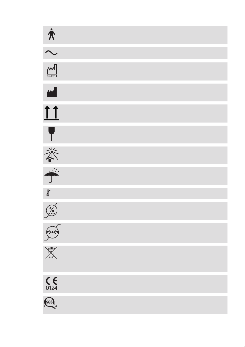
ClassificationinaccordancewithIEC606011:TypeBappliedpart.
Alternatingcurrent
Dateofmanufacture:MonthYearinwhichthedevicewasmade.
ManufacturerasdefinedbyCouncilDirective93/42/EECconcerningmedicaldevices.
Top
Fragile
Donotexposetodirectsunlight
Storeinadryplace
Temperaturerestriction
Airhumidityrestriction
Airpressurerestriction
SeparatecollectionofelectricandelectronicdevicesinaccordancewithDirective
2012/96/EC:Donotdisposeofthedevicewithnormaldomesticwaste.Keepseparate
fromdomesticwasteanddisposeofinanenvironmentallysafewayincompliancewith
localregulations.
ThedevicemeetstherequirementsofCouncilDirective93/42/EECconcerningmedical
products.
710165
ThedeviceconfirmstoCanadianandAmericansafetystandardsCSAC22.2No.601.1
andUL606011.

|HCU40|2Safety|19|
InstructionsforUse|1.0|EN|01
CopyrightMaquetCardiopulmonaryGmbH
FollowtheInstructionsforUse!
Symbols on HCU
"Controlunit(CU)"connection
Patientwatercircuit1
Patientwatercircuit2
Cardioplegiawatercircuit
Wateroutlet
Waterinlet(backflow)
Portforexternalpowersupply
Equipotentialbonding
Symbols on the housing of the control unit (CU)
"Text"connectionforcardioplegiawatercircuit
"HLM"connection(notused)
"HCU"connection
USBport
"Text"connectionforpatientwatercircuit
|20|2Safety|HCU40|
InstructionsforUse|1.0|EN|01
CopyrightMaquetCardiopulmonaryGmbH
Symbols on the supply to the warming/cooling blanket
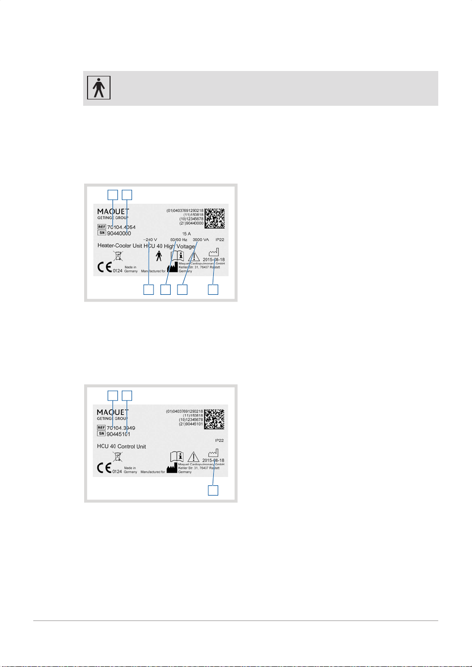
ClassificationinaccordancewithIEC606011:TypeBFappliedpart
2.4 Rating Plates
HCU40
The rating plate is on the rear of the HCU40.
3
2
456
1
1 Ordernumber
2 Devicespecificserialnumber
3 Devicespecificdateofmanufacture
4 Powerconsumption
5 Frequency
6 ACpowersupply
The values on the rating plate shown are examples and may differ from the rating
plate on the device.
Control unit (CU)
The rating plate is on the rear of the control unit (CU).
3
2
1
1 Ordernumber
2 Devicespecificserialnumber
3 Devicespecificdateofmanufacture
Table of contents
Other Maquet Heater manuals


