Maquet HU 35 User manual
HU 35, User's Manual 1
English version
2.00
User’s Manual
Heater Unit HU 35

2HU 35, User's Manual
English version
2.00

HU 35, User's Manual 1
English version
2.00
Table of Contents
1 Brief Instructions....................................................................... 3
2 Safety Instructions .................................................................... 5
3 General Description .................................................................. 7
4 Putting into Operation............................................................. 11
5 Instructions for Use................................................................. 19
6 Cleaning and Disinfection....................................................... 25
7 Maintenance and Safety Checks ............................................ 27
8 Troubleshooting ...................................................................... 31
9 Technical Data and Accessories ............................................ 33
10 Warranty and Liability Limitations ....................................... 39

2HU 35, User's Manual
English version
2.00
HU 35, User's Manual 3
English version
2.00
1. Brief Instructions
1. Connect the unit to the power supply.
2. Attach the oxygenator to the unit via the tubes.
3. Check the unit’s water level.
4. Switch on the unit using the power switch (0/I) and observe the automatic
performance test.
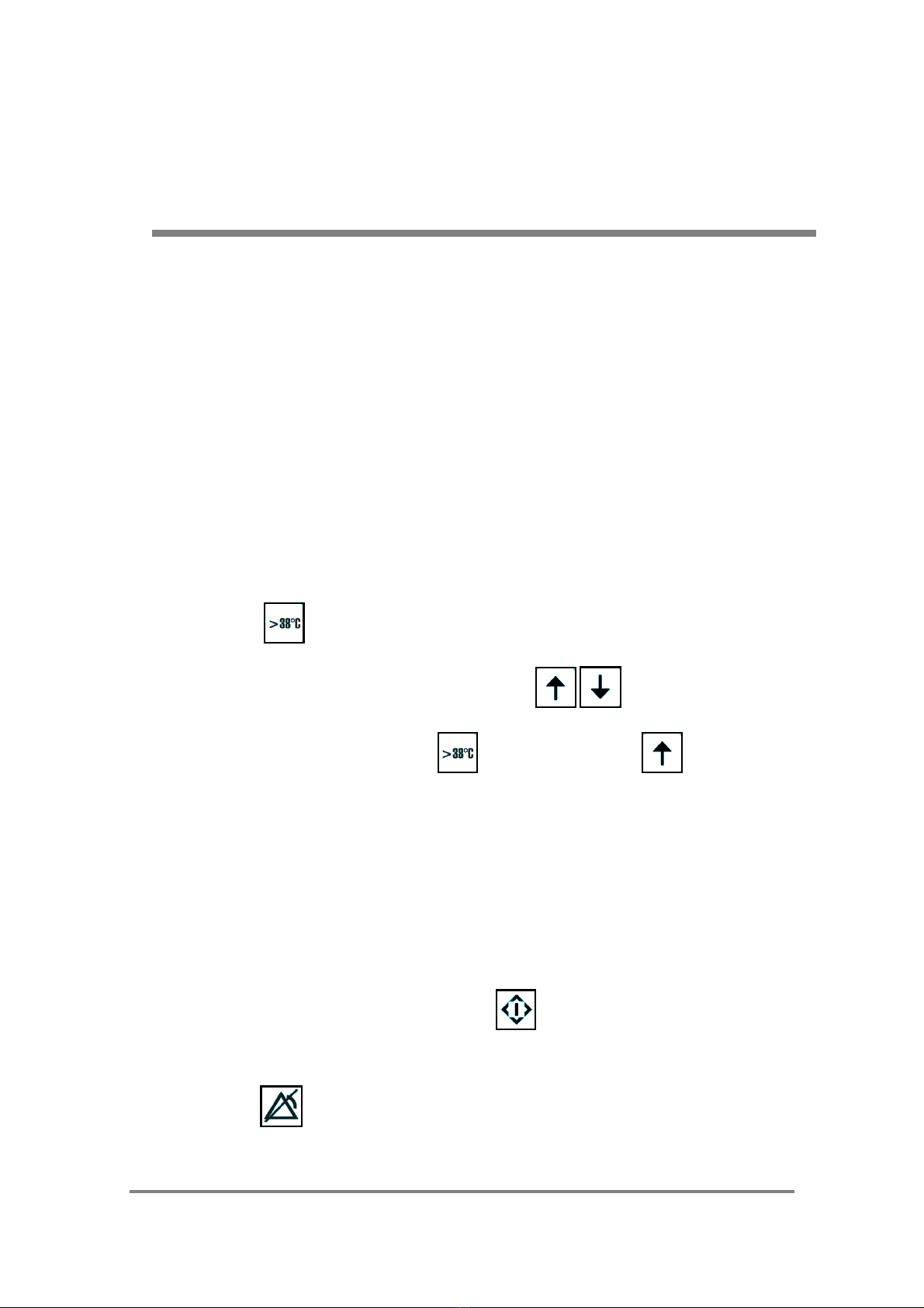
5. If the temperature setpoint is > 38°C when switching on the unit, the alarm
is disabled and the unit is put into operation by pressing the enable key
“>38°C”.
6. Set the temperature using the arrow keys if necessary.
7. Press the enable key “>38°C” and the arrow key simultaneously
for temperatures in excess of 38°C.
8. Monitor the patient’s body temperature.
9. Monitor the unit’s water level and water flow.
10. If the unit is used continuously, carry out the performance test manually by
pressing the “Performance Test” key once daily.
11. Second priority acoustic alarms can be disabled by pressing the “Alarm
Off” key.
12. First priority alarms can be disabled by switching the unit off.
4HU 35, User's Manual
English version
2.00
1. Brief Instructions
Note: re. 12:
If a first priority alarm is sounded, all the unit’s functions are automatically shut
down. The unit must therefore be switched off in order to switch off the alarm
signal. The unit must no longer be used and should be sent to a service
technician for inspection and, if required, restoration of operational safety (see
Chapter 5 “Alarm Signals” and Chapter 8).
The unit must not be used if:
- the display is not functioning;
- the display is faulty (missing segments of numbers could result in
misinterpretation of values);
- the red alarm LED is either continuously lit or does not light up at
all (performance test);
- the signal horn either sounds continuously or does not sound at
all (performance test);
- the unit fails to react when the keys are actuated;
- the unit does not react as described in the User’s Manual when it
is switched on or the performance test is carried out.
These brief instructions do not free the user from his obligation
to observe the User’s Manual and instructions for use for the
respective oxygenator!

HU 35, User's Manual 5
English version
2.00
2. Safety Instructions
• Before putting into operation, the user must ensure that both the unit
(power cord, housing, couplings etc.) and the applied part (oxygenator) are
in proper working order.
• Fill the tank with tap water only.
• Before opening the water tank’s screw cap, the unit must be disconnected
from the power supply. The unit must NOT be operated without the screw
cap.
• The unit must only be operated in a horizontal position away from heat
sources (spotlights, direct sunlight, heating elements, radiant heaters etc.).
• Do not cover the ventilation slots on the bottom and rear of the unit.
• The difference in height between the unit and the oxygenator must not be
more than one meter (1 m).
• Observe the automatic performance test when switching on the unit and, if
the unit is used continuously, perform the test manually at least once daily.
• When in use, the unit’s water flow and water level must be checked
regularly.
• The unit must only be operated with a sufficient water level.
• Do not kink the tubes.
• Observe the ambient temperature range (10 - 30°C) and the storage
temperature range (10 - 40°C).
• Only operate the unit with the MAQUET PLS oxygenator or other
oxygenators and their respective original accessories as part of
extracorporeal circuits.
• The unit must not be used in the presence of flammable gases.
• Carry out maintenance work and safety checks in accordance with the
User’s Manual.

6HU 35, User's Manual
English version
2.00
2. Safety Instructions
............................................................................................................................
............................................................................................................................
............................................................................................................................
............................................................................................................................
............................................................................................................................
............................................................................................................................
............................................................................................................................
............................................................................................................................
............................................................................................................................
............................................................................................................................
............................................................................................................................
............................................................................................................................
............................................................................................................................
............................................................................................................................
............................................................................................................................
............................................................................................................................
............................................................................................................................
............................................................................................................................
............................................................................................................................
............................................................................................................................
............................................................................................................................
............................................................................................................................
............................................................................................................................
............................................................................................................................
............................................................................................................................
............................................................................................................................
............................................................................................................................
............................................................................................................................
............................................................................................................................

HU 35, User's Manual 7
English version
2.00
3. General Description
Figures.......................................................................................... 8
Product Description................................................................... 10
Intended Purpose / Indications ................................................. 10
Side Effects / Contraindications ............................................... 10
8HU 35, User's Manual
English version
2.00
3. General Description
Figures
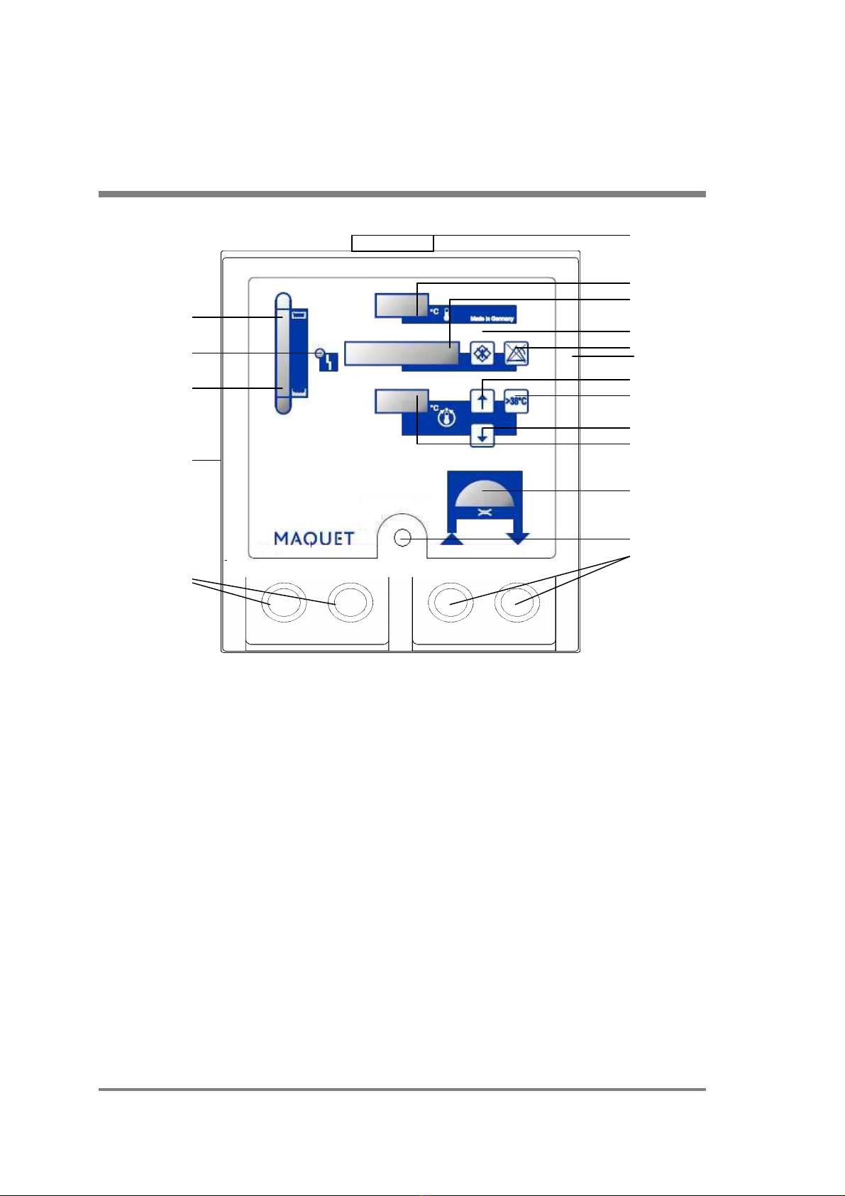
Figure 1: Front
1 Water filler neck with screw cap
2 Actual temperature display
3 Status and error messages display
4 “Performance Test” key
5 “Alarm Off” key
6 “Increase Temperature Setpoint” arrow key
7 “Temperature Setpoint greater than 38°C” enable key
8 “Decrease Temperature Setpoint” arrow key
9 Temperature setpoint display (33 - 39°C)
10 Water flow display for right coupling pair
11 Power switch O/I
12 Right coupling pair for connecting the tubes to the oxygenator
13 Blind plugs in left coupling pair
14 A. Threaded holes (fastening screws on housing) for tubing holder
B. Threaded holes for clamp mounting (accessories)
15 Water level display: min. water level
16 Fault display lamp
17 Water level display: max. water level
1
2
3
4
5
14A
6
7
8
9
10
11
12
17
16
15
14B
13
HU 35, User's Manual 9
English version
2.00
3. General Description
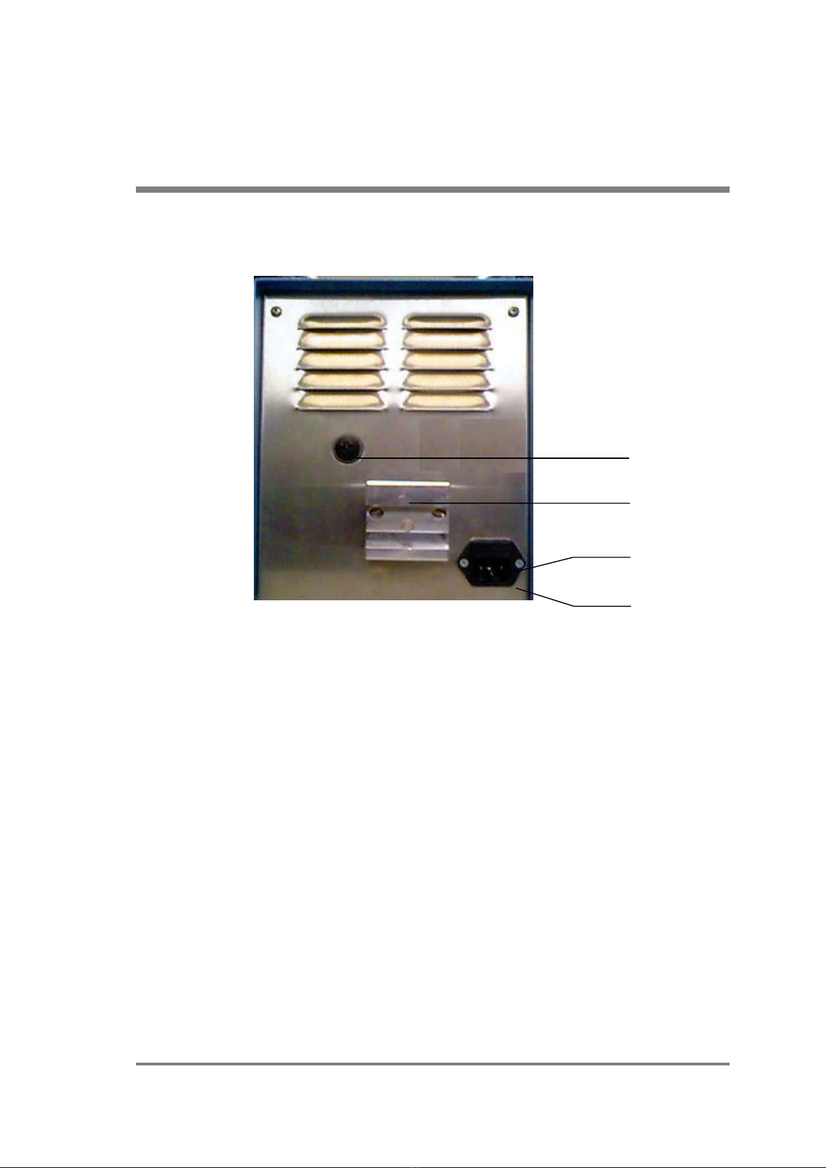
Figure 2: Rear
1 Water outflow point with screw cap
2 Clamp mounting (accessories)
3 Line fuses (2 x T 3.15 A)
4 Connector plug for power cord
1
2
3
4

10 HU 35, User's Manual
English version
2.00
3. General Description
Product Description
The Heater Unit HU 35 works on the principle of heat dissipation via a thick
membrane to the blood stream with an oxygenator.
A heating element heats up the water in the unit’s water tank, this water is
electronically controlled and pumped continuously.
The Heater Unit HU 35 is characterized by its compact design, simple and safe
handling and reliability.
The Heater Unit HU 35’s main features are its efficient and precise heat
transfer and its outstanding operational safety.
The various displays on the front of the unit provide information on the proper
functioning of the device at all times. Operation is both simple and intuitive. The
temperature on the unit can be set between 33°C and 39°C, which enables
body temperature to be maintained.
Intended Purpose / Indications
The Heater Unit HU 35 acts as a heat supply in order to maintain the patient’s
body temperature via a MAQUET PLS oxygenator or other oxygenators as part
of extracorporeal circuits.
Side Effects / Contraindications
There are no side effects and no known contraindications when the Heater Unit
HU 35 is used for the intended purpose.

HU 35, User's Manual 11
English version
2.00
4. Putting into Operation
Setting up the Unit ..................................................................... 12
Language.................................................................................... 13
Water Level................................................................................. 14
Oxygenator................................................................................. 15
Putting into Operation ............................................................... 16
12 HU 35, User's Manual
English version
2.00
Figure 3
Figure 4
Figure 5
4. Putting into Operation
Setting up the Unit
a) Table top unit
The Heater Unit HU 35 hyperthermia system
unit is designed for use on table tops, i.e., it can
be placed on all types of flat, horizontal, hard
and load-bearing surfaces. For safety reasons,
the unit must not be operated on the floor.
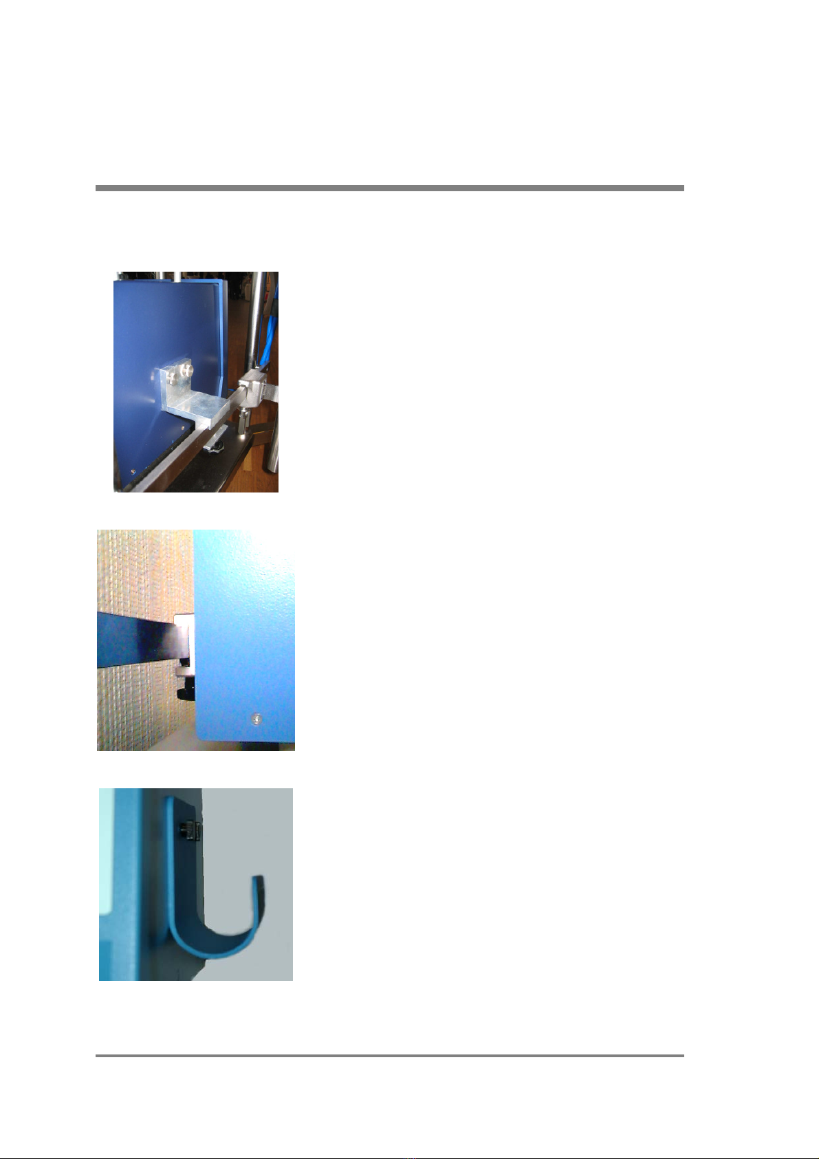
b) Mobile floor-mounted unit
Together with the SPRINTER Cart as an
optional accessory and the respective clamp
mounting, the unit can be used as a mobile
floor-mounted appliance.
The clamp mounting for the SPRINTER Cart is
secured on the left side of the unit (see Figure 3)
using two screws. The unit is secured to the
slide rail of the SPRINTER Cart using the star
screw on the clamp mounting.
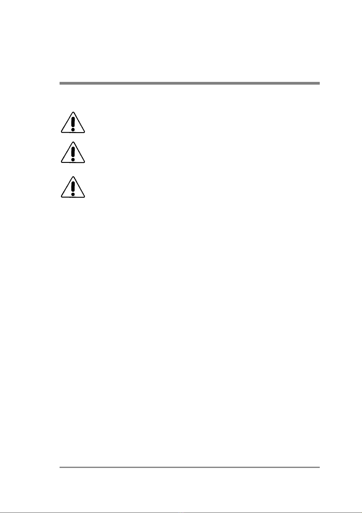
c) Wall mounting on slide rails
The unit can be attached to the standard slide
rails (25 x 10 mm) found in hospitals. To this end,
the clamp mounting, which is available as an
accessory, is ideally secured to the rear of the
unit using two screws. The unit is secured to the
rail using the star screw on the clamp mounting
(see Figure 4).
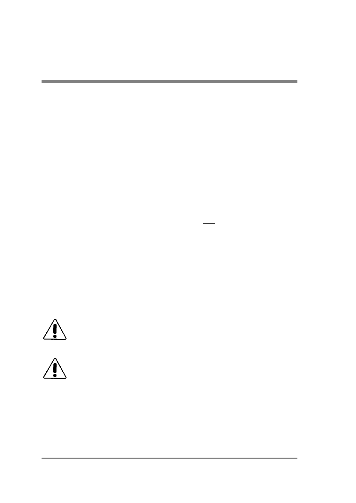
d) Tubing holder
If necessary, the tubing holder, which is
available as an accessory, can be attached to
the right-hand side of the unit using the knurled
screws located there (see Figure 5).
HU 35, User's Manual 13
English version
2.00
4. Putting into Operation
The following must be observed when setting up the unit:
When setting up the unit it must be ensured that the ventilation slots
on the bottom and rear of the unit are not covered.
When in operation, the unit must be in a horizontal position (max.
incline of 2°) as otherwise the water level display on the front of the
unit displays an incorrect value.
Furthermore, it is also recommended that the unit is positioned level or
slightly higher than the oxygenator (max. height difference 1 m) due to
the water pressure conditions in the circulation system. Moreover,
when opening the water filler neck when the unit is switched off, water
from the tubes and oxygenator can flow back into the unit causing the
water tank to overflow.
Language
The language in the display (Fig. 1 point 3) on the front of the unit, which
provides information on the status and error messages, can be changed by the
user. The following languages are available: German, English, French, Spanish,
Italian.
The language is set, with the unit switched on, as follows:
1.) Keep the “Alarm Off” key (Fig. 1 point 5) depressed (4 seconds) until the
language appears in the display.
2.) Pressing the “Increase Setpoint” key (Fig. 1 point 6) serves to display and
activate the languages in the following order: German, English, French,
Spanish, Italian, German etc..
3.) The selection option automatically ends 10 seconds after the last entry.
14 HU 35, User's Manual
English version
2.00
4. Putting into Operation
Water Level
a) Checking
Before switching the unit on and connecting the tube to the oxygenator, the
water level must be checked. The water level display is located on the front of
the unit, the display has a minimum (Fig. 1 point 15) and maximum (Fig. 1 point
17) permissible value. The water level must be between these two values,
whereby the maximum value should be aimed for. The difference between the
two values is 0.7 liters.
Water must be refilled under the following conditions:
the water level is below the minimum value;
the display shows “WATER LEVEL!?”;
empty tubes and an oxygenator are connected and the water level is below
the maximum value.
b) Filling / Refilling
The water tank is filled with tap water. The unit is filled after it has been
switched off and disconnected from the power supply. To pour in water, the
screw cap (Fig. 1 point 1) of the water filler neck is removed (e.g., using a coin).
After being filled, the water level should be slightly below the max. value on the
display. Once the water has been poured in, the screw cap should be screwed
on lightly.
Operators should not use any cleaning or decontamination methods
other than those recommended by the manufacturer without checking
with the manufacturer beforehand whether the suggested methods
could cause damage to the unit.
If, when filling, water flows over the unit, this must be dried thoroughly.
The unit must not be used again until it is completely dry.
c) Changing the water
The water must be changed every two weeks (see also Chapter 7 “Maintenance
and Safety Checks”)

HU 35, User's Manual 15
English version
2.00
4. Putting into Operation
Oxygenator
An oxygenator can be attached either before or after the unit is switched on.
The tube couplings are simply connected to the right-hand coupling pair on the
unit (Fig. 1 point 12). The couplings are correctly attached to each other when
the lock on the tube coupling clicks into place in the unit’s coupling nipple and
the connection can no longer accidentally become undone.
On the oxygenator side, the tube is connected to the oxygenator via an adapter
on a Hansen coupling. The used Hansen couplings can be connected with all
current oxygenators. The connection is correct if the water flow display above
the coupling pair on the unit rotates when the unit is switched on.
The coupling is released by pressing on the small metal plate on the tube
coupling. The couplings can be released when the unit is switched on. It must
be ensured, however, that the adapter on the oxygenator side is decoupled as
otherwise water will leak out. The system has been designed so that, after
release, the coupling drips briefly; this is not a sign of a leakage or fault.
Tip
The black sealing rings on the couplings can become dry, brittle and stiff as a
result of ageing. This can be remedied by applying a thin film of silicone
grease, Vaseline or similar to the sealing ring.
The unit must only be operated with the MAQUET PLS oxygenator or other
oxygenators as part of extracorporeal circuits.
The used oxygenators need to resist a pressure of a maximum of 0.34 Bar
and to allow a maximum temperature of 40°C (independent safety shutdown).
For further information, please refer to the oxygenator’s instructions for use.
An oxygenator must not be connected when performing disinfection (also see
Chapter 6 “Cleaning and Disinfection”).

16 HU 35, User's Manual
English version
2.00
4. Putting into Operation
Putting into Operation
The unit can be connected to the power supply using the power plug, taking into
account points “Setting up the Unit” – “Oxygenator”.
Switching on (O/I)
The power switch is designed as a push switch with the symbols O/I and is
located on the front of the unit (Fig. 1 point 11). The unit is switched on when
the power switch button is depressed into the recess and off when the button is
flush with the front of the unit.
Performance Test
A short acoustic alarm sounds when the unit is switched off and on. This signals
that the power failure alarm is ready. Shortly after switching the unit on, a
performance test checks the independent safety device and the result is shown
in the display. Furthermore, all the segments (88.8) of the temperature displays,
the fault display lamp and the acoustic alarm are activated at the same time.
This performance test takes just a few seconds, during this time the user must
observe the activation of the above-named displays.
Warm-up Phase
Once the performance test has been completed, the temperature control
mode starts automatically if the temperature is set between 33 and 38°C.
If the set value is greater than 38°C, an acoustic alarm sounds and the
following messages are displayed “SET VALUE >38°C”, “ENABLE KEY -
>”. The temperature control mode is started by pressing the enable key
“>38°C” (Fig. 1 point 7).
HU 35, User's Manual 17
English version
2.00
4. Putting into Operation
Once the setpoint temperature has been reached, heat dissipation in watts (W)
is shown in the display (also see Chapter 5 “Heat Dissipation”).
The unit must be taken out of use in the following examples and
inspected by the authorized customer service organization:
the short acoustic power failure alarm cannot be heard when
switching the unit on and off;
the automatic performance test identifies a defect in the independent
safety device and automatically switches the unit off;
the user notes a defect in the displays.
The unit is not designed for continuous use without an oxygenator. If
the unit is operated for an extended period (> 1h) without an
oxygenator, various alarm messages may be given due to the lack of
heat dissipation, in this case such messages do not point to a defect,
but rather signal the proper functioning of the safety devices. The unit
can be used again after a cooling down period.
When used with an oxygenator, the patient’s body temperature should
be monitored.

18 HU 35, User's Manual
English version
2.00
4. Putting into Operation
............................................................................................................................
............................................................................................................................
............................................................................................................................
............................................................................................................................
............................................................................................................................
............................................................................................................................
............................................................................................................................
............................................................................................................................
............................................................................................................................
............................................................................................................................
............................................................................................................................
............................................................................................................................
............................................................................................................................
............................................................................................................................
............................................................................................................................
............................................................................................................................
............................................................................................................................
............................................................................................................................
............................................................................................................................
............................................................................................................................
............................................................................................................................
............................................................................................................................
............................................................................................................................
............................................................................................................................
............................................................................................................................
............................................................................................................................
............................................................................................................................
............................................................................................................................
............................................................................................................................
Other manuals for HU 35
1
Table of contents
Other Maquet Heater manuals


