Marantz 50 User manual

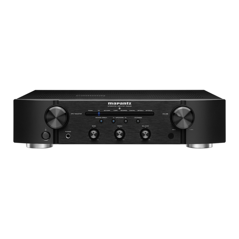
Integrated Amplifier
Owner’s Manual
1

Accessories 4
Inserting the batteries 5
Operating range of the remote control unit 5
Part names and functions 6
Front panel 6
Rear panel 8
Remote control unit 10
Connections
Connecting speakers 14
Speaker A/B connection 16
Bi-wiring connection 17
Subwoofer connection 18
Connecting a playback device 19
Connecting a recording device 20
Connecting a pre-amplifier or power amplifier 21
Connecting devices with remote control connectors 22
Performing operations by RC on this unit without visual contact 22
Remotely connecting Marantz audio devices 22
Connecting the power cord 24
Playback
Turning the power on 26
Switching the power to standby 26
Selecting the speakers for audio output 27
Selecting the input source 27
Adjusting the volume 27
Turning off the sound temporarily (Muting) 28
Adjusting the tone and balance 28
Playback in source direct mode 28
Playing CDs 28
Using this unit as a power amplifier 29
Recording 29
Contents Connections Playback Settings Tips Appendix
2
Front panel Rear panel
Remote control
unit
Index

Settings
Setting the display’s brightness 31
Setting the Auto Standby mode 32
Setting remote control codes 33
Setting remote control codes for the remote control 34
Setting remote control codes for the main unit 34
Tips
Tips 36
Troubleshooting 37
Power does not turn on / Power is turned off 38
Operations cannot be performed through the remote control unit 40
Display on this unit shows nothing 41
No sound comes out 41
Desired sound does not come out 42
Sound is interrupted or noise occurs 43
Appendix
Explanation of terms 44
Specifications 45
Index 47
Contents Connections Playback Settings Tips Appendix
3
Front panel Rear panel
Remote control
unit
Index

Thank you for purchasing this Marantz product.
To ensure proper operation, please read this owner’s manual carefully before using the product.
After reading this manual, be sure to keep it for future reference.
Accessories
Check that the following parts are included with the product.
Quick Start Guide Safety Instructions Cautions on Using Batteries Power cord
2× R03/AAA batteries
Remote control unit
(RC003PMND)
Contents Connections Playback Settings Tips Appendix
4
Front panel Rear panel
Remote control
unit
Index

Inserting the batteries
1Remove the rear lid in the direction of the arrow and
remove it.
2Insert two batteries correctly into the battery
compartment as indicated.
Batteries
3Put the rear lid back on.
NOTE
0To prevent damage or leakage of battery fluid:
0Do not use a new battery together with an old one.
0Do not use two different types of batteries.
0Remove the batteries from the remote control unit if it will not be in use for long
periods.
0If the battery fluid should leak, carefully wipe the fluid off the inside of the battery
compartment and insert new batteries.
Operating range of the remote control
unit
Point the remote control unit at the remote sensor when operating it.
Approx. 7 m
30° 30°
Contents Connections Playback Settings Tips Appendix
5
Front panel Rear panel
Remote control
unit
Index

we r
qt
uioQ
0
Q
1
y
APower X button
This turns the power on/off (standby). (v p. 26)
BDisplay
This displays various pieces of information.
CRemote control sensor
This receives signals from the remote control unit. (v p. 5)
DProtection circuit indicator
This blinks when the protection circuit has operated. (v p. 38)
EHeadphones jack
Used to connect headphones.
Turn the SPEAKERS selector knob on the main unit to turn off speaker
output when using headphones. (v p. 27)
NOTE
0To prevent hearing loss, do not raise the volume level excessively when using
headphones.
FINPUT selector knob
This selects the input source. (v p. 27)
GSPEAKERS selector knob
This selects the speaker for audio output. (v p. 27)
HBASS control knob
This setting adjusts the volume level for the bass. (v p. 28)
ITREBLE control knob
This setting adjusts the volume level for the treble. (v p. 28)
JBALANCE control knob
This adjusts the balance of the volume output from the left and right
speakers. (v p. 28)
KVOLUME knob
This adjust the volume level. (v p. 27)
08, 9 and 0 can be adjusted when source direct mode is off. (v p. 28)
Contents Connections Playback Settings Tips Appendix
7
Front panel Rear panel
Remote control
unit
Index

qw e r
uyt oi
AAnalog audio input connectors (AUDIO IN)
Used to connect devices equipped with analog audio output
connectors.
0“Connecting a playback device” (v p. 19)
0“Connecting a recording device” (v p. 20)
BSIGNAL GND terminal
Used to connect the ground wire of a turntable. (v p. 19)
CSpeaker terminals (SPEAKERS)
Used to connect speakers. (v p. 14)
DAC inlet (AC IN)
Used to connect the power cord. (v p. 24)
EAUDIO OUT connectors (RECORDER)
Used to connect the input connector of a recorder. (v p. 20)
FPRE OUT connectors
Use this to add such equipment as a power amplifier or subwoofer.
0“Subwoofer connection” (v p. 18)
0“Connecting a pre-amplifier or power amplifier” (v p. 21)
0When connecting a subwoofer, also consult the subwoofer instruction manual.
GPower amplifier connectors (POWER AMP IN)
Used to connect a pre-amplifier when this unit is used as a power
amplifier. (v p. 21)
HRemote control input/output connectors (REMOTE CONTROL)
Used to connect to a Marantz audio device that is compatible with the
remote control function. (v p. 22)
IEXTERNAL/INTERNAL switch
Turn this switch to “EXTERNAL” to operate the unit by pointing the
remote control at the audio device connected to this unit using the
remote control connection. (v p. 22)
Contents Connections Playback Settings Tips Appendix
9
Front panel Rear panel
Remote control
unit
Index

Remote control unit
w
e
y
r
t
q
u
The remote control provided with this unit can control a Marantz Network
CD player.
0“Network CD player operations” (v p. 11)
oOperating this unit
ARemote control signal transmitter
This transmits signals from the remote control unit. (v p. 5)
BINPUT buttons (ml)
This selects the input source. (v p. 27)
CMute button (:)
This mutes the output audio. (v p. 28)
DPower (AMP X) button
0This turns the power on/off (standby). (v p. 26)
0This turns auto standby mode on/off. (v p. 32)
ESOURCE DIRECT button
This turns source direct mode on/off. (v p. 28)
FVOLUME buttons (no)
These adjust the volume level. (v p. 27)
GDIMMER button
Adjust the display brightness of this unit. (v p. 31)
Contents Connections Playback Settings Tips Appendix
10
Front panel Rear panel
Remote control
unit
Index

q
e
w
r
i
o
Q0
Q1
t
y
u
oNetwork CD player operations
A Marantz Network CD player can be operated.
APower (CD X) button
BDisc tray open/close button (q)
CInput source select buttons
DSystem buttons
EQUEUE button
PROGRAM button
FENTER button
GCursor buttons
HBACK button
INumber/letter buttons (0 – 9, a/A)
JRANDOM button (s)
KREPEAT button (r)
Contents Connections Playback Settings Tips Appendix
11
Front panel Rear panel
Remote control
unit
Index

Q7
Q8
Q4
Q6
Q2
Q9
Q5
Q3
LSLEEP button
MVOLUME buttons (no)
NOPTION button
OMute button (:)
PSETUP button
QCLEAR button
RInformation button (INFO)
SDIMMER button
0The remote control may not operate some products.
0c and e only work when the remote control code is set to Network CD player
operation mode. See the instruction manual of your Marantz Network CD player
for details.
Contents Connections Playback Settings Tips Appendix
12
Front panel Rear panel
Remote control
unit
Index

oContents
Connecting speakers 14
Connecting a playback device 19
Connecting a recording device 20
Connecting a pre-amplifier or power amplifier 21
Connecting devices with remote control connectors 22
Connecting the power cord 24
NOTE
0Do not plug in the power cord until all connections have been completed.
0Do not bundle power cords together with connection cables. Doing so can result in
humming or noise.
oCables used for connections
Provide necessary cables according to the devices you want to
connect.
Speaker cable
Subwoofer cable
Audio cable
R
L
R
L
Remote connector cable
Contents Connections Playback Settings Tips Appendix
13
Front panel Rear panel
Remote control
unit
Index

Connecting speakers
NOTE
0Disconnect this unit’s power plug from the power outlet before connecting the
speakers.
0Connect so that the speaker cable core wires do not protrude from the speaker
terminal. The protection circuit may be activated if the core wires touch the rear
panel or if the + and - sides touch each other. (“Protection circuit” (v p. 44))
0Never touch the speaker terminals while the power cord is connected. Doing so
could result in electric shock.
0Use speakers with impedances within the ranges shown below to suit how they
are used.
Speaker terminals
used on this unit
No. of connected
speakers
Speaker
Impedance
SPEAKERS A
(Standard
connection)
2 (one set) 4 – 16 Ω/ohms
SPEAKERS B 2 (one set) 4 – 16 Ω/ohms
SPEAKERS A and
SPEAKERS B 4 (two sets) 8 – 16 Ω/ohms
SPEAKERS A and
SPEAKERS B
(Bi-wiring
connection)
2 (one set) 4 – 16 Ω/ohms
oConnecting the speaker cables
Carefully check the left (L) and right (R) channels and + (red) and - (white)
polarities on the speakers being connected to this unit, and be sure to
connect the channels and polarities correctly.
1
Peel off about 10 mm of sheathing from the tip of the speaker
cable, then either twist the core wire tightly or terminate it.
2
Turn the speaker terminal counterclockwise to loosen it.
3Insert the speaker cable’s core wire to the hilt into the
speaker terminal.
Contents Connections Playback Settings Tips Appendix
14
Front panel Rear panel
Remote control
unit
Index

Speaker A/B connection
This unit is equipped with two sets of speaker terminals (SPEAKER A and SPEAKER B). One set of speakers can be connected to each set of terminals,
and a total of two sets of speakers can be connected.
The same signal is output from the SPEAKERS A and SPEAKERS B terminals.
When only one set of speakers is to be connected, use either the SPEAKERS A or SPEAKERS B terminals.
wqwq wqwq
SPEAKERS A SPEAKERS B
(R) (L) (R) (L)
Contents Connections Playback Settings Tips Appendix
16
Front panel Rear panel
Remote control
unit
Index

Bi-wiring connection
This connection limits the effects of signal interference between the high range speakers (tweeters) and low range speakers (woofers), allowing you to
enjoy high quality playback.
When bi-wiring with bi-wireable speakers, connect the mid and high range terminals to SPEAKERS B (or SPEAKERS A), the low range terminals to
SPEAKERS A (or SPEAKERS B).
wq
wq
HIGH
LOW
wq
wq
HIGH
LOW
Speaker
(R)
Speaker
(L)
Remove shorting bar Remove shorting bar Remove shorting bar Remove shorting bar
Contents Connections Playback Settings Tips Appendix
17
Front panel Rear panel
Remote control
unit
Index

Subwoofer connection
Use a subwoofer cable to connect the subwoofer.
Subwoofer
0The subwoofer volume is linked to the Speaker A volume.
0This unit does not output to the subwoofer when not set to output audio from the SPEAKERS A terminal. (v p. 27)
Contents Connections Playback Settings Tips Appendix
18
Front panel Rear panel
Remote control
unit
Index

Connecting a playback device
You can connect turntables, tuners, Blu-ray disc players, network audio players and CD players to this unit.
This unit is compatible with turntables equipped with a moving magnet (MM) phono cartridge. When you connect to a turntable with a low output moving
coil (MC) cartridge, use a commercially available MC head amp or a step-up transformer.
If you set this unit’s input source to “PHONO” and you accidentally increase the volume without having a turntable connected, you may hear a hum noise
from the speakers.
NOTE
0The earth terminal (SIGNAL GND) of this unit is not
for safety grounding purposes. If this terminal is
connected when there is a lot of noise, the noise can
be reduced. Note that depending on the turntable,
connecting the ground line may have the reverse
effect of increasing noise. In this case, it is not
necessary to connect the ground line.
0The PHONO input terminals are equipped with a
short pin-plug. Remove this plug to connect a record
player. Store the removed short pin-plug in a safe
place so as not to lose it.
GND
AUDIO
OUT
L
R
AUDIO
OUT
LR
AUDIO
OUT
LR
AUDIO
OUT
LR
AUDIO
OUT
LR
L
L
R
R
L
L
R
R
L
L
R
R
L
L
R
R
Turntable Tu n e r Blu-ray disc
player
Network audio
player CD player
Contents Connections Playback Settings Tips Appendix
19
Front panel Rear panel
Remote control
unit
Index

Connecting a recording device
LR
L
L
R
R
L
L
R
R
LR
AUDIO INAUDIO OUT
Recording device
NOTE
0Never insert the short-circuiting pin plug into the recording output connectors (AUDIO OUT RECORDER). Doing so could result in damage.
Contents Connections Playback Settings Tips Appendix
20
Front panel Rear panel
Remote control
unit
Index
Other manuals for 50
1
Table of contents
Other Marantz Amplifier manuals

Marantz
Marantz PM200 User manual

Marantz
Marantz AV8003 User manual

Marantz
Marantz PS-17 User manual

Marantz
Marantz PM7000/N1B User manual

Marantz
Marantz MA-9S1 User manual

Marantz
Marantz PM66KI User manual

Marantz
Marantz MM7025 User manual

Marantz
Marantz PM-11S3 User manual

Marantz
Marantz THX Ultra MA-6100 User manual

Marantz
Marantz PM6006 User manual

Marantz
Marantz PM7001 User manual

Marantz
Marantz 2440 User manual

Marantz
Marantz 74 PM16/02B User manual

Marantz
Marantz PM6004 User manual

Marantz
Marantz AV7005 User manual

Marantz
Marantz MM8077 User manual

Marantz
Marantz 500 User manual

Marantz
Marantz PM7005 User manual

Marantz
Marantz MA-9S1 User manual
Marantz
Marantz SR7015 User manual