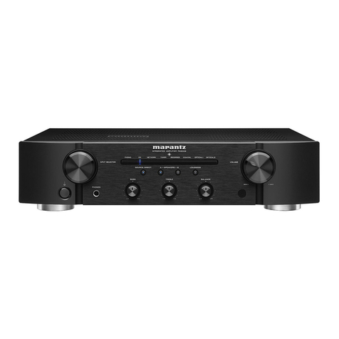
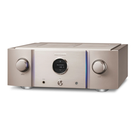
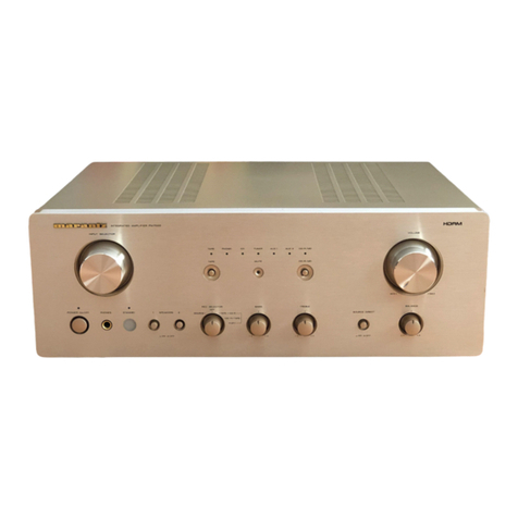
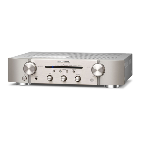
Marantz PM7003 User manual

Please use this service manual with referring to the user guide ( D.F.U. ) without fail.
Service
Manual Integrated Amplifier
PM7003 /F N/K1SG/N1SG
/N1B
TABLE OF CONTENTS
SECTION PAGE
1. TECHNICAL SPECIFICATIONS ........................................................................................... 1
2. ALIGNMENTS....................................................................................................................... 2
3. SERVICE MODE................................................................................................................... 4
4. PROTECTION MODE ........................................................................................................... 5
5. WRITING MAIN MICROPROCESSOR PROCEDURE......................................................... 7
6. WIRING DIAGRAM ............................................................................................................. 25
7. BLOCK DIAGRAM .............................................................................................................. 27
8. SCHEMATIC DIAGRAM...................................................................................................... 29
9. PARTS LOCATION.............................................................................................................. 37
10. EXPLODED VIEW AND PARTS LIST................................................................................. 47
11. MICROPROCESSOR AND IC DATA................................................................................... 51
12. ELECTRICAL PARTS LIST................................................................................................. 56
13. ABOUT REPLACE THE MICROPROCESSOR WITH A NEW ONE............................... 71
PM7003
Part no. 90M24AJ855010
First Issue 2008.07
MZ
PM7003
INTEGRATED AMPLIFIER PM7003
AUX/DVD MUTERECORDER 21TUNERPHONO CD
POWER AMP DIRECT
INPUT SELECTOR VOLUME
MAXMIN
SOURCE DIRECT
STANDBY
POWER ON/OFF
PHONES
BALANCE
RL
TREBLEBASS
+
-
+
-
OFF
A+B
A
SPEAKERS
B

MARANTZ DESIGN AND SERVICE
Using superior design and selected high grade components, MARANTZ company has created the ultimate in stereo sound.
Only original MARANTZ parts can insure that your MARANTZ product will continue to perform to the specifications for which
it is famous.
Parts for your MARANTZ equipment are generally available to our National Marantz Subsidiary or Agent.
ORDERING PARTS :
Parts can be ordered either by mail or by Fax.. In both cases, the correct part number has to be specified.
The following information must be supplied to eliminate delays in processing your order :
1. Complete address
2. Complete part numbers and quantities required
3. Description of parts
4. Model number for which part is required
5. Way of shipment
6. Signature : any order form or Fax. must be signed, otherwise such part order will be considered as null and void.
SHOCK, FIRE HAZARD SERVICE TEST :
CAUTION : After servicing this appliance and prior to returning to customer, measure the resistance between either primary AC
cord connector pins ( with unit NOT connected to AC mains and its Power switch ON ), and the face or Front Panel of product and
controls and chassis bottom.
Any resistance measurement less than 1 Megohms should cause unit to be repaired or corrected before AC power is applied, and
verified before it is return to the user/customer.
In case of difficulties, do not hesitate to contact the Technical
Department at above mentioned address.
080702MZ
NOTE ON SAFETY :
Symbol Fire or electrical shock hazard. Only original parts should be used to replaced any part marked with symbol .
Any other component substitution (other than original type), may increase risk of fire or electrical shock hazard.
安全上の注意:
がついている部品は、安全上重要な部品です。必ず指定されている部品番号のものを使用して下さい。
USA
MARANTZ AMERICA, INC
100 CORPORATE DRIVE
MAHWAH, NEW JERSEY 07430
USA
EUROPE / TRADING
D&M EUROPE B. V.
P. O. BOX 8744, BUILDING SILVERPOINT
BEEMDSTRAAT 11, 5653 MA EINDHOVEN
THE NETHERLANDS
PHONE : +31 - 40 - 2507844
FAX : +31 - 40 - 2507860
KOREA
D&M SALES AND MARKETING KOREA LTD.
CHUNG JIN B/D., #1001,
53-5, WONHYORO 3 GA, YONGSAN-GU,
SEOUL, 140-719, KOREA
PHONE : +82 - 2 - 323 - 2155
FAX : +82 - 2 - 323 - 2154
CANADA
D&M Canada Inc.
5-505 APPLE CREEK BLVD.
MARKHAM, ONTARIO L3R 5B1
CANADA
PHONE : 905 - 415 - 9292
FAX : 905 - 475 - 4159
JAPAN
D&M BUILDING, 2-1 NISSHIN-CHO,
KAWASAKI-KU, KAWASAKI-SHI,
KANAGAWA, 210-8569 JAPAN
D&M Holdings Inc.
CHINA
D&M SALES AND MARKETING SHANGHAI LTD.
ROOM.808 SHANGHAI AIRPORT CITY TERMINAL
NO.1600 NANJING (WEST) ROAD, SHANGHAI,
CHINA. 200040
TEL : 021 - 6248 - 5151
FAX : 021 - 6248 - 4434

1
Power output
(20 Hz – 20 kHz simultaneous drive of both channels)
8 Ωload ..............................................................70 W x 2
4 Ωload ...........................................................100 W x 2)
Total harmonic distortion
(20 Hz – 20 kHz simultaneous drive of both channels, 8 Ωload)
.........................................................................0.02 %
Output band width (8 Ωload, 0.05 %)
............................................................. 5 Hz – 60 kHz
Frequency response (CD, 1 W, 8 Ωload)
.................................................5 Hz – 100 kHz ±3 dB
Dumping factor (8 Ωload, 20 Hz – 20 kHz)......................100
Input sensitivity/Input impedance
PHONO (MM) ................................................2 mV/47 kΩ
CD, LINE, TUNER, AUX/DVD, RECORDER
.............................................................200 mV/20 kΩ
MAIN IN .........................................................1.6 V/20 kΩ
Output voltage/Output impedance
PRE OUT.......................................................1.6 V/600 Ω
Maximum allowable PHONO input level (1 kHz)
MM....................................................................... 100 mV
RIAA deviation (20 Hz ~ 20 kHz) ......................... ±0.5 dB
S/N (IHF-A, 1 W, 8 Ωload)
PHONO (MM)) ........................................................ 85 dB
CD, LINE, TUNER, AUX/DVD, RECORDER........... 88 dB
POWER AMP DIRECT IN..................................... 106 dB
Tone control
Bass (50 Hz) ......................................................... ±10 dB
Treble (20 kHz)...................................................... ±10 dB
Power requirement
[F] .....................................................AC 100 V, 50/60 Hz
[N] ..........................................................AC 230 V, 50 Hz
Power consumption
EN60065/J60065 ....................................................200 W
Standby power consumption .........................................0.3 W
Accessories
Remote controller (RC003PM)........................................1
AAA batteries..................................................................2
Detachable AC power cable............................................1
Maximum outer dimensions (Amplifier)
Width....................................................................440 mm
Height ..............................................................126.8 mm
Depth ...................................................................368 mm
Weight (Amplifier) ................................................. 10.5 kg
1. TECHNICAL SPECIFICATIONS
DIMENSIONS (unit : mm)
INTEGRATEDAMPLIFIER PM7003
AUX/DVD MUTERECORDER 21TUNERPHONO CD
POWERAMP DIRECT
INPUTSELECTOR VOLUME
MAXMIN
SOURCEDIRECT
STANDBY
POWERON/OFF
PHONES
BALANCE
RL
TREBLEBASS
+
-
+
-
OFF
A+B
A
SPEAKERS
B
368
328.5
17.5
126.8
110.5
440
22
16.3

2
2. ALIGNMENTS
1. Idling Current Alignment
Adjustment Procedure
Set the power voltage to rated voltage for this adjustment.
Adjust the Idling Current with the variable resistor R7071.
and R708 on the PWB P701.
Turn off the power.2.
"+" of Connect Digital Voltage is connected to the No. 13.
pin and connected "-" to No. 2 pin of J707.
"+" of Connect Digital Voltage is connected to the No. 14.
pin and connected "-" to No. 2 pin of J708.
Before turning on the power, R707 and R708 have been5.
counter clockwise turned with the adjustment driver.
Turn on the power, VOLUME is set as -6. .
After 2 minutes.7.
With seeing the digital voltage meter turn the variable
resister clockwise slowly to adjust the idling current.
Idling adjustment with R707 (R708).
• Turn R707 (R708) clockwise to increase the idling
current.
• The adjustment value of idling current is
5 mV(25 mA) ± 0.5 mV(2.5 mA) each.
After 8 minutes.8.
Repeat the same procedure as 7.
• The adjustment value of idling current is
13.4 mV(67 mA) ± 0.5 mV(2.5 mA) each.
Adjustment is completed.
Remove connection cable, attach the top cover.9.
NOTE : Idling current decreases with the temperature rise
inside the unit, and it is set to 10 mV (50 mA) of
setting value in about 30 minutes after turn on the
power.
2. ALIGNMENTS
1. アイドリング電流調整
調整手順
調整時は必ず電源電圧を定格電圧に合わせてください。
P701基板上の半固定抵抗R707とR708でアイドリング電流1.
を調整します。
電源をOFFします。2.
P701基板のJ707にデジタルボルトメーターを接続します。3.
デジタルボルトメーターはJ707の1番ピン(丸印側)を"+"、
2番ピンを"-"に接続します。
P701基板のJ708にデジタルボルトメーターを接続します。4.
デジタルボルトメーターはJ708の1番ピン(丸印側)を"+"、
2番ピンを"-"に接続します。
電源を投入する前に半固定抵抗R707とR708を、調整ドラ5.
イバーで反時計方向に回しきってください。
電源を投入しボリュームを-6. にしてください。
電源を投入後2分経過後。7.
P701基板のJ707(J708)に接続したデジタルボルトメー
ターの電圧値を監視しながら、半固定抵抗R707(R708)
をゆっくりと時計向に回してください。
•R707とR708を時計方向に回すとアイドリング電流が増加
します。
•アイドリング電流の調整値はそれぞれ
"5 mV(25 mA) ±0.5 mV(2.5 mA)"にします。
さらに8分経過後。8.
上記7.の手順でもう一度調整します。
•アイドリング電流の調整値はそれぞれ
"13.4 mV(67 mA) ±0.5 mV(2.5 mA)"にします。
以上で調整は完了です。
デジタルボルトメーターの接続を外し、トップカバーを取9.
付けます。
注意 : 調整終了後トップカバーを取付けるとセット内部の温度
上昇に伴いアイドリング電流が減少し、電源投入後約30
分で設定値の"10 mV(50 mA)"になります。
P701
ADJ
R708 T. P.
J708
ADJ
R707
T. P.
J707
Digital Voltmeter
R ch
V
Digital Voltmeter
L ch
V

3
2. DC Offset Voltage Adjustment
Adjustment Procedure
Set the power voltage to rated voltage for this adjustment.
Before turning on the power, Insert Digital Voltage Meter1.
between the SPEAKERS SYSTEM A (L CH) "+" and "-".
Insert Digital Voltage Meter between the SPEAKERS
SYSTEM A (R CH) "+" and "-".
Adjust the VOLUME to MIN.2.
Turn on the power. Then turn the SPAKERS knob to A.3.
Adjustment is started immediately after a speaker relay
turns on.
First L CH is adjusted.4.
The variable resistor R639 on P101 is turned with
adjustment driver, and the Digital Voltage Meter is
adjusted to "0 mV ± 3 mV".
Then, R CH is adjusted.5.
The variable resistor R640 on P101 is turned with
adjustment driver, and the Digital Voltage Meter is
adjusted to "0 mV ± 3 mV".
NOTE : DC offset voltage drops when turn the semi-fixed
resistor (R639 and R640) clockwise. DC offset
voltage rises when turn the semi-fixed resistor un-
clockwise. Please turn it slowly, because value of
Digital Voltage Meter changes slowly.
Although after-adjustment DC offset voltage has some6.
change, Please check that the range of DC offset voltage
between L ch (R ch) "+" and L ch (R ch) "-" terminal of
SPEAKERS SYSTEM A is "0 mV ± 20 mV". CHART OF
FACTORY MODE
2. DC Offset Voltage Adjustment
調整手順
調整時は必ず電源電圧を定格電圧に合わせてください。
電源をONする前にリアパネルのSPEAKERS SYSTEM A1.
のL CHおよび、R CHそれぞれの"+"端子と"-"端子間にデジ
タルボルトメーターを接続します。
ボリュームをMINにセットします。2.
電源を投入し本体前面のSPEAKERSノブを回し、Aにしま3.
す。
スピーカーリレーがONした後に調整を開始します。
最初にL CHを調整します。4.
P101基板の半固定抵抗R639を調整ドライバーで回し、L
CHスピーカー出力端子に接続したデジタルボルトメーター
の電圧が"0 mv ±3 mV"以内になるように調整します。
次にR CHを調整します。5.
P101基板の半固定抵抗R640を調整ドライバーで回し、R
CHスピーカー出力端子に接続したデジタルボルトメーター
の電圧が"0 mv ±3 mV"以内になるように調整します。
注意 : 半固定抵抗(R639、R640)を時計回りに回すと、DCオ
フセット電圧は減少し、反時計回りに回すと増加しま
す。DCオフセット電圧の値は非常にゆっくりと増減し
ますので、半固定抵抗はゆっくりと回してください。
調整後DCオフセット電圧は多少の変動がありますが、6.
SPEAKERS SYSTEM AのL CHおよび、R CHそれぞれ
の"+"端子と"-"端子間のDCオフセット電圧は"0 mV ±20
mV"の範囲であることを確認してください。
L
SPEAKERS
R
L
POWER AMP
DIRECT IN
L
R
PRE OUT
GND
R
L
CD AUX
/
DVD
TUNER
OUTIN
RECORDER 1
OUTIN
RECORDER 2
AC IN
R
L
R
PHONO
R L
SYSTEM A
SYSTEM B
MODEL NO. PM7003
OUT
IN
REMOTE
CONTROL
SYSTEM A : 4 - 16 OHMS
SYSTEM B : 4 - 16 OHMS
SYSTEM A + B : 8 - 16 OHMS
Digital Voltmeter Digital Voltmeter
R ch
V
L ch
V
P101 R639
R640

4
3. SERVICE MODE
Microprocessor (QU01) version check
Connect the mains cord into the unit.1.
Press the2. POWER button with pressing the SOURCE
DIRECT button on the Unit.
The firmware version is displayed on the front LED.3.
(Display time is only for 3 seconds.)
The firmware version is displayed in the lighting position of
LED.
Ex. :
Light up RECORDER-2 [1 ], Version : 1
Light up RECORDER-2 [1 ] and AUX/DVD [4 ], Version : 5
Light up RECORDER-2 [1 ] and TUNER [8 ], Version : 9
Each LED light up then all LED light up.4.
Turn off the power to quit Service Mode.5.
(The unit to the default status)
3. SERVICE MODE
Microprocessor (QU01) version 確認
本機に電源ケーブルを接続します。1.
SOURCE DIRECT2. ボタンを押しながら、POWERボタンを
押します。
FIRMWAREのバージョンがLEDにて表示されます。3.
(表示は3秒間のみです)
LEDが点灯している箇所がバージョン表示です。
表示例:
点灯RECORDER 2 [
1
], Version:1
点灯RECORDER 2 [
1
] and AUX/DVD [
4
], Version:
5
点灯RECORDER 2 [1] and TUNER [
8
], Version:
9
フロントパネルのLEDが順次点灯し、その後全点灯しま4.
す。
電源を切るとSERVICEモードが解除されます。5.
(本機は、各種設定された内容が初期化され、工場出荷時の
状態に戻ります)
AUX/DVD MUTERECORDER 21TUNERPHONO CD
Version : 8 4 2 1

5
4. PROTECTION MODE
Explanation of microprocessor (QU01) [PROT-1 (pin6) and
PROT-2 (pin7)].
[A] The PROT-1 (pin6) is the port to detect the following
abnormalities of the Power AMP
Detection of an abnormality in the DC offset voltage from1.
the Speaker Output terminal.
If the voltage from the Speaker Output terminal exceeds
approximately 1.2V (DC), Q955 or Q956 will turn on and
the signal from the PROT-1 terminal will change to L from
H.
Detection of an abnormal current from the power2.
transistors (Q713 ~ Q716).
If an electric current of over 7A flows in Q713 or Q715,
Q951, Q953 and Q957 turn on, and the signal from the
PORT-1 terminal will change to L from H.
If an electric current of over 7A flows in Q714 or Q716,
Q952, Q954 and Q957 turn on, and the signal from the
PORT-1 terminal will change to L from H.
Detection of an abnormal temperature of the Heat Sink.3.
If the temperature of the Heat Sink exceeds
approximately +110 degrees C, the posistor (R969) will
turn on Q958 and the signal from the PROT-1 terminal
will change to L from H.
If any of the above three abnormalities is detected, the
signal from the PROT-1 terminal will change to L from H,
and the protection circuit will be activated, the signal from
the SPK_OUT (pin10) changing to H from L and the speaker
relays L751, L752 and L753 immediately turned off.
What this protection operation results in after this depends
on how long the signal from the PROT-1 has to remain L.
• If the PROT-1 (pin6) recovers to "H" within as short a
period of time as one second or less.
The MUTE indicator starts flickering, thereby indicates
that the protection circuit has come into operation and
automatically turns down the volume. The protection
circuit is deactivated after approximately 15 seconds,
so that readjusting the volume will allow normal use
of the unit again. This protection operation is intended
for the situation wherein the user has misused the unit
temporarily and automatically resets the unit while the
amp circuit is functioning properly.
• If the PROT-1 (pin6) remains L for more than one second.
The amp will be powered off by the P_ON (pin15)
changing to H from L and Power relay L852 turned off
Then, the STANDBY indicator flickers, thereby indicating
that an error has occurred. This protection operation is
intended for a failure in the amp circuit and immediately
turns the power off to avoid the risk of any damage.
Depending on how the user is handling the unit, this
operation may be performed no matter if the amp is
functioning properly.
4. PROTECTION動作について
マイコン(QU01)のPROT-1 (pin6)とPROT-2 (pin7)の説明。
[A] PROT-1 (pin6)は、パワーアンプの下記の異常動作を検出
するポートです
スピーカー出力端子のDCオフセット電圧の異常電圧を検1.
出。
スピーカー出力端子が約1.2V (DC) を超えるとQ955もしく
はQ956がONして、PROT-1端子が "H→L"になる。
パワートランジスタ(Q713〜Q716)の異常電流を検出。2.
Q713もしくはQ715に約7Aを超える電流が流れるとQ951,
Q953, Q957がONして、PROT-1端子が "H→L"になる。
Q714もしくはQ716に約7Aを超える電流が流れると
Q952,Q954,Q957がONして、PROT-1端子が "H→L"にな
る。
ヒートシンクの異常温度を検出。3.
ヒートシンクの温度が約110℃を超えると、ポジスター
(R969)によってQ958がONして、PROT-1端子が "H→L"に
なる。
1.〜3.のいずれかの異常検出でPROT-1端子が "H→L"になる
と保護回路が動作して、SPK_OUT (pin10) を"L→H"にし
て、即座にスピーカーリレー L751, L752, L753をOFFにしま
す。
このPROTECTION動作はPROT-1端子が "L" になっている時
間によって、その後の動作が異なります。
•PROT-1 (pin6)が1秒以内の短時間の間に "H"に復帰した場
合。
MUTEインジケーターが点滅しPROTECTION動作になっ
たことを知らせ、自動的にボリュームを下げます。
約15秒後に保護回路が解除しますのでボリュームを再調整
すればそのまま使用することができます。
これは、ユーザーが一時的に使用法を誤った場合を想定し
たPROTECTION動作で、アンプ回路は故障していない場
合に自動復帰する動作です。
•PROT-1 (pin6)が1秒以上 "L"になっている場合。
P_ON (pin15) を"H→L"にして電源リレー L852 をOFF
し、アンプの電源をシャットダウンします。
このときSTANDBYインジケーターが点滅し、異常が起き
たことを表示します。
これは、アンプ回路の故障を想定したPROTECTION動作
で、危険回避のため即座に電源を切る動作です。
ユーザーの使用状況によっては、アンプが故障していなく
てもこの状態になる可能性もあります。
アンプが故障しているかどうかを確認するには、一旦電源SW
を切り1分ほど待ってから電源SWを再投入します。
この操作でPROTECTION動作が解除します。
電源SWを再投入してもPROT-1 (pin6)が"L"の異常状態の場合
は、約3秒後に再びシャットダウンしてSTANDBYインジケー
ターが点滅します。
電源を再投入してもPROTECTION動作が解除されない場合
は、アンプ回路が故障していると考えられます。
6
To check if the amp is in order, switch off the unit and switch
it on again one minute later. This action will deactivate
the protection operation. If the PROT-1 (pin6) remains
"L", which constitutes an abnormality, the unit shuts down
approximately 3 seconds later and the STANDBY indicator
starts flickering.
If the protection operation will not be deactivated after the
power is turned on again, the amp circuit may be broken.
[B] The PROT-2 (pin7) is the port to detect abnormalities
of the power supply circuit.
Detection of an abnormality in the power amp power1.
supply circuit.
This port monitors the midpoint voltage of the power amp
power supply between +48V and -48V. If the voltage at
the connection point of R801 and R802 exceeds DC
±1.2V, Q903 or Q904 will turn on to change the signal
from the PROT-2 (pin7) to L from H.
Detection of an abnormality in the preamp power supply2.
circuit.
Q901 and Q902 monitor the midpoint voltage between
+28V and -28V. If the voltage at the connection point of
R905 and R906 exceeds DC ±1.2V, Q901 or Q902 will
turn on to change the signal from the PROT-2 (pin7) to L
from H
Detection of an abnormality in the function relay power3.
supply circuit.
If the +24VL of the relay power supply receives an
electric current of over 80 mA, Q815 and Q901 will turn
on to change the signal from the PORT-2 (pin7) to L from
H.
If any of the above three abnormalities is detected, the signal
from the P_ON (pin15) terminal will be changed to L from
H, the power relay L852 will be turned off and the unit will
be shut down. Then, the STANDBY indicator flickers and
indicates that an abnormality has occurred.
This protection operation is intended for a breakdown of the
AMP circuit or the power supply circuit and immediately shut
s off the power in order to avoid the risk of damage.
To check if the amp circuit or the power supply circuit is
broken, switch off the power and then switch it on again
one minute later. This action will deactivate the protection
operation.
If the RPOT-2 (pin7) remains L after the power is switched on
again, the unit will be shut down again three seconds later
with the STANDBY indicator flickering.
If the unit is powered on again and yet cannot get the
protection operation deactivated, the amp circuit or the
power supply circuit may be broken.
[B] PROT-2 (pin7)は、電源回路の異常を検出するポートです
パワーアンプ用電源回路の異常を検出。1.
パワーアンプ用電源の+48V と-48Vの中点電圧を監視
し、R801とR802の接続点の電圧が約 ±1.2V(DC) を超え
ると、Q903もしくはQ904がONしてPROT-2 (pin7)が"H
→L"になる。
プリアンプ用電源回路の異常を検出。2.
Q901 とQ902 はプリアンプ用電源の +28V と-28V の
中点電圧を監視し、R905とR906の接続点の電圧が約
±1.2V(DC) を超えると、Q901もしくはQ902がONして
PROT-2 (pin7)が"H→L"になる。
ファンクションリレー用電源回路の異常を検出。3.
リレー用電源の+24VL に約80 mAを超える電流が流れる
と、Q815, Q901がONしてPROT-2 (pin7)が"H→L"にな
る。
1.〜3. のいずれかの異常を検出すると、P_ON (pin15) を
"L→H"にして、電源リレー L852 をOFFしシャットダウンし
ます。このときSTANDBYインジケーターが点滅し、異常が起
きたことを表示します。
これは、アンプ回路もしくは電源回路の故障を想定した
PROTECTION動作で、危険回避のため即座に電源を切る動作
です。
アンプ回路もしくは電源回路が故障しているかどうかを確認す
るには、一旦電源SWを切り1分ほど待ってから電源SWを再投
入します。
この操作でPROTECTION動作が解除します。
電源SWを再投入してもPROT-2 (pin7)が"L" の異常状態の場合
は、約3秒後に再びシャットダウンしてSTANDBYインジケー
ターが点滅します。
電源を再投入してもPROTECTION動作が解除されない場合
は、アンプ回路もしくは電源回路が故障していると考えられま
す。

7
5. WRITING MAIN MICROPROCESSOR
PROCEDURE
Microprocessor needs writing software, when a
microprocessor (QU01) is replaced.
NECESSARY EQUIPMENT
• Windows PC (2000 or XP, with Serial Port)
• RS-232C Cable straight type (9 Pin female - 9 Pin
female)
• Connection JIG (90M-PM11S1JIG)
• Writing Tool and some files (FlashProg.exe, etc... in
TM86FH47pass folder)
• Writing data (PM7003_xxxx.h16)
WRITING PROCEDURE
Disconnect the mains cord from the unit.1.
Connect RS-232C on the connection JIG and Serial Port 2.
of windows PC with RS-232C cable.
Connect FPC (upside contact) to the rear panel of the3.
unit from connection JIG.
Reconnect the mains cord to the unit.4.
Put the "TM86FH47pass" folder into anywhere on your5.
PC’s hard disc.
5. WRITING MAIN MICROPROCESSOR
PROCEDURE
QU01を交換したときはQU01へプログラムを書き込む必要が
あります。下記手順に沿って書き込みをしてください。
必要機器
•Windows PC (2000またはXP、Serialポートつき)
•RS-232Cストレートケーブル(9Pinメス-9Pinメス)
•接続冶具(90M-PM11S1JIG)
•書き込み用ソフトウェア一式(FlashProg.exe、他)
•書き込み用データ(PM7003_xxxx.h16)
書き込み手順
本機の電源ケーブルを抜きます。1.
Windows PCのSerial Portと接続冶具をRS-232Cケーブル2.
で接続します。
本機のリアパネルに接続冶具のFPCをコンタクト面を上に3.
して差し込みます。
本機の電源ケーブルを差し込みます。4.
TM86FH47passフォルダをWindows PCの任意のフォルダ5.
にコピーします。

8
Double click the6. TM86FH47pass folder.
Double click7. FlashProg.exe.
TM86FH47pass6. フォルダをダブルクリックして開きます。
FlashProg.exe7. をダブルクリックします。

9
Click8. Device.
Click9. Apply.
Device8. をクリックします。
Apply9. をクリックします。

10
TMP86FH47 appear in Chosen Device.10.
Click11. Object File, and click Browse...
Chosen DeviceにTMP86FH47が入力されます。10.
Object File11. をクリックし、Browse...をクリックします。

11
Choose12. iHEX Fomat[*.h16,*.h20] in Files of type.
Choose writing data, and click Open.
Click13. Communication.
Files of typeから12. iHEX Fomat[*.h16,*.h20]を選び、書き込
み用データファイルを選択してOpenをクリックします。(
書き込むファイル名は変わることがあります。)
Communication13. をクリックします。
PM7003
PM7003_V09.h16

12
Choose14. COM port number in COM port.
Choose 9600 in Data Rate.
Click OK.
When Setup window is closed, the tmp folder and15.
FlashProg.ini file are created simultaneously.
NOTE : These are the original set-up configuration files for
that PC. They do not operate, if these files moved
to another PC. When you make it operate with other
PC, delete the tmp folder and the FlashProg.ini file
and redo a setup.
COM Portから接続する14. COM Port番号を選びます。
Data Rateから9600を選択します。
OKをクリックします。
この時TMP86FH47passフォルダにtmpフォルダと15.
FlashProg.iniファイルが作成されます。
注意 : これらは今設定したWindows PC独自の設定ファイルに
なります。他のPCにこれらのファイルをコピーしても
正しく動作しません。もし他のPCで動作させる場合は
tmpフォルダとFlashProg.iniファイルは削除して設定を
やり直してください。

13
The Flash Programmer is launched.16.
Click setup icon.
Click17. Browse....
setupが閉じ、Flash Programmerが立ち上がります。16.
setupアイコンをクリックします。
Browse...17. をクリックします。

14
Choose18. FlashProg.ini in TM86FH47pass folder, and
click Open.
Click19. OK.
TM86FH47passフォルダから18. FlashProg.iniを選
び、Openをクリックします。
OK19. をクリックします。
PM7003

15
Press the20. POWER ON/OFF button, and turn on the unit.
Status indication at lower left in Flash Programming
window is changed to "Connected" from "Connecting".
When it did not changed, check the connection of FPC or
RS-232C cable.
本機の電源スイッチをオンにします。20.
Flash Programmingウィンドウの左下のステータスが
ConnectingからConnectedに変わります。もしConnected
に変わらないときは接続を確認してください。

16
Select21. Password in Setup.Setup21. からPasswordを選びます。

17
Setup Password opens.22.
• When writing in a blank microprocessor
Refer to next page
• When writing (update) in the already written-in
microprocessor
Refer to 19 page
Setup Password画面が開きます。22.
•ブランクマイコンに書き込む場合は、次のページへ
•既に書き込まれたマイコンに書き込む場合(アップデート)は
19ページへ

18
When writing in a blank microprocessor
Check Single Boot Mode in Address Mode.
Setting in Device Password
Check Device is BLANK.
Check Hex in input type.
Since they are inputted automatically, please do
not change text box of "Password", "Password
Character Number Address" and “Password
Compare Start Address”.
Setting in Object File Password
Do not check BLANK password.
Check Hex in Input Type.
Type 0102030405060708 into Password.
Type 0xFF00 into Password Character Number
Address.
Type 0xFF01 into Password Compare Start
Address.
Click OK.
ブランクマイコンに書き込む場合
Address ModeからSingle Boot Modeにチェックを入れます。
Device Password内の設定
Device is BLANKのチェックボックスにチェックを
入れます。
input typeからHexにチェックを入れます。
Password、Password Character Number
Address、Password Compare Start Addressは自動
的に入力されますので変更しないでください。
Object File Password内の設定
BLANK Passwordにはチェックを入れないでください。
Input TypeからHexにチェックを入れてください。
Passwordに0102030405060708を入力します。
Password Character Number Addressに0xFF00を
入力します。
Password Compare Start Addressに0xFF01を入力
します。
OKをクリックします。
Other manuals for PM7003
1
Table of contents
Other Marantz Amplifier manuals

Marantz
Marantz PM-10 User manual

Marantz
Marantz Slim-line NR1601 User manual

Marantz
Marantz MM7025 User manual

Marantz
Marantz PM630 User manual

Marantz
Marantz PM5004 User manual

Marantz
Marantz PM7000 User manual

Marantz
Marantz PM630 User manual

Marantz
Marantz SC-11S1 User manual

Marantz
Marantz PM8005 User manual

Marantz
Marantz PM8005 User manual

Marantz
Marantz PM5004 User manual

Marantz
Marantz 1122DC User manual

Marantz
Marantz SR7015 User manual

Marantz
Marantz PM7005 User manual

Marantz
Marantz PM8004 User manual

Marantz
Marantz 3650 User manual

Marantz
Marantz SM500DC User manual

Marantz
Marantz AMP10 User manual

Marantz
Marantz PM6006 User manual

Marantz
Marantz PM5005 User manual