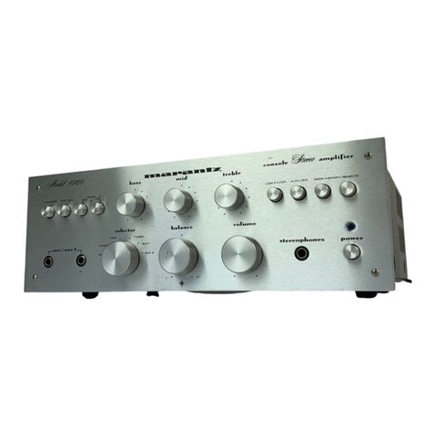
Marantz SM500DC User manual

SERVICE
MANUAL
st
+
sk
ak
baat
sh
af.
hb
«gh
wy
4
a
+
oa
manele
Shore
Foor
Molin,

MARANTZ
DESIGN
AND
SERVICE
Using
superior
design
and
selected
high
grade
components,
MARANTZ
Company
has
created
the
ultimate
in
stereo
sound.
Only
original
MARANTZ
parts
can
insure
that
your
MARANTZ
product
will
continue
to
perform
to
the
specifications
for
which
it is
famous.
Parts
for
your
MARANTZ
stereo
are
generally
available
within
72
hours
throughout
the
nation
via
a
toll-free
line
to
our
National
Parts
Depot
in
California.
The
sales
professionals
who
take
your
call
immediately
refer
to
their
own
desk
top
com-
puter
terminal
and
can
quickly
determine
the
availability
and
price
information
you
require.
If
for
some
reason,
your
order
should
exceed
our
available
stock,
we
usually
can
instantly
provide
an
alternate
replacement
part
or
current
delivery
infor-
mation.
When
the
order
is
placed
and
confirmed,
the
computer
simultaneously
generates
“hard
copy”
orders
at
the
distribution
center.
As
hard
copies
come
directly
from
the
computer
to
the
national
parts
depot,
your
requested
stock
is
assembled
and
prepared
for
shipment
and
placed
on
the
first
available
carrier
for
delivery
to
you.
,
ORDERING
PARTS
Phone
orders
will
eliminate
mail
delays,
and
we
encourage
the
use
of
this
method.
If
you
order
by
mail,
use
MARANTZ
parts
order
forms
which
are
available
from
our
National
Parts
Depot
located
at
the
following
address:
SUPERSCOPE
NATIONAL
PARTS
DEPARTMENT
20525
Nordhoff
Street
Chatsworth,
California
91311
Phone:
1-800-423-5108
1-213-998-9333
The
following
information
must
be
supplied
to
eliminate
delays
in
processing
your
order:
.
Complete
address.
.
Complete
part
numbers.
.
Complete
description
of
parts.
.
Model
number
for
which
part
is
required
(indicate
MARANTZ).
.
Account
number
(for
account
customers
only).
OPWN
=
Direct
consumers
will
be
provided
with
the
current
retail
prive
quotation
on
available
parts
in
order
to
advise
them
of
the
cost
of
the
parts
and
shipping.
OVERSEAS
PARTS
ORDERING
Parts
may
also
be
ordered
from
the
following
overseas
addresses:
U.S.A.
CANADA
AUSTRALIA
JAPAN
Marantz
Company,
Inc.
Superscope
Canada,
Ltd.
Marantz
Australia
;
Marantz
Japan,
Inc.
National
Service
Dept.
3710
Nashua
Drive
32
Cross
Street
3622
Kamitsuruma
P.O.
BOx
577
Mississauga
,
Brookvale,
NSW
2100
Sagamihara-shi
Chatsworth,
CA91311
Ontario,
Canada
L4V1M5
Australia
Kanagawa,
Japan
U.S.A.
.
EUROPE
;
Marantz
Europe
S.A.
Marantz
France
Marantz
Audio
U.K.,
Ltd.
Marantz
Germany
GMBH
326
Avenue
Louise
Bte
32.
+4
rue
Bernard
Palissy
193
London
Road
Max-Planck-Strasse
22
1050
Brussels
92600
Asnieres
Staines,
Middlesex
:
6072
Dreieich
Belgium
France United
Kingdom
West
Germany
Marantz
Belgium
Marantz
Svenska
A.B.
Marantz
Norske
A.S.
45
rue
Auguste
Van
Zande
Franzengatan
6
Refstadalleen
13
1080
Brussels
:
10425
Stockholm
Oslo
5
Belgium
Sweden
‘Norway
All
of
the
above
locations
are
fully
equipped
to
take
care
of
your
total
service
needs.
Because
various
countries
have
differing
configuration
requirements,
it is
necessary
that
you
contact
the
service
facility
in
your
particular
country.
In
the
event
that
there
is
no
service
location
listed
for
your
country,
please
contact
the
nearest
facility
for
the
necessary
assistance.

TABLE
OF
CONTENTS
SECTION
PAGE
TINFRODUCTIONS
cece
6
ce
ee
Se
Sa
ree
Seite
Senha
Wad
hence
le
dda
bo
wow
wwe
Shee
1
255
PAWEBOAR
D
seiscseccds
te
cacy
See
Sige
ev
oh
td
Sa
gcicah
sa
tal
eed
cas
a
cea
eee
ane
we
Att
ee
Boe
i
ees
an
died
1
3.
BLOCK
DIAGRAM
oo. cic
die
ne
sce
eee
eb
ie
cae
ee
dees
wa
bee
Ba
Ohba
ee
eels
we
Rama
1
4.
TEST
EQUIPMENT
REQUIRED
FORSERVICING
.........0.
0...
ccc
ccc
eee
eee
eee
ees
2
5.
ALIGNMENT
PROCEDURES
icicscacakiniee
dus
poate
ciao
tse
Maiko
aed
ber
oekeaan
eee
2
5.1
Idling
Current
Alignment
Procedure...
0.0.0...
000
cece
cece
eee
e
cece
ceeeeeeeuenesuuueunas
2
5.2
Power
Meter
Alignment
Procedure...
..
2...
cece
eee
eee
eee
e
ween
een
enneae
2
6.
DIAGRAM
AND
COMPONENT
LOCATIONS
.............
0...
ccc
cece
cece cece
eee
e
nen
eeeaas
3
6.1
Main
Amp
&
Power
Supply
Assembly
(P700)
Schematic
Diagram
and
Component
Locations
..............
3
6.2
Speaker
Switch
Assembly
(PS00)
Schematic
Diagram
and
Component
Locations
...................0-.
5
6.3
Headphone
Assembly
(PWO00)
Schematic
Diagram
and
Component
Locations
................
ores
5
6.4
Lamp
Assembly
(PZ00)
Schematic
Diagram
and
Component
Locations
.................c0ceeeuuees
5
7
EXPLODED
VIEW
AND
PARTSLIST
oi
acces
hisgenis
Sek Ewe
aedu
eee
e
ee
asad
ws
ewe
ROS
6
8..
ELECTRICAL
PARTS
LISS:
oé.5.0scseoes
alos.
g
Gu
GW
obo
ewietd
oho
Wa
ha
an
ew
Oeero
ee
Baran
ens
eo
aaks
12
9:
VOLTAGE.
CONVERSION
i
3505
cites
echoes
ob
Se
ene
Geb
va
ek
vib
tale!
ete
hee
elena Seana
ce
a
@svbatecaan
de
14
10.
TECHNICAL
SPECIFICATIONS.
...........
0.0.0.0.
ccc
ee
eee
ee
id
Sats
eS
Oe
aneeet
ve
15
TTASCHEMA
LG
DIAGRAM
os5
heciese
nic
es
oe
eh
eedas
o
paki
Wed
ha
SADE
oe
Lilie
bo
Ga
eaeeeke
16

MODEL
SM500
DC
STEREO
POWER
AMPLIFIER
SPARRO
Pa
Ne
Reid
RES
OS.
RR
ws.
$.
&
"eb
Ke
%.
1.
‘INTRODUCTION
This
service
manual
was
prepared
for
use
by
Authorized
Warranty
Stations
and
contains
service
information
for
the
Marantz
Model
SM500DC
Stereo
Power
Amplifier.
Servicing
information
and
voltage
data
included
in
this
manual
are
intended
for
use
by
knowledgeable
and
ex-
perienced
personnel
only.
All
instructions
should
be
read
carefully.
No
attempt
should
be
made
to
proceed
without
a
good
understanding
of
circuitry
operation.
The
parts
list
furnishes
complete
ordering
information.
Most
replacement
parts
should
be
ordered
from
the
Marantz
Company.
However,
a
simple
description
is
included
for
parts
which
can
be
obtained
locally.
3.
BLOCK
DIAGRAM
FEEDBACK
NETWORK
POSITIVE
PREDRIVER
DRIVER
BIAS
CIRCUIT
DIFFERENTIAL
INPUT
NEGATIVE
PREDRIVER
DRIVER
DC
SERVO
AMPLIFIER
PR
AR
REGIE
POSITIVE
LOAD
LINE
LIMITING
PROTECTION
CIRCUIT
NEGATIVE
2.
P.W.
BOARDS
As
can
be
seen
from
the
circuit
diagram,
the
chassis
of
Model
SM500DC
consists
of
the
following
units.
Each
unit
mounted
on
a
printed
circuit
board
is
described
with-
in
the
square
enclosed
by
a
bold
dotted
line
on
the
circuit
diagram.
1.
Main
Amp
&
Power
Supply............-
mounted
on
P.W.
Board
P700
2.
Speaker
Switch.
...
mounted
on
P.W.
Board
PSOO
3.
Head
Phone......
mounted
on
P.W.
Board
PWOO
4,
Lamp..........
mounted
on
P.W.
Board
PZ00
POWER
METER
POSITIVE
CIRCUIT
POWER
SPEAKER
PROTECTION
RELAY
HEAD
TO
RCHO——
||
PHONES
2
NEGATIVE
OWE,
SPEAKERS
SYSTEM
1
TO
RCH
SPEAKER
SYSTEMS
SYSTEM
2
TO
RCH

4.
TEST
EQUIPMENT
REQUIRED
FOR
SERVICING
This
table
lists
the
test
equipment
required
for
servicing
for
the
Model
SM500DC
Stereo
Power
Amplifier.
Item
Manufacturer
and
Model
No.
Distortion
Analyzer
Audio
Oscillator
AC
Voltmeter
Sound
Technology
Model
1700B
Use
Distortion
Measurements
Sinewave
and
squarewave
signal
source
voltage
measurements
(AC)
;
Tektronix
Model
T932
Oscilloscope
oa
Philips
Model
3232
Circuit
Tester
Waveform
analysis
and
trouble
shooting
and
ASO
alignment
Trouble
shooting
DC
Voltmeter
Fluke
Model
8000
“‘Digital’’
Simpson
Model
313,
Triplet
Model
801
Voltage
measurements
(DC)
AC
Wattmeter
Simpson
Modei
1379
Monitors
primary
power
to
amplifier
AC
Ammeter
Commercial!
Grade
(1
~
10
A)
Monitors
amplifier
output
under
short
circuit
condition
Line
Voltmeter
Simpson
Model
1359
Monitors
potential
of
primary
power
to
amplifier
,
Variable
Autotransformer
Superior
Electronic
Co.,
Powerstet
Model
116B-10A
Shorting
Plug
Output
Load
(8
ohms,
+0.5%
100
W)
Output
Load
(4
ohms,
+0.5%
100
W)
Use
phono
plug
with
600
ohm
across
center
pin
and
shell
Commercial
Grade
Commercial
Grade
Adjusts
level
of
primary
power
to
amplifier
Shorts
amplifier
input
to
eliminate
noise
pickup
Provides
8-ohm
load
for
amplifier
output
termination
Provides
4-ohm
load
for
amplifier
output
termination
Output
Load
Capacitor
(0.5
mfd)
Mylar
Provides
capacitive
load
for
instability
checks
AC
Power
Control
Box
Optional
Item.
Fabricate
in
accordance
with
Figure
1
Monitors
and
controls
primary
power
for
amplifier
Amplifier
Output
Load
Box
CL
Optional
Item.
Fabricate
in
accordance
with
Figure
2
Provides
various
amplifier
loads
and
can
monitor
shorted
output
5.
ALIGNMENT
PROCEDURES
5.1
Idling
Current
Alignment
Procedure
Where
to
be
adjusted:
R733
and
R734
Adjusted
value:
20
mV
(20
mA
ea.)
’
Procedure
1
With
the
input
of
the
set
placed
in
Open,
set
the
power
switch
to
ON.
2
Adjust
semi-fixed
resistance,
R733
and.
R734,
so
that
the
voltage
of
both
the
ends
of
R741
and
R742
may
become
20
mV
after
10
seconds.
5.2
Power
Meter
Alignment
Procedure
Where
to
be
adjusted
Lchannelee-<
Gees
atk eee
Ga,
ae
dee
eek
RX74
R:
channelnns
sh.
SSNS
ees
tele
eees
RX08
Procedure
1
Connect
the
load
resistance
892
to
the
speaker
ter-
minal
of
the
set.
2
Connect
the
1
KHz
from
SG
to
input.
3
Set
the
power
switch
of
the
set
to
ON,
increase
the
SG
output,
and
adjust
the
speaker
output
to
be-
come
50W
—
822
(20V).
4
Adjust
RX07
and
RX08
so
that
the
meter
may
indi-
cate
50W
(82).

DIAGRAM
AND
COMPONENT
LOCATIONS
6.
6.1
Main
Amp
&
Power
Supply
Assembly
(P700)
Schematic
Diagram
and
Component
Locations.
i
|
zoer.
logs
|
roar
\\7
O7nF
bE
ov
o—
ee
é
=
O
A0S/I+,
9|
6089
4
t
°|
O
[neteoerhca)
Aos/00z8
z08
Lx
4
rc
soey
AOS/L¥°0
AG2/
2%
90ND
OO!
OSzy¥
001
6b2y
\
AZZ
SINY
e220
(M1)
OL
(AD)49
"1
90x
a
AW
2200
10xy|4e'@-
—-XL2
10
Xa
(M1)
01
VV
sve
19°9
£ONY
rl
SONY
60ND
os!
6e2y
AGO,
2120
a'@
A9I/01
2029,
_3
<a
0Z1
6128
(6)
o
AEO-
AO
+
ba
is
LA
MO”
nog
roy
2020
2029
Os!
g02y
dozB
POLd
AGE
24144
AzLO-
NEP
pros
jJ—le
GIL
id
’
%)
ALO-
+
Seer
A0S/01
lot
Hy
:
1029
HH
7%!
|
ozo
AOS
/OL
~
$02)
ASI
.
Ay
Ft
Osi
4024
doze
€029
AN1ddNS
YAMOd
(AD
ABT
GOXe
:
do
1129
Pud
dWV
NIVW
WEE
L224
poLo
002d
[_
Wah
1228
—_—c
rrr
rr
rrr
ee
ee
om.

:
‘gore
9ozr
f
I I
ie
eozr
iy
zozr
0
oO
"AdAL
‘o)
AdONNSLAOSZ—WIL
|
AWA
3T8!SN4
NN
dvd
S39v
Ida‘
NOLLNALLV
>
"3SNd
AdAL
SWS
HLIM
AINO
390
1d3a‘CavZVH
90Xu
VAVNYS!_VWSNEA0SZ—-VI
|
Jala
LSNIVOV
NOILISLOdd
GANNILNOD
40s‘
NOLLNVO
sozcr
toxr
£0xr
coxr
O
OO
9
wy
6089
90ND
+
coxa
AR
t
“A
TS
+
:
.
”
-—{—
—
—}—
SzZ0
t2zo
£zL0
i
—_—v—
Spey
prey
A
—w—
tOND
SONY
cond
ZOND.
90NY
OND
ann
Yon

6.2
Speaker
Switch
Assembly
(PS00)
Schematic
Diagram
and
Component
Locations
4
He
Oo
oO
SSOl~1
Ssoi-2
6.3
Headphone
Assembly
(PW00)
Schematic
Diagram
and
Component
Locations
|
Pwoo
|
aw
0
|
Ave
330(1W)
[Avr
330(1W)
|
i
6.4
Lamp
Assembly
(PZ060)
Schematic
Diagram
and
Component
Locations
eee
are
[
VZOI
VZ02 VZO3 VZ04 VZO5
vzo6
/\\
|
JZOI
JZO2
5
[A
A
A
Ds
j
eS
2S
sZOr
YF213HO0010
vzo1
©
vzo2
(0)
vzo3
©
vzo4
©
vzos
©
vz06
JZO02

7.
EXPLODED
VIEW
AND
PARTS
LIST
@
[C01-99]
Front
Panel
002B
006B
011B
©
(U)
for
U.S.A.
®
(N)
for
Europe
®
(A)
for
Australia
©
(F)
for
Japan
1232063400
|
Front
Panel
Assembly
208H154060.|
Knob,
Push
Switch
123Z063410
|
Front
Panel
Assembly
51300306B0
|
P.H.
Tapped
Screw
P3x6
1232063010
|
Escutcheon,
Front
Panel
51300306B0
|
P.H.
Tapped
Screw
P3x6
1232063110
|
Escutcheon,
Front
Panel
403H067010
|
Cap
403H063020
|
Escutcheon
208H259010
|
Bushing,
Push
Switch

e@
[C02-99]
Lid.
(Top
and
Bottom
Cover)
PART
NO.
208H257010
51260408Z0
51260408U0
2991259010
1232257010
403H057010
51280308B0
DESCRIPTION
Lid,
Top
Cover
B.T.
Screw
B4x8
B.T.
Screw
B4x8
Bushing
Lid,
Bottom
Cover
Leg
B.H.
Tapped
Screw
B3x8
PART
NO.
51280308B0
213H118020
213HO56020
2932861110
2578861010
e@(U)
for
U.S.A.
e
(N)
for
Europe
e
(A)
for
Australia
e
(F)
for
Japan
DESCRIPTION
B.H.
Tapped
Screw
B3x8
Spacer
Buffer
Label
Top
Cover
Label
Bottom
Cover

@
[C03-99]
Rear
Panel
1232160010
1232160020
1232160030
51280308U0
51280308U0
51280308U0
51280308U0
51280308U0
51704059B0
1455259030
= =
SP
BNONNA
CP
BNNNA
PK
BNNNA
SK
2|
2
51420308T0O
OO9E
2|
2
51280308U0
0O12E
|
1/1]
1]
1
|
2112265010
014E
1]
1
4581861010
9511101070
Bracket
Rear
Panel
Bracket
"
Bracket
ns
B.H.
Tapped
Screw
B3x8
B.H.
Tapped
Screw
B3x8
B.H.
Tapped
Screw
B3x8
B.H.
Tapped
Screw
B3x8
B.H.
Tapped
Screw
B3x8
Spec.
Set
Screw
Bushing
O.C.H.
Tapped
Screw
O3x8
B.H.
Tapped
Screw
B3x8
Indicator
Label
Label
UL
OO8E
(A.N)
OO5E
OO2E
aa
e(U)
for
U.S.A.
e
(N)
for
Europe
e
(A)
for
Australia
e
(F)
for
Japan
PART
NO.
DESCRIPTION
FS10400500
FS10200800
FS10400600
YJ08000310
YJ08000290
YJ08000300
YJ04000560
YLO3010250
BY05080010
YP04000590
YC0O1900070
2C01805030
ZC02006030
YC01800190
Fuse
4A
250V
Fuse
T2A
250V
Fuse
4A
250V
Jack,
Fuse
Holder
Jack,
Fuse
Holder
Jack,
Fuse
Holder
Jack,
AC
Outlet
Terminal,
GND
Voltage
Selector
Plug,
Inlet
A.C.
Power
Cord
A.C.
Power
Cord
A.C.
Power
Cord
A.C.
Power
Cord

@
[P01-99]
Front
Chassis
and
General
Parts
004G
021G7
O10F
$001
010E
(NA)
6001
014G
015G

e(U)
for
U.S.A.
e(N)
for
Europe
e
(A)
for
Australia
e(F)
for
Japan
Q’TY
PART
NO.
DESCRIPTION
‘i
aes
PART
NO.
DESCRIPTION
403H120010
|
Insulator
1
|
141
|
1232160090
|
Bracket
2
|
2]
2
|
51280306B0
|
B.H.
Tapped
Screw
B3x6
1/1/1417
|
1232105010
|
Front
Chassis
3]
3]
3
|
51260308B0
|
B.T.
Screw
B3x8
4) 4] 4] 4]
51100306A9
|
B.H.M.
Screw
B3x6
1|1
|
1
|
1232160080
|
Bracket
1/1)
1/7)
1
|
1232160120
|
Bracket
2
{212
|51280306B0
|
B.H.
Tapped
Screw
B3x6
3}
3]
3]
3
|
51280308B0
|
B.H.
Tapped
Screw
B3x8
2|2]2
|
51280306B0
|
B.H.
Tapped
Screw
B3x6
1]1}11]
1
|
213H274010
|
Reflector
2|
2)
2)
2
|
1232160070
|
Bracket
1|141
|
1232267010
|
Heat
Sink
2}
2)
2]
2
|
51280308B0
|
B.H.
Tapped
Screw
B3x8
33}
3
|
51280306B0
|
B.H.
Tapped
Screw
B3x6
3
|
3]
3]
3
|
213HO56010
|
Buffer
2
{2
|
2
|51100310A9
|
B.H.
M.
Screw
B3x10
2/2]
2]
2)
213H118010
|
Spacer
4|4
|
4
|51480310A9
|
F.
Washer
Screw
F3x10
1/1/11]
1
11232160100
|
Bracket
1}141
|
¥TO2020210
|
Terminal
4/4]
4]
4
|
51280308B0
|
B.H.
Tapped
Screw
B3x8
1|1]1
|
YT03040190
|
Terminal
2/2)
2]
2
|
51280306BO
|
B.H.
Tapped
Screw
B3x6
1
|111
|
¥YT03040190
|
Terminal
1/1]11]
1
|
2912259020
|
Bushing
71 }1
11
|¥J01001400
|
Jack,
Headphone
1|1]1]1
|
1232160040
|
Bracket,
Left
1/4/11]
1
|
1232160050
|
Bracket,
Right
DK18103530
|
Ceramic
0.01uF
1/1111]
1.]
1232160060
|
Bracket,
Center
1}1
DK18103840|
Ceramic
0.01uF
4/41{4]
4]
51280306B0
|
B.H.
Tapped
Screw
B3x6
1
|DK18103850;
Ceramic
0.01ynF
4|4j]|
4]
4
|
51280306B0
|
B.H.
Tapped
Screw
B3x6
1/1/11]
1
|123Z160110
|
Bracket
TS19617010
|
Power
Transformer
4/4]
4]
4
|
51260408U0
|
B.T.
Screw
B4ax8
1/1
TS19617020
|
Power
Transformer
2/|2|
2)
2
|
51280306B0
|
B.H.
Tapped
Screw
B3x6
1
|
TS19617030
|
Power
Transformer
2
|
2] 2]
2
|
51280306B0
|
B.H.
Tapped
Screw
B3x6
1]1)1]
1
|
213HO56030
|
Buffer
1}
1/1
|
1M12255010
|
D.C.
Meter
SP01010420
|
Push
Switch,
Power
1/1
SP01010390
|
Push
Switch,
Power
1
|
SP01010430
|
Push
Switch,
Power
10

@
{H01-99]
Packing
Materials
010S
;
/
OOST
(F)
001S
002T
OO3T
(U)
004T
(A)
013S
@
(U)
for
U.S.A.
e@(N)
for
Europe
e
(A)
for
Australia
e
(F)
for
Japan
=|
1232801010
|
Packing
Case
1232801020
|
Packing
Case
1232801030
|
Packing
Case
001H809010
|
Cushion
9090909040
|
Polyethylene
Sheet
2918107350
|
Sheet
2918107390
|
Sheet
9526019010
|
Serial
No.
Card
9526019060
|
Serial
No.
Card
9526019030
|
Serial
No.
Card
125Z851010
|
Instructions
1252851310
|
Instructions
1252851110
|
Instructions
1232851020
|
Instructions
1232851320
|
Instructions
9631000110
|
Guarantee
Card
2818854020
|
Guarantee
Card
1232856010
|
Circuit
Diagram
2205851040
|
Instructions
2976851040
|
Instructions
2225813010
|
Envelope
9631000090
|
Guarantee
Card
2976813020
|
Enveiope
9650000030
|
S.
Station
Card
9526019040
|
Serial
No.
Card
2731821010
|
Silicagel

@
(U)
for
U.S.A.
e@(N)
for
Europe
@
(A)
for
Australia
e
(F)
for
Japan
8.
ELECTRICAL
PARTS
LIST
PART
NO.
DESCRIPTION
PART
NO.
DESCRIPTION
DESIG.
july]
ale
P700-MAIN
AMP
&
POWER
SUPPLY
CIRCUIT
BOARD
YK213H1310]
P.W.
Board,
Main
Amp
&
Power
Supply
2Z213H1310
|
P.W.
Board
Assembly
GD05152140
1.5kQ
GD05152140
1.5kQ
GD05391140
3902
GD05391140
3902
GD05433140
43kQ
GD05433140
43kQ
GD05392140
3.9kQ
GD05392140
3.9kQ
GD05124140
120kQ
GD05124140
120k.
P700-CAPACITORS
EA10605030
|
Elect
10uF
50V
EA10605030
|
Elect
10uF
50V
DK16821300
|
Ceramic
820pF
+10%
DK16821300|Ceramic
820pF
+10%
EA10605030
|
Elect
10uF
50V
EA10605030
|
Elect
.
10nF
50V
EQ10601630
|
Elect
10uF
16V
£Q10601630
|
Elect
10uF
16V
EQ10601630
|
Elect
10uF
16V
EQ10601630
|
Elect
10uF
16V
ee
ee ee
re
ee
eG
soe
ewe
ean
mo
or
Seer
oo ee
oe
os
a
ee
ee
eG
GD05473140
47kQ
GD05473140
47kQ.
GD05103140
10k2
GD05103140
10k2
GD05153140
15kQ
GD05153140
15kQ
GD05333140
33kQ
GD05333140
33kQ
GD05473140
47kQ
GD05473140
47kQ
DD15100300
|
Ceramic
10pF
+5%
DD15100300
|
Ceramic
10pF
+5%
DD15220300
|
Ceramic
22pF
+5%
DD15200300
|
Ceramic
20pF
+5%
EA10605030
|
Elect
1OuF
50V
EA10605030
|
Elect
10uF
50V
DK16101510
|
Ceramic
100pF
+10%
DK16101510
|
Ceramic
100pF
+10%
DK16101510
|
Ceramic
100pF
+10%
DK16101510|
Ceramic
100pF
+10%
ee
ee
er
eo
ee
ee
ee
ee
ee
ee
ee
ee
ee
a
a
ee
ey
GD05820140
82Q
GD05820140
822.
RA05010050]
Trimming
4702
(B)
RA05010050]
Trimming
4702
(B)
GD05102140
1kQ
GD05102140
1kQ
GD05820140
822
GD05820140
822
—
GD05151140
1502
GD05151140
1502
DF17473520
|
Film
DF17473520
|
Film
EA10705030
|
Elect
EA10705030
|
Elect
EA10705030
|
Elect
0.047uF+20%
0.047uF+20%
100nF
SOV
100uF
SOV
100uF
SOV
ee
ee
ee
ee
ee ee
ee
ee
ee
ee
ee
a
ee
re re
Ce
ee
ee
NE10472050
0.472
EA10705030
EB82805010
EB82805010
Elect
Elect
Elect
100uF
50V
8200uF
50V
8200uF
50V
NE10472050
GA05100030
GA05100030
0.472
102
102
GA05100010
102
GA05100010
102
NFO2101140
NFO2101140
NFO2101140
NFO02101140
EA10602530
|
Elect
10uF
25V
EA10602530
|
Elect
10uF
25V
DK18103560
|
Ceramic
DK18103560
|
Ceramic
DK18103560
|
Ceramic
0.01nuF
+80,—20%
DK18103560|
Ceramic
0O.01pF
+80,—20%
EA10505030
|
Elect
1pF
50V
0.01nF
+80,—20%
0.01uF
+80,—20%
Pe
ee
enon
nna
Pee
ooo
eo
oo
eo
er
ee
ee
ee
ee
ey
See
eo
oe
oo
or or
GD05472140
GD05472140
GD05472140
GD05472140
GD05103140
DF16223300
|
Film
DF
16223300
|
Film
0.022uF210%
0.022uF+10%
=a
32
a
oe
=o
5444
=o
444
ee
eee
rey
P700-RESISTORS
(All
Resistors
are
5%
and
“*W)
GD05682140
GD05682140
GD05682140
GD05682140
GD05473140
GD05473140
GD05821140
GD05821140
GD05821140
GD05821140
GD05104140
100k2
GD05104140
100k2
GD05331140
3302
GD05331140
3302
GD05473140
47kQ
GD05473140
47kQ
GD05151140
1502
GD05151140
1502
GD05152140
1.5kQ
GD05152140
1.5kQ
Sew
ee
eo
oor
or
er
Ee
ee
ee
ee
ee
ee
ee ee
ee
ee re
ee
ee
re
12

PART
NO.
DESCRIPTION
PART
NO.
@
(U)
for
U.S.A.
e
(N)
for
Europe
e
(A)
for
Australia
e@
(F)
for
Japan
DESCRIPTION
pa
ee
Ce
ne
Se
CD
—
=
a
re
ee
ee
see
eo oo
a
em
oa
=a
oe
oo
eo
see
oo
moana
a
er
oy
pane
ee
ee
es
ee
sey
eae
ee
ree
ee
ee
pe
ee
ee ee
ee
ey
|e
oo
a
oa
we
em
oo
a=
ee
pane
er
ee
ree
ee
OD
—
pare
ee
ee
ee
ee
a
er
Ce
ee
so
2
9
oo
eo
ne
=
oe
SB
ee
ooo
em
ona
= =
pa
re
ee re
ee
ey
=aewo
non
nn
ma
ee
ee
ee
ee
se
ow
os
eo om
or
or
os
=a
ae
GD05823140
GD05823140
GD05223140
GD05473140
GD05274140
GD05183140
GD05183140
GD05333140
GD05563140
GD05222140
GD05222140
GD05134140
GD05273140
GD05273140
GD05103140
GD05103140
GA05182010
GA05182010
RA05010050
RA05010050
HT322592F0
HT322592F0
HT319802A0
HT319802A0
HD20010010
HD20010010
HD20010010
HD20010010
HC10019020
HT111232C0
HT111232C0
HV00006080
HV00006080
HT326312C0
HT326312C0
HT325912B0
HT325912B0
HT111112B0
HT111112B0
HT326812B0
HT326812BO
HT111412B0
HT111412B0
HD20015030
HD20015030
HD20015030
HD20015030
HD2001
1290
HD20011290
HD20011290
HD20011290
HD30013010
HD30013010
HD20015030
82k2
82kQ
22k.
47kQ
270k
18k2
18k2
33kQ
56kKQ
2.2kQ2
2.2kQ
130k2
27kQ
27kQ
10kQ
10k2
1.8kQ2
1W
1.8kQ2
1W
Trimming
4702
{B)
Trimming
4702
(B)
P700-SEMICONDUCTORS
Transistor
2SC2259(F,
G)
Transistor
2SC2259(F,
G)
Transistor
2SC1980(R,
S)
Transistor
2SC1980(R,
S)
Diode
182076
Diode
182076
Diode
182076
Diode
1S$2076
IC
AN6552
Transistor
2SA1123(R,
S)
2SA1123(R,
S)
STV-3H
STV-3H
2SC2631(R,
S)
2SC2631(R,
S)
28C2591(Q,
R)
28C2591(Q,
R)
28A1111(Q,
R)
28A1111(Q,
R)
28C2681(R,
OQ)
Transistor
Varistor
Varistor
Transistor
Transistor
Transistor
Transistor
Transistor
Transistor
Transistor
2SC2681(R,
Q)
2SA1141(R,
Q)
2SA1141(R,
Q)
DS-1350
DS-1350
DS-1350
DS-1350
$3V-20
$3V-20
$3V-20
Transistor
Transistor
Transistor
Diode
Diode
Diode
Diode
Diode
Diode
Diode
Diode
Zener
Zener
Diode
$3V-20
HZ15-2L
HZ15-26
DS-135D
Bo
oe
ee
ae
ew
aw
oe
a
a
ay
ee
ee
ee
ey
ae
ee
ee
ey
ae
ee ee ee
ee
ny
a
ee
ry
=o
Soe
oe
een
a
oo
ord
HT309451
00
HT309451
00
HT107331Q0
HT10733100
HD20010010
HD20010010
HD20010010
HD20010010
HD20010010
HD20010010
HD20010010
HD20010010
HC10042050
HD20010010
HC10041050
LL23915120
LL23915120
LY20240190
FS10100500
FS10100800
FS10100600
YJ08000170
YJ08000270
YJO08000170
Y
J08000270
YK213H1320'
ZZ213H1320
SP02020520
YK213H1330
Z2Z213H1330
Y¥J01001400
YU03700240
GA05331010
GA05331010
YF213HO0010
Z2Z213HO0010
IN10080510
IN10080510
IN10080510
1N10080510
IN10080510
IN10080510
28C945(Q)
2SC945(Q)
2SA733(Q)
2SA733(Q)
182076
1$2076
1$2076
182076
1S2076
1$2076
Transistor
Transistor
Transistor
Transistor
Diode
Diode
Diode
Diode
Diode
Diode
Diode
1$2076
Diode
1$2076
Ic
TA7317P
Diode
1S2076
IC
TA7318P
P700-COILS
Coil,
Choke
Coil,
Choke
Relay
P700-MISCELLANEOUS
Fuse
1A
250V
Fuse
TIA
250V
Fuse
1A
250V
Jack,
Fuse
Holder
Jack,
Fuse
Holder
Jack,
Fuse
Holder
Jack,
Fuse
Holder
PSOO-SPEAKER
SWITCH
CIRCUIT
BOARD
P.W.
Board,
Speaker
Switch
P.W.
Board
Assembly
PSOO-SWITCH
Push
Switch,
Speaker
PWOO-HEADPHONE
CIR-
CUIT
BOARD
P.W,
Board
Head
Phone
P.W.
Board
Assembly
PWO00-MISCELLANEOUS
Jack,
Head
Phone
Jumper
Lead,
3Px700mm
3302
1W
3302
1W
PZO0-LAMP
CIRCUIT
BOARD
P.W.
Board,
Lamp
P.W.
Board
Assembly
PZ00-LAMPS
Lamp
Lamp
Lamp
Lamp
Lamp
Lamp
100mA
100mA
100mA
1O0O0mMA
100mA
100mA
(w01-99)
(701-99)
(X01-00)
Assembly
and
Wiring
Adjustment
Correction
13

11.
SCHEMATIC
DIAGRAM
ee
_—_—_—_—_—_
—-
-—ooooooo
=n
a
ec
ss
Se
-O-
BOTTOM
VIEW
Q703,0704
R721
47k
PEAK
MEATER
(633)
I:EMITTER
Q711,
Q712
&
i
‘
2:COLLECTOR
Q715,0716
i
mee
cm
yd
pad
ov
R72?
S38
]
kta
Cae
3:
BASE
QNO1,QNO2
Pp
i
MAIN
AMP.
and
“039
6)
QNO3,QNO4
POWER
SUPPLY.
R719
120k
el
+
ooo
$R725
:
SIDE
VIEW
|
r
15k
RXO2
O
[Oo]
Q717,0718
mney
27k
ov
|
1:
BASE
Q719,Q720
i
SOT
TOEV-B?
RXO4
Oz
x07.
hal
2:COLLECTOR
0721,0722
10k
OV
yen
3:EMITTER
Q723,0724
RxX03
é
R709
RTI
ere!
a
10k
a
Oz
RXO8
°
Q7Il
43.6V
.
470-8
H
43.2V
(yy
Lav
J
RXO}
RO.
1
238
|
tt
XK
)
AV
27k
i
C703
.2y
\QNO!
Q725
:
|
i
820p
if
C73
42V
RNII
i
R707
Tz
p
82k
renew)
+
&
ov
a
|
[ewoo
|
|
c7ol
Q701
ae
70)
|
=
ON
-O
uwol
701
lo/SOV
8
|
LNOI
|
E
HEAD
:
+3
—w—
—-|-
O
MAIN
IN
QQ
Rre®
m2
RNIS
RNIG-18k
5,0
|
|
ZNRTSI
33001)
O
PHONE
i
(L)
47k
0
RNI4
270k
ONI4
==
|
|
i
O7I3
5
a7k
y
{
|
O
wWol
O
R745
/\,
LJ__y4
[NRT82
330(1W)
;
i
oA
lo
(iw)
}
4
ane
‘aE
deg
|
A2V
1OV
.
:
Q715|
—
lonor
ZN
©)
43
>
-/,
2Y
CNO3
-O.6V
OV
Q727
a
|
:
H
'
-.2V
[4700p
x
Q7I9
Q723
+
|
OO)
0
c719
Q)
QO)
28
se
"0
:
Sonos
!
|
R737
TT
oop
-~45.6V
-45.6V
zs
Zz
cNnd7
22/25V
i
82
0.47/50V
SPEAKER
|
6
SYSTEM!
Se
OO
(ce
L
R
||
oe
Yi
(el
ea
eas
|
!
Ee
:
:
¢704
ee
eee
[-O
SPEAKER
seh
Z\R747
100
©
SYSTEM
2
R708
{50
Q807
C706
a3.3V
10759
c702
Q702)
|
ov
4
3702
10/50V
oy
oF
MAIN
IN
(GQ)
(R)
=
6
|.
°
R706
Poay
>
S
aS
FBO!
ss
ACIOOV
og
S
50/60Hz
=
o
wool
0.8V
2
o
Jo2)
Z\
_
AC
UNSWITCHED
fe.7V
34.2v]
200W
MAX
GRY
O
caoul
GRN
Oe
C712
10p
O
Dy
|
For
(F)
VERSION
R722
47k
ieee
em
SIDE
VIEW
1:
BASE
2:
COLLECTOR
Q701
R720
I20k
a
Cr
-
rr
r—-
—
S
—
3:
EMITTER
Q702
Oe
Ap
‘Osev
/\6001
0.017400
|
Z\co01
0.01/125v
|
4:COLLECTOR
BP
A
ZN
5:BASE
|
|
&
|
123465
|
|
|
SIDE
VIEW
—_—_—_—.
ax
QNni3
SS
QXO1
Q70!,0702
Q7039
Q715
,Q716
Q721,0722
Q80i°UVQ804
=QN03,
QNO4
a2
|
es
|
HT322592F0
HC10019020
HT326312CO
-
HT326812B0
-HD20011290
=:
HT107331Q0
HOV
a8
2SC2259(F,G)
AN6552
2S8C2631(R,S)
2SC268I(R,Q)
S3V-20
2SA733(Q)
i20v
|
z¢
|
iT
9
Q703,0704
Q711,Q712
Q717,Q718
Q723,0724
Q805,Q806
QNI3
28ON.
TOP
VIEW
HT319802A0
HTI232C0
HT325912BO_-
HTII1412BO_
HD30013010
+
HC
10042050
8
5
2SC
1980IR,S)
2SAl123(R,S)
28C2591(0,R)
2SAII141(R,Q)
4715-2
TA7317P
|
|
Q709
Q705V.0708
Q713,Q714
Q719,Q720
97250728)
=QNOI,QNO2
=
QO
or
(U.C)
VERSION
QNOS“LOQNI2,QNI4
~Hvoo006080
HT3HI11I2BO
Q807
HT309451Q0
HCI0041050
f|
|
For
(U,C)
paras,
esha
4
HD2001I00i0
STV3H
2SAIN1IIN(Q,R)
HD200I5030
25¢945(Q)
TA7318P
1S2076
;
DS-135D
Note
on
safety:
The
parts
marked
with
A
are
important
parts
on
the
safety.
Components
and
wiring
are
subject
to
change
for
modification
without
notice.
16
Please
use
the
parts
having
the
designated
parts
number
without
fail.
17

9.
VOLTAGE
CONVERSION
To
convert
the
unit
to
a
different
power
source
voltage,
change
the
position
as
illustrated
in
the
drawing
below.
CAUTION:
DISCONNECT
POWER
SUPPLY
CORD
FROM
AC
OUTLET
BEFORE
CONVERTING
VOLTAGE.
DO
NOT
DISASSEMBLE
THE
VOLTAGE
SELECTOR
ABSOLUTELY.
~
~—
ON
eee cee
(A)
Versions
(N)
Version
NOTE
ON
SAFETY:
THE
PARTS
MARKED
WITH
A\
ARE
IMPORTANT
PARTS
ON
THE
SAFETY.
PLEASE
USE
THE
PARTS
HAVING
THE
DESIGNATED
PARTS
NUMBERS
WITHOUT
FAIL.
10.
TECHNICAL
SPECIFICATIONS
AUDIO
SECTION
POWER
OUTPUT
PER
CHANNEL
AF
OHMS:
DINGAUKAZ
3
oe
er
Soh
ec
hee
Sern
wk
aN
Sits
wld
weenie
Wit
wera
ee
RA
SES
SE
Sel
85
W
OHMS
RMS:
VKAZ
oc
bcc
Roce
6b
ae
se
he
elie
se
en
GE
ees
ae
eee
ee
ae
a
ee
Be
80
W
BSOHMS:DINEWKHZ.
2
dec
elise
are ore
Se
sro
tebb.
8
oes
ore
tal
Sahay
ara
ante elee
a
salienSs
Soe
ISLE
Ma
oe
BASS
ave
Serva
es
wa
bala
tan
65
Ww
8
OHMS
RMS
1kHz.............
20.02
ee
eee
eee
a
Se
seheg
ae
tl
yet
gta
eared
mi
Eas
bila
dno
tacaw
a”
athac
at,
ok
asigieaee
60
W
TOTAL
HARMONIC
DISTORTION
AT
RMS
8OHMS
.....
2... 0...
.
ee
ee
ee
ees
0.03%
1.M:
DISTORTION
icsscb
uc:
(EG
od
Be
Be
SG
eens
Bana
See
ase
eH
fa
geen
g
ete,
Wis
Gaei
Gael
gs
BOR
Slab
aes
0.03%
DAMPING
FACTOR
8
OHMS
(1
kHz)
2...
0...
ee
eee
80
Input
Sensitivity/Impedance
..
0...
ee
ee
eee
1.5V/32
kohms
Frequency
Response
(+0/—O0.3dB)
..
0.2...
ccc
ee
ee
tne
eee
eee
es
5
Hz—50
kHz
Signial-to-Noisé
Ratios:
o:s.5.
vc
serine
Roe
we
Ee
Wed
SF
aA
ere
weet
a
ee
ark
e
BS
eee
Se
Be
lea
Qi’
S
Siena
120
dB
GENERAL
Power
Requirements.
2.50,
20
Nisae
etn
cae
ee
wae
eas
Ga
SINGS
eee
ah
ae
ae
8
220
V
AC,
50
Hz
(E
and
N
versions
are
featuring
an
external
voltage
selector
for
use
on
other
voltages.
Other
versions
can
be
converted
by
a
qualified
technician
to
operate
on
240V.}
Power
Consumption
(at
Rated
Output,
Both
Channels
Operating)
............
200
eee
ee
eee
eee
220
W
Dimensions
Pariel:
Wichthis.
4%
sock
tS
ve
eee
es
Satie
ike
ak
wa
arid.
Save
Wehandite
er
tice
Baca
tne
nnn
auly
tener
eal
ete
ty
ater
eta
416
mm
Parvel
Heights:
cic
arte
on oe
kts
were
cae
el
rd
ewe
ae
Pee
UR
RRS
Reentiate
oe oe
aa te
73
mm,
Depthy
ei
ovis:
heey
el
hek
oe
eee
be
SAS
adapted
ants
dh
B
Gosd
Sete
phew
hha
tie
a
ee
Babes
302
mm
Weight
Unit
atone...
2...
cee
ee
eee
cee
Seach
He
eee
eae
MAS
i
woe igh
os
Ea
Dole
ahace
Wiese
aia
at
eee
ae
ere
7.9
kg
Specifications
and
appearance
are
subject
to
change
for
modification
without
notice.
15


Printed
in
Japan
»
¢
.
ran
ERR
e@e
Teas
en
@Z.,;
213H855010
CR}
1981/2
Table of contents
Other Marantz Amplifier manuals

Marantz
Marantz 1072 User manual

Marantz
Marantz MM8003 User manual

Marantz
Marantz SR7300 User manual

Marantz
Marantz PM551 User manual

Marantz
Marantz 74 PM16/02B User manual

Marantz
Marantz PM-94 User manual

Marantz
Marantz PM-17SA User manual

Marantz
Marantz 4100 User manual

Marantz
Marantz PM5004 User manual

Marantz
Marantz PM-10 User manual

Marantz
Marantz PM7005 User manual

Marantz
Marantz PM8004/K1SG User manual

Marantz
Marantz AV8805 User manual

Marantz
Marantz PM8200 User manual

Marantz
Marantz MA-9S2 Manual

Marantz
Marantz PM4200 User manual

Marantz
Marantz AV8003 User manual

Marantz
Marantz PM310 User manual

Marantz
Marantz 8B Stereophonic User manual

Marantz
Marantz PM5004 Installation and operating instructions