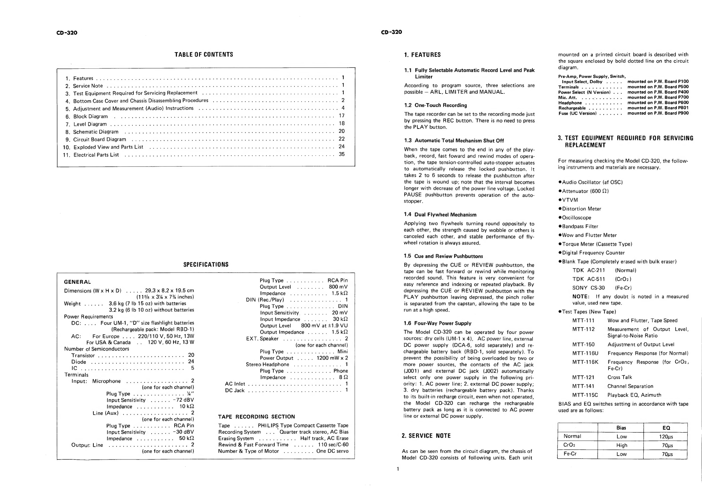
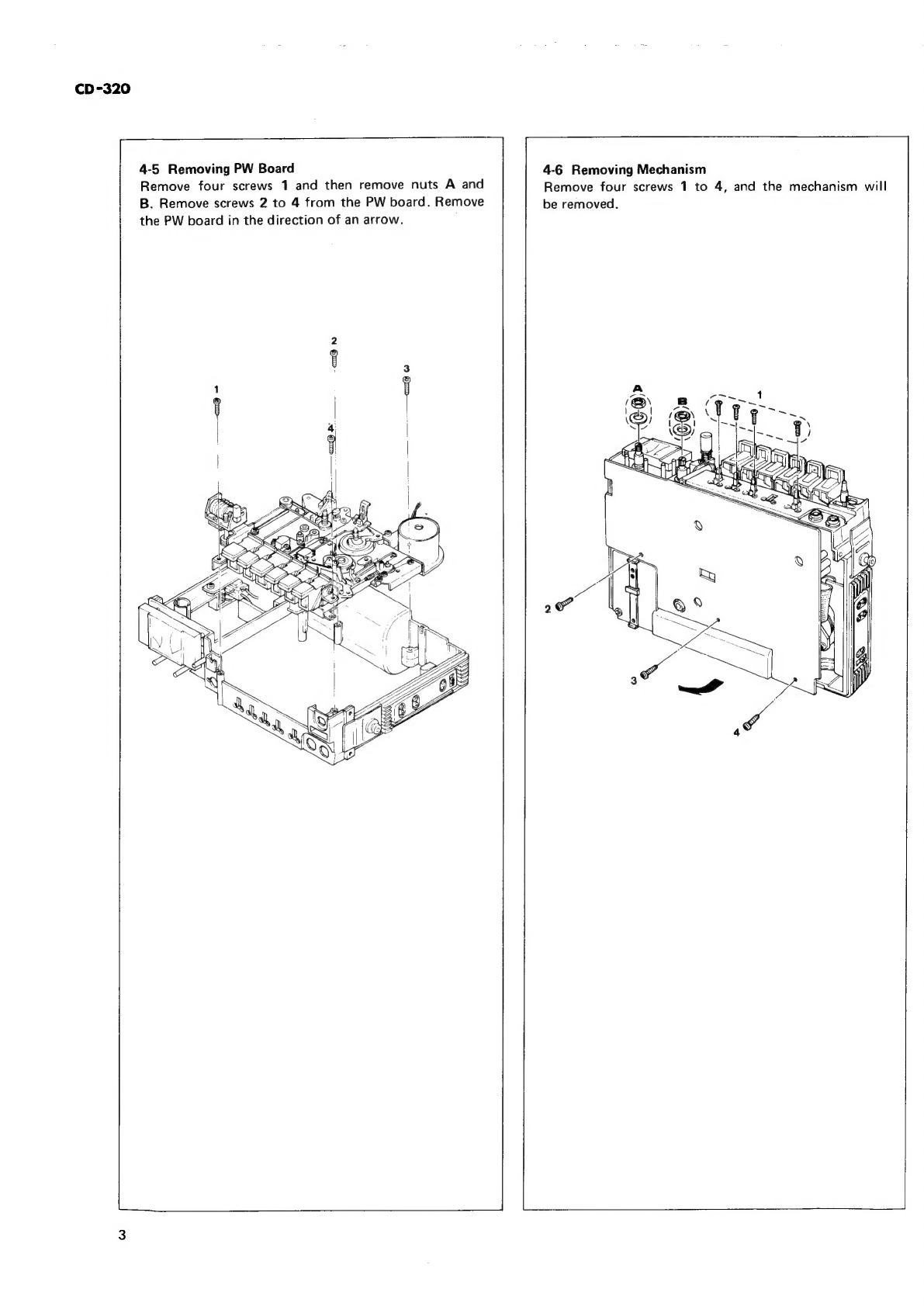
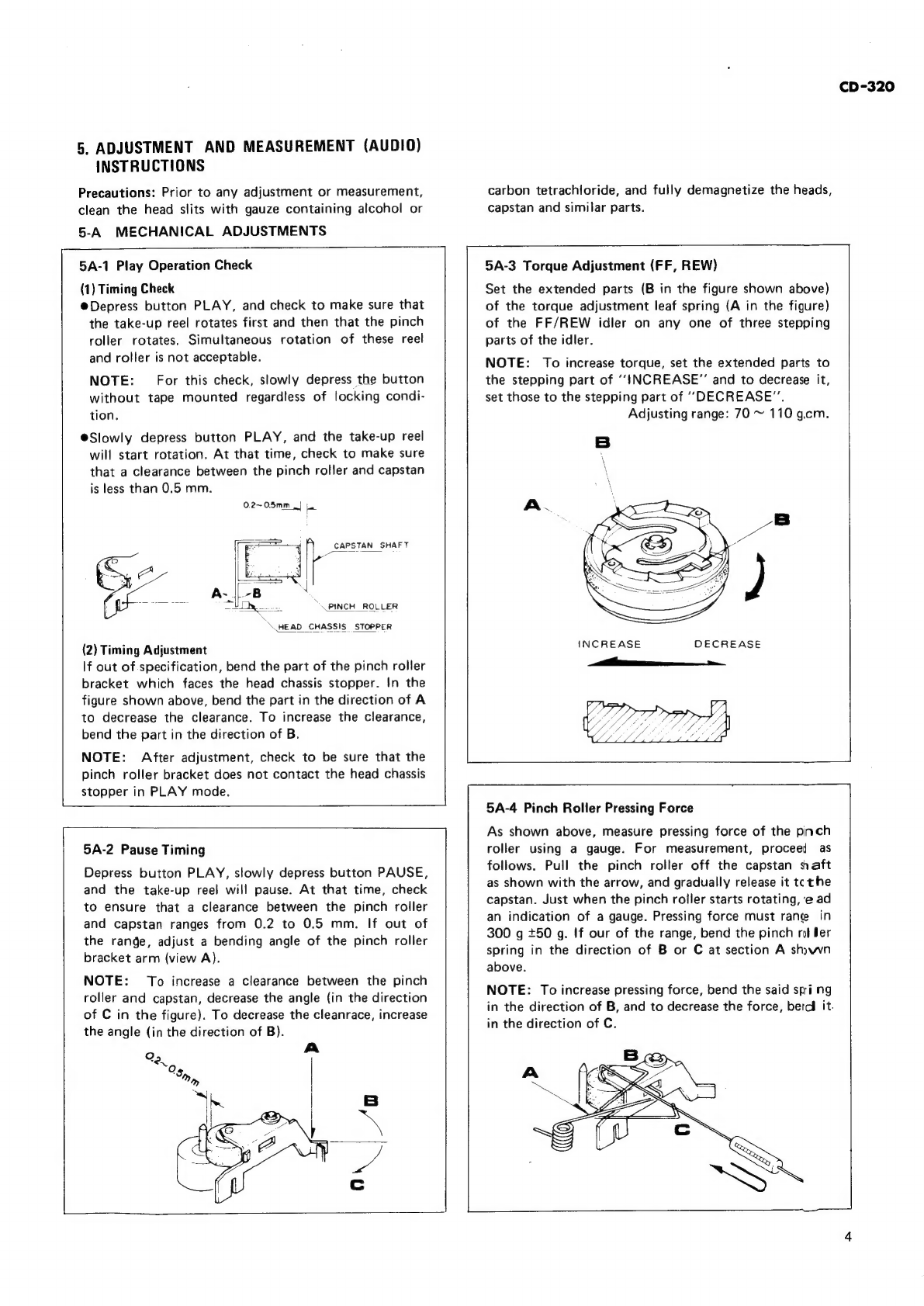
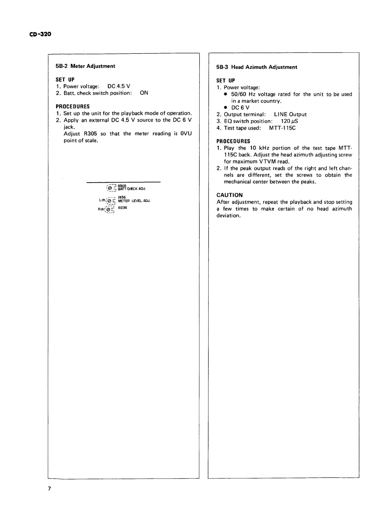
Marantz SUPERSCOPE CD-320 Mounting instructions
Other Marantz Cassette Player manuals

Marantz
Marantz PMD505 User manual

Marantz
Marantz SD-4051 User manual

Marantz
Marantz SD4050 User manual

Marantz
Marantz PMD101 User manual

Marantz
Marantz cp430 User manual

Marantz
Marantz SUPERSCOPE CRS-2204 User manual

Marantz
Marantz PMD211 User manual

Marantz
Marantz PMD510 User manual

Marantz
Marantz Professional PMD520 User manual

Marantz
Marantz SD530 User manual

Marantz
Marantz Professional PMD520 User manual

Marantz
Marantz SUPERSCOPE CD-320 Mounting instructions

Marantz
Marantz 5025 User manual

Marantz
Marantz PMD201 User manual

Marantz
Marantz SD-4051 User manual

Marantz
Marantz PMD511 User manual

Marantz
Marantz PMD201 User manual

Marantz
Marantz PMD420 User manual

Marantz
Marantz 5220 User manual

Marantz
Marantz CP230 User manual


Popular Cassette Player manuals by other brands


Sony
Sony CFS-B15 - Am/fm Stereo Cassette Recorder operating instructions

Sony
Sony WMFS220 - Portable Sports AM/FM Cassette... operating instructions

Aiwa
Aiwa HS-TA21 operating instructions

Sanyo
Sanyo MCD-ZX700F Service manual

Aiwa
Aiwa CS-P77 Service manual

Sony
Sony Pressman TCM-465V operating instructions