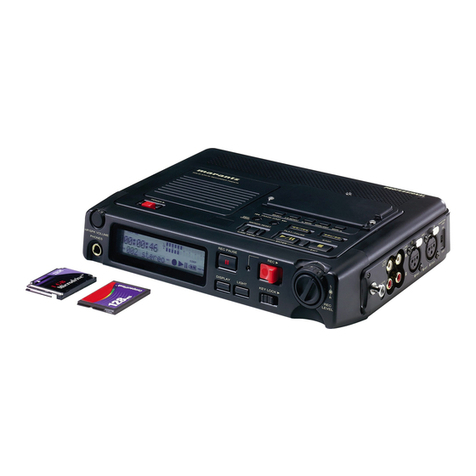
Marantz PMD420 User manual

www.SteamPoweredRadio.Com
..
MARANTZ DESIGN AND SERVICE
Using superior design and selected high grade
components,
MARANTZ
company
has created
the
ultimate
in
stereo sound.
Only
original
MARANTZ
parts
can in$ure
that
your
MARANTZ
product
will
continue
to
perform
to
the
specifications for
which it
is
famous.
Parts for
your
MARANTZ
equipment
are generally available
to
our
National Marantz Subsidiary
or
Agent.
ORDERING
PARTS:
Parts can be ordered either by mail
or
by telex. In
both
cases, MARANTZ
part
number has
to
be specified. If
you
order
by
mail, fulfil
MARANTZ
order
forms.
MARANTZ
S.
A.
MARANTZ
NATIONAL
PARTS DEPARTMENT
. EUROPEAN PARTS DEPARTMENT
2, Avenue Leopold
Ill
8-7120
PERONNES-lez-BINCHE
BELGIUM
TWX:
57589
SEPLT 8
I
20525
Nordhoff
Street
Chatsworth, California 91311
Phone: 1-800-423-5108
Phone:
1~998-9333
&718
The following information must be supplied
to
eliminate delays
in
processing
your
order:
1. Complete address
2. Complete
part
numbers and quantities required
3.
Description
of
parts
4.
Model
number
for which part
is
required
5. Way
of
shipment
6. Signature: any
order
form
or
telex
must
be signed otherwise such
part
order
will be considered as null and void.
PARTS ORDERING:
Parts may be ordered from
the
following addresses:
MARANTZ
S.A.
European
Parts
Department
2,
Avenue Leopold Ill
B-7120 Peronnes-lez-Binche
Belgium
MARANTZ
DENMARK
Bregneredvej 132b
3460
'.
Birkered
Denmark
MARANTZ
SVENSKA
A.
B.
Svartviksvagen 56
Traneberg
Bromma
Sweden
MARANTZ
S.A.
326
Avenue Louise
Bte
32
1050 Bruxelles
Belgium
MARANTZ
FRANCE
4
Rue
Bernard Palissy
92600
Asnieres
France
EUROPE
MARANTZ
AUDIO
U.K.
LTD
Unit 15/16
Saxon
Way
Industrial Estate
Moor
Lane
Harmondsworth UB7
OLW
Great Britain
MARANTZ
GERMANY
G.M.B.H.
Max Planckstrasse 22
6072
Dreieich 1
Germany
AUSTRALIA
MARANTZ
AUSTRALIA
PTY
19
Chard
Road
Brookvale, NSW 2100
Australia
MARANTZ
AUSTRIA
Ge.M.B.H.
25
Franz Lisztgasse
2
380
Perchtoldsdorf
Austria
MARANTZ
ITALIANA
S.p.A.
Via
Monte Napoleone
10
20121 Milano
Italy .
U.S.A.
MARANTZ
COMPANY,
INC
..
National Service
Dept
PO
. Box
577
Chatsworth,
CA
91311
U.
S.A.
MARANTZ
BELGIUM
45
Rue
Auguste
Van
Zande
1080 Brussels
Belgium
MARANTZ
NEDERLAND
B.V.
Wagenmakersweg 3
3449
HV Woerden
Netherlands
JAPAN
MARANTZ
JAPAN,
INC.
35-1,
7-chome, Sagamiono
Sagamihara-shi: Kanagawa
Japan
All
of
the
above locations are fully equipped
to
take
care
of
your
total
service needs. Because various countries have differing
configuration requirements, it
is
necessary
that
you
contact
the
service facility in
your
particular
country.
In
the
event
that
there
is
no service location listed for
your
country,
please,
contact
the
nearest facility for
the
necessary assistance. ·
NOTE-FOR
U.S.A.
ONLY
In
case
of
difficulties,
do
not
hesitate
to
contact
the
Technical
Department
at
abovementioned address.
Parts for
your
MARANTZ stereo are generally available within
72
hours
throughout
the
nation via a toll-free line
to
our
National Parts Depot in California. The sales professionals
who
take
your
call immediately refer
to
their own desk
top
computer
terminal and can quickly determine
the
availability and price information
you
require. If, for some reason, your
order
should exceed
our
available
stock,
we usually can instantly provide an alternate replacement
part
or
current delivery
information. When
the
order
is
placed and confirmed,
the
computer
simultaneously ge,nerates
"hard
copy"
orders at the
distribution center.
As
hard copies come directly from
the
computer
to
the
national parts
depot,
your
requested stock
is
assembled and prepared for shipment and placed
on
the
first available carrier
for
delivery
to
you.
Phone orders will eliminate mail delays, and we encourage
the
use
of
this
method.
If
you
order
by
mail, use
MARANTZ ' •
parts
order
forms which are available from MARANTZ NATIONAL PARTS DEPARTMENT.
...
.._
..
.._.._.Z®
•

www.SteamPoweredRadio.Com
.
I
'
I
L
•
•
•
TABLE
OF
CONTENTS
SECTION
PAGE
INTRODUCTION . . . . . . . . . . . . . . . . . . . . . . . . . . . . . . . . •. . . . . . . . . . . . . . . . . . . . . . . . . . . . . •. . . 1
1.
2.
3.
4.
5.
SHOCK, FIRE
HAZARD
SERVICE
TEST.............................................
1
P.W.
BOARDS
...................
:-
. . . . . . . . . . . . . . . . . . . . . . . . . . . . . . . . . . . . . . . . . . . . . . 1
TEST EQUIPMENT FOR SERVICING . . . . . . . . . . . . . . . . . . . . . . . . . . . . . . . . . . . . . . . . . . . • . . . 1
MECHANISM
AND
CIRCUIT DESCRIPTION
.....................................•...
2
4.1
MIC
AMP
and Attenuator
••
-
•••••••.•••••••••••••.•••••
, , , • • • • . • • • • • • • . . • • • . . . • • . •
2
4.2 Auto
PLAY
and Automatic Rewind Stop • . • • • • • • • • • • • . • • • • • • . • . . . • . . . . . • • . • • • • • . . • • • • •
2
4.3 Auto Stop
..•...•.•••••••••••••.••••
, • • • • • • • • • . . • • . . . . • . . . . • . . . . • • . • . • . . • . . .
2
4.4 Pitch Control . . . . . • • . . . . . • • . • • • • • . • . • . . . . . • • • . . • . . . • • • . • . . . . • . . • . . • • . . • • • • • • • • 2
ELECTRICAL ADJUSTMENTS
....................................................
3
5.1 Head Azimuth Adjustment . . • • • . . . . . . . . . . • . . . . • . . • . . . • • • • . . • • . . • • • • • . • • • • • • • • • • • • •
3
5.2 Tape Speed Adjustment . . • . . . . . . . . . . . • . . . . . . . • . . . . . . . . . . . . • . . • . . . . . . . . • . . . • . . • . . .
3
5.3 Playback Equalizer Adjustment . . . . • . . . . • • . . • . . . • . . . . . . . . . . . . • • . . . . • . . . • • . • • • . • • • • • •
3
5.4 Playback
Level
Adjustment . • • . . • • . • • . • • . • . . . • . . • • . • • . • . • . • . . • • • • • • . • • . • • • • • • • • • • •
3
5.5
Level
Meter Adjustment
...••...•••..•...•.....•.•.........••••••.•••••••••••
, • • •
4
5.6 Playback Noise Measurement • • • . • • • • • . . . . . . . . . . . • . • • • . • • • • • • • • • • • • • • . • • • . • • • • • • • • •
4
5.7
MPX
Filter Measurement • • • • • • • • • • • • . • . • . • . . • • . . • • • • • • • • . • • • • . • • • • • • • • • • • • • • • • • • •
4
5.8 Record/Playback
Level
Adjustment . . • . • . • • . • . • . . . • . . . • • • • • • • • • • • • • • • • • • • • • • • • • • • • • • • 4
5.9 Record/Playback Frequency Response Adjustment . . . . . . . . . . . • • • • • • • • • . • • . • • • . . • • . • . . • • • • 4
5.10 Alignment Points . . • . . . . • . . . . • . . . . . • . . . • . . . . . • . . • . . . • . . • . • • • . • • . . • . . • • • . • . . • • • •
5
6.
DIAGRAMS . . . . . . . . . . . . . . . . . . . . . . . . . . . . . . . . . . . . . . . . . . . . . . . . . . . . . . . . . . . . . . . . . . . . 6
6.1 Block/Level Diagrams • . . . • • . . . • . • . . • • . . . . . . . . • • . • . • • . . • . • • • • . • • • • • • • • • • • • • . . • • • •
6
6.2 Chip Component Locations • • • • • • . . • • . . . . . . . . . . . . . . . . . • . . . • . • • • • • • • • • • • • • • • . • • • • • . 7
6.3
Wiring
Diagrams . • • • • . • • • • • • • • • • • • • • . • . . . . . • . . • • . . • • • • • • • • • • • • • • • • • . • • • . • • • • • •
8
7.
EXPLODED VIEW
AND
PARTS LIST
...............................................
10
•
8.
ELCTRICAL PARTS LIST
........................................................
•
16
9.
TECHNICAL SPECIFICATIONS
....................................................
22
10.
SCHEMATIC DIAGRAM
.......................
.
........
...
....................
•
..
23

www.SteamPoweredRadio.Com
MODEL PMD420/CP230 STEREO CASSETTE RECORDER
INTRODUCTION
This service manual
is
prepared for
use
by Authorized
Warranty Station and contains service information for
Marantz
Stereo
Cassette
Recorder.
Servicing information and voltage data included in this
manual
are
intended for
use
by the knowledgeable and ex-
perienced technician only. All instructions should
be
read
carefully. No attempt should
be
made to proceed without a
good understanding
of
the operation
of
the
Cassette
Recorder.
The parts list furnishes information by which replacement
parts
may
be
ordered from the Marantz Company.A simple
description is included for parts which
can
be
usually ob-
tained through local suppliers.
1.
SHOCK, FIRE HAZARD SERVICE TEST:
CAUTION:
After
servicjng this appliance and prior
to
re
•
turning
to
customer,
measure
the
res
istance between
either primary AC cord connector pins (with
unit
NOT
connected
to
AC mains and its Power switch ON),
and
the
face
or
front
Panel
of
product
and
controls
and
chassis
button.
Any
resistance measurement
less
than 1 Megohms should
cause
unit
to
be
repaired or corrected before AC power
is
applied, and verified before return
to
user/customer.
Ref.
UL
Standard NO. 1270.
Para
66. 3. D (Mandatory
Test after servicing Electrical Appliances, effective 7•1-83).
2.
P.W.
BOARDS
As can
be
seen from the circuit diagram, the chassis
of
your
Cassette
Recorder consists
of
the following units.
Each
unit
mounted
cm
a printed circuit board
is
described
within the square enclosed by a bold dotted line
on
the cir-
cuit diagram.
1. Rec/Play
Amp
.......
mounted on
P.W.
Board
P100
2.
Bias
OSC
...........
mounted on
P.W.
Board
P200
3.
Mic
Switch
.........
mounted on
P.W.
Board
P300
4.
L.E.D.
.
...........
mounted on
P.W.
Board
P400
5. Rec/Play
Sub
.
.......
mounted on
P.W.
Board
P500
6.
Mecha
Control
.......
mounted on
P.W.
Board
P600
7.
Control
Switch .
......
mounted on
P.W.
Board
P700
8.
Light
.............
mounted on
P.W.
Board
PSOO
9.
Mic
Mode
..........
mounted on
P.W.
Board
P900
3. TEST EQUIPMENT REQUIRED FOR
SERVICING
For measuring
or
checking
your
Cassette
Recorder, the
following instruments
and
materials
are
necessary.
•
VTVM
• Audio Oscillator
(AF
OSC)
• Attenuator
(600
n)
• Oscilloscope
• Bandpass Filter
(1
kHz)
•
IEC
A-Curve Filter
•
Wow
and
Flutte.r
Meter
• Torque Meter (Cassette Type)

www.SteamPoweredRadio.Com
i
I
~
•
•
•
•
•
• Digital Frequency Counter
• Distortion Meter
• Blank Tapes (C9mpletely
erased
with bulk eraser)
TDK
AC-212
(Normal)
TDK
AC-512 (Special/CrO2)
TDK
AC-712 (Metal)
NOTE:
If
any
doubt
is
noted
in
a
measured
value,
use
new
tape.
•
TestTapes
MTT-111
MTT-112
MTT-1128
MTT-150
MTT-256
MTT-356
MTT-121
MTT-141
(New Tape)
Wow
and
Flutter, Tape
Speed
Measurements ofOutput Level
Signal-to-Noise Ratio
Adjustment of Output Level
Frequency Response (for Normal)
Frequency Response (for Special/
Cr02,
Fe-C2
and
Metal)
CrossTalk
Channel Separation
4.
MECHANISM
AND
CIRCUIT
DESCRIPTION
4.1
MIC AMP
and Attenuator
The basic circuit for
the
mic amp
is
a low noise, positive-
phase amplifier utilizing OP Amp. It
is
used
iri
place
of
an
attenuator
to
modulate
the
amplifier gain
without
the
need
for an
attenuator
between
the
input
signal. Gain adjustment
takes place inside
the
NF
loop
of
the amplifier. When 0dB
occuring, a HIGH signal enters by way
of
CD
and
@
at
111,
0211,
O112and
0212
and maximum gain
is
achieved.
At
-15d8
the
level becomes HIGH only
at
CD
setting
both
0111
and
0211
to
ON, with maximum gain
at
-15d8.
At
-30d8,
the
level
at
both
CD
and
@
simultaneously be-
comes
LOW,
with maximum gain
at
-30d8.
With this sys-
tem, compared
to
when
the
attenuator
is
on,
the
input
noise
is
fixed and lowering of
the
signal-to-noise ratio,
which occurs when
the
attenuator
is
ON,
is
prevented.
0 0
2
4.2 Auto PLAY and Automatic Rewind Stop
With SC03 set
to
ON
during PLAY,
the
rewind
button
will
lock when pressed. When
counter
reaches
999,
the
rewind
lock releases and the PLAY operation resumes.
In
this
condition, both CUE and REVIEW
buttons
do
not
operate
and
both
buttons
are locked. Also, when
the
FF
button
is
pressed and locked
in
place,
the
lock releases when the
counter
reaches
"900"
and the PLAY
mode
is
entered. When
the
tape
has finished winding
in
both
modes before the
counter
reaches
the
respective positions,
the
AUTO STOP
function and
all
buttons
are released. Also when
the
RE-
WI
ND
button
alone is locked,
the
tape
rewinds and rewind
stops when
the
counter
reaches
"999".
The same applies
for fast toward operation which stops
at
"900".
When the
counte
r
is
between
"900
" and
"999".
both
REWIND and
FF
bottons
do
not
lock.
4.3 Auto Stop
The AUTO STOP function which detects
the
end
of the
tape
is
carried
out
by hole
IC
(OM20).
The
signal from
OM20
is
added
to
the
pin
©of
OM19,
while
the
auto
stop
duration
is
designated inside
OMl
9. The time it takes for
the
auto
stop
function
to
activate after the tape stops,
is
determined
in
CM08. At this time TE
is
TE
=
75 X
CMOS
(µF)mSec, while
TW
is
TW
=
30
X CM07 (µF)
mSee
as
long
as
the
auto
stop
function
is
operating.
When
it does
not
shut
off the first time, TE--Tw--TE-
-TW
is
repeated until it shuts
off
.
4.4 Pitch Control
The pitch control
is
used
to
vary
the
tape speed for play-
back operation.
Du
ring recording, it
is
automatically set
to
the
RC01
center position by S105-2.
Rec
-Play

www.SteamPoweredRadio.Com
5.
ELECTRICAL
ADJUSTMENTS
Precautions
for
Adjustment
and
Measuremen
_t
1.
Before playing back
the
test
tape, thoroughly demag-
netize
the
heads, capstan and similar metal parts using
an erase, as
the
test
tape-recorded
tone
is
easily erased.
2. Do
not
place
the
test
tape
on
any measuring instrument.
3.
Do
not
put
the
test
tape
near a place where
the
eraser
is
used.
4.
Method of Demagnetization: Turn
the
eraser power
..
switch
on
at a position far away from
the
heads. Bring
the
eraser close
to
the
heads, capstan and
other
parts
to
be demagnetized, and move it
up
and down four
or
five
times
to
demagnetize. Slowly separate
the
eraser far
away from
the
parts, and
turn
the
power switch off.
5.
Do
not
use any magnetized adjusting tool.
If
necessary,
demagnetize with a bulk eraser from time
to
time
in
the
course
of
each adjustment.
6.
Do
not
turn
semi-fixed resistor
or
coil more
than
needed.
7. Measure speed and wow and flutter
in
the
normal
operating state.
8.
Do
not
apply locking bond excessively.
9. Check
the
line voltage and
the
output
of low frequency
oscillator 2 -3 times a day
to
see
if
they
are set
as
specified.
5.1
Head Azimuth Adjustment
1. Play
the
test
tape MTT256 back. Adjust the head azimuth
adjusting screw for maximum VTVM reading.
2. If the peak levels
of
the
left and right channels are
different set
the
screws
to
obtain
the
mechanical
center
between
the
peaks.
3. After adjustment, repeat
the
playback and
stop
settings
several times
to
confirm no azimuth deviation.
4. After adjustment, lock
the
screws with bond.
5.2
Mode: Playback
Test Tape
MTT-256
14kHz
~
Unh
Tape
Speed
Adjustment
VTVM
1. Play
the
3kHz signal
of
the
test
tape
MTT·111 back.
2. Adjust
the
adjusting resistor (RM05)
on
the
P600
P.W.
Board so
that
counter
readings are between
2990
-
3010Hz.
Mode: Playback
Test Tape
MTT-111
3 kHz
Unit
Line
Output
Frequency
Counter
I
000000
1
3
5.3
Playback
Equalizer
Adjustment
1. Adjust
the
tape
selector switch
to
NORMAL.
2. Play
the
315Hz signal
of
the
test
tape
MTT-256 back.
The VTVM
at
0dB.
3. Play
the
12.5kHz signal of
the
test
tape
back. Confirm a
frequency response
of
Oto
ldB
in
reference
to
the
315Hz
signal level.
5.4
Then, play
the
12.5kHz signal back.
Set
the
tape
selector
to
CrO2, Metal. Confirm
the
12.5kHz signal readings
at
-4.5dB, ±1dB.
Mode: Playback
Test Tape
MTT-256
14 kHz
Playback
Level
Adjustment
VTVM
ldl
1.
Adjust
the
Tape Selector Switch
to
NORMAL and
turn
the
NR
switch
OFF.
2. Play
the
test
tape MTT-150 back. Adjust R110(L) and
R210(R) so
that
the
voltage
of
OA02
@pin
and
@pin
is
100mV.
In
this operation, make sure
the
voltage
of
LINE
OUT
reads 550mV +
ldB.
NOTES:
1.
Proceed
both
for
the
night
and
left channels in
the
same
way.
2. For details refer
to
"Playback equalizer
adjustment".
Mode:
Palyback
Test Tape
MTT-150
0A02
@@
Pin
5.5 Level Meter Adjustment
VTVM
ldl
1. Adjust
the
Tape Selector Switch
to
NORMAL and
turn
the
NR
switch OFF.
2. Play
the
test
tape
MTT-150 back. Adjust R128(
L)
and
R228(R)
at
+3dB Level Meter reading.

www.SteamPoweredRadio.Com
•
..
•
•
•
5.6
Playback
Noise
Measurement
1.
Set
the
selector switch
to
NORMAL and
NR
switch
to
OFF.
2. Play back
the
blank
tape
and make sure
that
the
noise
volume
is
below 2mV when
the
REC LEVEL Knob
is
set
to
both
maximum and minimum.
NOTES:
1. Perform measurements when
the
power hum
is
at
mini·
mum.
2. Perform measurements under conditions where induc-
tion
noise will
not
affect measurements.
5.7
MPX Filter Measurement
1.
Adjust
the
Tape Selector Switch
to
NORMAL.
2.
Put
the
blank
tape
in
the
cassette holder, and set
the
recording conditions. (Dolby NR
"ON",
MPX
"ON"
positions)
3.
Add
a 1kHz
-20dB
signal
to
LINE
IN
. Adjust
the
Rec.
Volume
knob
.
to
0dB Level Meter reading.
4.
Set
the
input
signal
at
19kHz ±10Hz. Adjust T101 (L)
and T201 (R)
to
the
minimum level.
Mode:
record
AFOSC TONE: 1 kHz, 100mV
VTVM
ldl
Unit
Line Input Line Output
5.8 Record/Playback
Level
Adjustment
1.
Set
the
tape
selector switch
to
NORMAL.
2. Insert
the
AC-212
test
tape
in
the
cassette holder and
set
the
specified recording
condition
(LINE OUT:
350mV)
.
3. Adjust R119(L) and R219(R)
to
the
same level as
the
monitoring level when
the
tape
is
played back
after
rewinding.
4.
As
for CrO2/METAL tapes, make measurements with
the
AC-512 and AC-711
test
tapes as described above.
5.9 Record/Playback Frequency
Response
Ad-
justment
[NORMAL]
1.
Set
the
tape selector switch
to
NORMAL. (with Dolby
NR
"ON"
and
MPX
"OFF")
4
2. Insert
the
AC-212
test
tape
in
the
cassette holder and set
the
recording conditions.
Attenuate
from
550mV
to
25dB on Line
Out
with
the
attenuator
and record
at
1KHz and 10KHz
on
an unrecorded section
of
the
tape.
3.
Rewind
the
tape
and adjust CB01 (L) and CB02(R)
so
that
the
level for 1KHz and 10KHz
is
brought
within
±0.5dB for playback.
4.
After
making these adjustment, record and playback
at
1KHz, 10KHz and 12.5KHz. Make sure results comply
with
the
following diagram.
NR
•oFF•
C,,..~O-H_z
_____
,..!._
3
_d_e_10""'~.Jl•
12.5KHz
NR
•oN•
-----~t-3-dB~l'~dB
250Hz O
~•
I
KHz
12.5KHz
[CtO2 l
1.
Set
the
tape
selector switch
to
CrO2 •
2. Insert
the
AC-512
test
tape
in
the
cassette holder and
set
the
recording conditions.
Attenuate
from
550mV
to
25dB
on
Line
Out
with
the
attenuator
and record
at
1kHz, 1
Ok
Hz, 12.5kHz and 15kHz
on
an unrecorded
section
of
the
tape.
3. Rewind
the
tape
and adjust CB01 (
L)
and CB02(R) so
that
the
level for 1kHz and 1
Ok
Hz
is
brought
within
±0.5dB
for
playback.
4.
After
making these adjustments, record and playback
at
1kHz, 10kHz, 12.5kHz and 15kHz. Make sure results
comply
with
the
following diagram.
NR
3d8
5d8
BdB
250Hz
15KHz
-~13_dB-,7J5dB
250Hz
IOK~H
z 12.5KHz

www.SteamPoweredRadio.Com
6.2
Chip
Component
Locations
.~
....
~
·
:.J
i(-)
--
I . j 2\ .
-~
..
_ ' '
-!""
u
·.
-~~
~
(..,i
"
U;r,<E.~"
~ -
•~~~
.
-·
~
-~
'..J
~
.
- . :
-__,
L ,
LkrJ
f"',)
~
I C ~ ;
o-t:,
- .
0 0
a >
' . '
-
::=====;:==.:~
.
-
' \~)
' 0
0 _-
~
,;a -A
r-
~ ' 2
•
})
9
..,
lfll '
(._
~~
/J
\~ -
~-
•ol,
\t~
ai
,'
~__)>
. .ill_
~==~
-
41
7
·,
•
,o

www.SteamPoweredRadio.Com
[METAL]
1.
Adjust
the
Tape Selector Switch
to
METAL.
2. Load
the
test
tape
AC-
711 into cassette holder. Perform
measurements
as
with CrO2, and make sure
they
con-
form with
the
Chart
in
right.
NOTE:
Adjustment points for NORMAL, CrO2, METAL are
common
with CB01
(L)
and CB02(R).
5.10 Alignment
Points
5
3d8
250Hz
15KHz
__
_.._13_dB--~
'5de
250Hz
IOK~
12
.5KHz

www.SteamPoweredRadio.Com
6.
DIAGRAMS
6.1
Block/Level
Diagrams
• [RECORDING MODE] LINE
OUT
f:
1KHz
0A02
MPX
Jl03
FILTER a
DOLBY
MIC
q
BUFFER
MIC
@
JI05
LINE
IN
©
Jl02
(dBV)
+3
8
..
• 0
►
-10
-20
-20
-30
-40
-50
~
•
-60
-70.
[PLAYBACK MODE]
JI02
/
MTT-150
•
400Hz
200nwb/m
0A02
HEAD
PHONE
DOLBY '
(£
RIIO
JI05
(
dBV)
0
-5
-10
-20
-30
-40
-50
~
•
-60
-70
6

www.SteamPoweredRadio.Com
•
•
•
•
7. EXPLODED VIEW AND PARTS LIST
[C01-99) FRONT PANEL AND GENERAL PARTS
REF.
Q'TY
DESIG. PART NO. DESCRIPTION
u
N
A
p
0028
1 1 1 1 153T064020
Case
Front
0068
1 1 1 1 153T154500 Knob
Rec
Volume
(L)
(K)
0098 1 1 1 1 153T154510 Knob
Rec
Volume
(R)
(K)
012B 1 1 1 1 153T154030 Knob Monitor Volume
0138 1 1 1 1 153T154040 Knob Batttlight
0148 1 1 1 1 153T154050 Knob Limiter
017B 1 1 1 1 153T265010 Indicator Front
Case
0248 1 1 1 1 153T005010 Clamper
Rec
Volume
(R)
0458 4 4 4 4 51102606SO B.H.M. Screw
051B 1 1 1 1 153T251010
Badge
(MARANTZ)
0558 1 1 1 1 153T303030 Mask (A)
0568 1 1 1 1 153T303040 Mask
(B)
001F 1 1 1 1 153T104020 Retainer
Level
Meter
002F 1 1 1 1 153T160050 Bracket Top
Case
003F
1 1 1 1 153T160060 Bracket Top
Case
(LI
004F
1 1 1 1 153T160070 Bracket Top
Case
(R)
008F 1 1 1 1 153T104070
Retainer
P.W.B
+
Volume
009F 1 1 1 1 153T113010 Stud P.W.B.
013F
4 4 4 4 153T118010 Spacer
016F
2 2 2 2 5130260880
P.H.
Tapped Screw P2.6x 8
016F
3 3 3 3 5157260680 P. Tapped Screw
P2.6x6
017F 1 1 1 1 5130030880
P.H.
Tapped Screw
P3
x 8
q -
P200
REF.
O'TY
DESIG.
u N
A
p
018F 1 1 1 1
019F 3 3 3 3
N001
N002
10
.----
PIOO
/ 1
.
i.
015F
0
002F
PART NO.
5157260480
5130030680
iM31040010
iM31040020
l
'
,
r,
i '
• (Ul:for
USA
/;
•
(Nl
:for
Europe
[
• (Al:for
AUS1rllll
• (Pl:for
PX
DESCRIPTION
P. Tapped Screw
P2.6x4
P.H.
Tapped Screw
P3x6
V.U. Meter Left
V.U. Meter Right

www.SteamPoweredRadio.Com
A
'01)8
straia
...
[C02-99] MAIN
CASE
AND GENERAL
PARTS
REF.
Q'TY
DESIG.
PART
NO
.
DESCRIPTION
u
N
A
p
001B
1 1 1 1
153T064010
Case
Top
0038 1 1 1 1
153T257010
Lid
BattE!fY
0048
1 1 1 1
153T257020
Lid Control
0058 1 1 1 1
153T257030
Lid Cassette
0158
3 3 3 3
153T154060
Knob Slide Switch
0168
2 2 2 2
153T154070
Knob Pitch,Sias
Fine
0188
1 1 1 1
153T265020
Indicator Control
0196 1 153T053090 Cover Top
0198
1 1 1
153T053030
Cover Top
0208
1 153T053080 Cover
Bottom
0208
1 1 1
153T053020
Cover Bottom
021B 1 1 1 1
153T305010
Magnet Top Case
0228
1 1 1 1
153T063010
Escutcheon Control Cover
0238
1 1 1 1
153T060010
Cl
inger Control Cover
0258
1 1 1 1
153T007010
Strip
0266
1 1 1 1
153T153500
Hinge (K)
0298
1 1 1 1 64002500RO
RG
Ring,
E
0308
1 1 1 1
153T115090
Spring
031B 1 1 1 1
153T153020
Hinge Cassette Cover
0328
1 1 1 1
153T112380
Shaft
0338
1 1 1 1
153T104500
Retainer (K)
0368
1 1 1 1
153T104040
Retainer
037B 1 1 1 1
153T112370
Shaft Control Cover
0398
1 1 1 1
153T107010
Shaft Top Cover
040B 2 2 2 2
153T055010
Collar
Top
Case
041B
1
1 1 1 153T120010 Insulator Bottom
Case
0428
2 2 2 2
5106170450
P.H
.M. Screw
P1
.7 x 4
0438
2
2
2 2 51302606UO
P.H
.M. Screw P2.6x 6
044B 4 4 4 4
5184020450
F.H
.M. Screw
F2x4
0478
5 5 5 5
51842607S0
F.H.M. Screw F2.6x 7
11
• IU):for
USA
•
IAl:for
Aua1r
...
• (N):for Europe • IP):
for
PX
REF.
O'TY
DESIG
. PART NO.
DESCRIPTION
u
N
A p
048B 3 3 3 3
5184260550
F.H.M. Screw
F2.6x
5
0498
1 1 1 1
4581861010
Label
0528
1 1 1 1
153T861010
Label
0548
4 4 4 4
153T303020
Mask IA)
0588
1 1 1 1
153T303060
Mask
IB)
0598
2 2 2 2
5104031859
F.H.M. Screw
F3x
1.8
061B 5 5 5 5
5110260650
B.H.M. Screw B2.6 x 6
OOSF
1 1 1 1
153T160080
Bracket Mecha + Top
Case
006f
1 1 1 1
153T104050
Retainer Top Case
007F 1 1 1 1
153T104060
Retainer Top Cover
om=
1 1 1 1
153T129010
Terminal +
BattE!fY
011F 1 1 1 1
153T129020
Terminal+
BattEIIY
012F 1 1 1 1
YL11010090
Terminal -Battery
014f
1 1 1 1 51062605AO P.H.M. Screw
P2.6x
5
017F 6 6 6 6
5130030880
P.H.Tapped Screw
P3x
8
02~
1 1 1 1
251T274010
Reflector
021F 1 1 1 1
153T115100
Spring
022F 1 1 1 1
5130030680
P.H
.Tapped Screw
P3x6
023F 2 2 2 2
5130030880
P.H
. Tapped Screw
P3x
8
024f
2 2 2 2
4220005030
Clamper
025F 1 1 1 1
153T303080
Mask
006T
1
2112265010
Indicator Serial No.
006T
1 1 1
2112265110
Indicator Serial No.
AOOl
1 1
1 1
153T304500
Mechahism
Ass'y
N003
1
1 1
1
ClK00406030 Speaker 8D

www.SteamPoweredRadio.Com
•
(Ul:for
USA
•
(N):for
Europe
•
(A):for
Australia
•
(P)
:for
PX
REF.
Q'TY
DESIG.
PART
NO.
DESCmPTION
u N A p
REF
. Q'TY
DESIG.
PART
NO.
DESCmPTION
u N A p
PARTS
ASSEMBLED
ON
THE 121M 3 3 3 3 51821702S0 P.H.M. Screw
P1
.
7x2
CHASSIS
122M 1 1 1 1
251T005100
Clamper Take Up
lever
123M 1 1 1 1 51821702S0 P.H.M. Screw
P1.
7 x 2
001M
1 1 1 1 153T105500 Main
Chass
i
ss
(K) 125M 1 1 1 1
153T105530
Chassis
Reel
Base
(K)
023M
1 1 1 1 153T354500 Lever Stop (K) 137M 2 2 2 2
242T004100
Table
Reel
Cap
028M 1 1 1 1 251T1151
00
Spring Stop Eject 138M 4 4 4 4 59020405G9 Washer Under
Reel
Cap
029M 1 1 1 1 242T11512R Spring Stop Lever
031M
1 1 1 1
153T354020
lever
Rec
139M 1 1 1 1
153T058010
Gear
Take Up Clutch
wtShaft
032M 1 1 1 1 242T11512R Spring
Rec
lever
140M 1 1 1 1 59020402G0 Washer Under Take Up
033M 1 1 1 1
153T125010
Joint Spring
Rec
Switch Clutch
034M
1 1 1 1
5182170250
P.H.M. Screw
P1.
7x 2 141M 1 1 1 1
153T058020
Gear
Supply
Gear
w/Shaft
035M
1 1 1 1 64001500,.R
RG
Ring, E
Rec
lever
142M 1 1 1 1 59020402G9 Washer Under Supply
037M
1 1 1 1 251T35401R
lever
Play
143M 1 1 1 1 242T05811R
Gear
FF
038M 1 1 1 1 251T11511R Spring
Play
lever
144M 1 1 1 1 59020402G9 Washer Under
FF
Gear
039M 1 1 1 1 251T11512R Spring
Play
lever
Head
Plate
145M 1 1 1 1 251T11411R Stopper
040M 2 2 2 2 640015oo..R
RG
Ring
Play
lever
146M 1 1 1 1 242T262100 Pulley
Take
Up
042M 1 1 1 1 251T35402R Lever
REW
147M 1 1 1 1 59163202G9 Washer
Take
Up Pulley
043M 1 1 1 1 251T11513R Spring
REW
lever
148M 1 1 1 1 59123502G9 Washer
Take
Up Pulley
045M 1 1 1 1 251T35403R
lever
FF
149M 1 1 1 1 242T26211R Pulley
FF/REW
Idler
046M 1 1 1 1 242T11516R Spring
FF
150M 1 1 1 1 59163202G9 Washer Under
FF/REW
Idler
048M 1 1 1 1
153T354510
Lever
Pause
(K) 151M 1 1 1 1 59123202G9 Washer
FF/REW
Idler
052M
1 1 1 1
153T002040
Ann
Pause
152M 1 1 1 1
242T002100
Ann
Auto
Stop
053M
1 1 1 1
153T115060
Spring
Pause
Ann
153M 1 1 1 1 251T11412R Stopper Auto
Ann
054M
1 1 1 1
153T115070
Spring
Pause
Lever 154M 1 1 1 1
153T115040
Spring Auto Stop
Ann
055M
1 1 1 1 64001500,.R
RG
Ring
Pause
Lever 158M 4 4 4 4
5182170250
P.H.M. Screw
P1
.
7x2
056M
1 1 1 1 64000200,.R
RG
Ring
Pause
lever
160M 1 1 1 1
153T115020
Spring Back Tension
057M
1 1 1 1 640015oo..R
RG
Ring
Pause
Ann
161M 1 1 1 1
5182170250
P.H.M. Screw
P1
.
7x2
059M
6 6 6 6 153T354040 Lever Button Joint 165M 1 1 1 1
153T105520
Chassis Sub
(Kl
060M 4 4 4 4 51401705PR B.H.Tapped Screw
B1.7x5
173M 1 1 1 1 1
53T121010
link
Play
Auto Stop
061M
2 2 2 2 51381705PR P.H.Tapped Screw
P1
.
7x
5
063M 1 1 1 1 153T054010 Cam
Play/Rec
lock
174M 1 1 1 1 59050805G9 Washer Auto Stop
link
175M 1 1 1 1 64()()()40QR
RG
Ring
064M 1 1 1 1 153T115150 Spring
Play/Rec
lock
Cam 176M 1 1 1 1 1
53T115030
Spring Solenoid Coil
065M 1 1 1 1 640015oo..R
RG
Ring
Play/Rec
Lock Cam 177M 1 1 1 1
5182260350
P.H.M. Screw
P2.6x
2
066M 1 1 1 1
153T054500
Cam
FF/REW
lock
Cam (K) 178M 1 1 1 1
153T160020
Bracket Motor
069M
1 1 1 1 251T060100 Clinger Magnet Coil 179M 1 1 1 1
153T262010
Pulley
Motor
070M
1 1 1 1 64001500,.R
RE
Ring
Clinger
180M
2 2 2 2 518217255R P.H.M. Screw
P1.7x2.5
071M
1 1 1 1 251T11514R Spring
FF/REW
Lock Cam 181M 2 2 2 2
51442604A0
L.
Washer
072M 1 1 1 1 64000200,.R
RG
Ring
Cam 182M 2 2 2 2
5130260480
P.
H.
Tapped Screw
075M
1 1 1 1
251T002100
Ann
Anti After
Rec
P2.
6x4
076M
1 1 1 1 251T11515R Spring Anti After
Rec
185M 2 2 2 2
5182170350
P.H.M. Screw
P1.7x3
077M
.1 1 1 1
5182170500
P.H.M.Screw
P1.7x5
186M 2 2 2 2
5182020350
P.H
.M. Screw
P2x3
080M
1 1 1 1 242T11518R Spring Cue/Rev
Ann
190M 1 1 1 1
153T160040
Bracket Button Holder
081M
1 1 1 1 242T11512R Spring
Rec
Safty
Ann
191M 1 1 1 1
5182020350
P.H.M. Screw P2 x 3
083M
1 1 1 1
5182170350
P.H.M. Screw
P1.
7 x 3 192M 1 1 1 1
5182170350
P.H.M. Screw
P1.7x3
085M
1 1 1 1 518202355R
P.H
.M. Screw P2x 3.5 195M 1 1 1 1
153T271500
Holder Button (K)
089M
1 1 1 1
153T105510
Chassis
Head
Plate
(K) 198M 1 1 1 1
153T112130
Shaft Button
093M
1 1 1 1
153T115050
Spring Pinch Roller 199M 1 1 1 1
153T270010
Button Stop/Eject
094M
1 1 1 1 242T11519R Spring Azimuth
095M
1 1 1 1
5402020150
Flat Washer,
P.
200M 1 1 1 1
153T270020
Button
Play
201M 2 2 2 2
153T270030
Button
FF
and
REW
096M
1 1 1 1
5110020550
B.H.M.Screw
B2x
5 202M 1 1 1 1
153T270040
Button
Pause
097M
1 1 1 1
5110020350
B.H.M.Screw B2x 3
203M
1 1 1 1
153T270050
Button
Rec
098M
1 1 1 1 251T00511R Clamper
Head
Wire 205M 1 1 1 1 64000200,.R
RG
Ring
099M
2 2 2 2
5110024550
B.H.M.Screw B2x 4.5 206M 2 2 2 2
5182020350
P.H.M. Screw
P2
x 3
103M 3 3 3 3 64001500,.R
RG
Ring
Head
Plate
209M
1 1 1 1
153T160010
Bracket Coil
and
Switch
106M 1 1 1 1
153T0020
10
Ann
Pause
Bracket
107M 1 1 1 1
153T255500
Pinch
Roller
(K)
210M
1 1 1 1 51040208.A.O F.H.M. Screw
F2x8
111M 1 1 1 1 640015oo..R
RG
Ring
212M
2 2 2 2 51821404SR P.H.M. Screw
P1
.
4x4
113M 1 1 1 1 242T35416R Lever Cue/Review Lever 213M 1 1 1 1 51041703SR F.H.M. Screw
F1.7x3
114M 2 2 2 2 64001500LR
RG
Ring
214M 1 1 1 1 53111703ER Hexagon Nut
116M 1 1 1 1
251T258010
Hook Cassette Door 215M 1 1 1 1 251T00511R Clamper
117M 1 1 1 1 251T11517R Spring Hook 218M 1 1 1 1
153T264020
Belt Counter
118M 2 2 2 2 64001500LR
RG
Ring
219M 1 1 1 1
153T273010
Flywheel Main
120M 1 1 1 1 153T115,010 Spring Cassette Back 220M 1 1 1 1
153T273020
Flywheel Dummy
221M 2 2 2 2 59163202G9 Washer Under Flywheel
13

www.SteamPoweredRadio.Com
REF.
Q'TY
DESIG
.
PART
NO.
u N A p
222M 1 1 1 1 59143502GR
223M 1 1 1 1 242T26412R
224M 1 1 1 1 153T264010
228M 1 1 1 1 153T160030
229M 2 2 2 2 153T104010
230M 2 2 2 2 153T164010
231M 4 4 4 4 51820203SR
233M 1 1 1 1 51821404SR
234M 2 2 2 2 5104260450
235M 1 1 1 1 51442604AO
237M 1 1 1 1 153T053010
238M 4 4 4 4 51821702SR
500M 1 1 1 1 153T109010
H071 1 1 1 1 LH42851160
H072 1 1 1 1 LH31000570
H073 1 1 1 1 153T052010
L071 1 1 1 1 ME0014004R
L072 1 1 1 1 ME10180010
M071 1 1 1 1
MM00450020
S071 1 1 1 1 SM0101097R
S072 1 1 1 1 SM0101114fl
S073 2 2 2 2 SM0101115R
S074 1 1 1 1 SM0101115R
DESCRIPTION
Washer
Oil
Defence
Belt
Belt
Main
Bracket Flywheel
Retainer
Adjuster Flywheel Thrust
P.H
.M. Screw
P2x3
P.H.M. Screw
P1.4x
5 ..
F.H.M. Screw
F2.6x4
L.
Washer
Cover Macha
P.H.M.Screw
P1.7x2
Sh
i
eld
Motor
Rec.
Play
Head
It.,G
Erase
Head
Counter
Solenoid
Coil
Auto
REW
Solenoid
Coil
Auto Stop
Motor
Switch Motor
Switch
FF/REW
Switch
Play
and Stop
Switch
Pause
REF.
Q'TY
DESIG
. u N A
14
p
PART
NO.
•
IUl:for
USA
• CNl:b Europe
•&Al:bAullllll
,
•
(Pl:fot
PX
f
DESCAPnON
.

www.SteamPoweredRadio.Com
[H01-99]
PACKING
MATERIALS
00
1S
00
3S
•
(Ul:for
USA
• INl:for Ewope
•
IAl
:for Austraia
• IPl:for
PX
REF.
Q'TY
DESCRIPTION
PART
NO
.
DESIG.
u N
A
p
REF.
Q'TY
PART
NO
.
DESCRIPTION
OESIG
.
u
N A
p
0015
1 1 1 1
153T809010
Cushion Top
0025
1 1 1 1
153T809020
Cushion Bottom
0035
1
153T801020
Packing
Case
0035
1 1 1
153T801010
Packing
Case
004S 1 1 1 1
9013025010
Polyethy
Bag
0055
1 1 1 1 153T803010 Partitioner
2001 1 1 1 1
153T831010
Carrying Case
2002
1 1 1 1
153T156010
Strap
2003
1 1 1 1
153T831020
Carrying Case
2004
1
AA12005010
A.G. Adaptor 4.5V
0.7A
2004
1
AA90005010
A.G. Adaptor
4.5V
0.
7A
2004
1
AA90005020
A.C. Adaptor 4.5V
0.7A
001T
1
153T851210
User's Manual
2004
1
AA90005030
A.C. Adaptor
4.5V
0.
7A
001T
1 1 1
153T851310
User's Manual
002T
1
153T851220
User's Manual Spec Flysheet
002T
1 1 1
153T851320
User's Manual Spec Flysheet
003T
1
2818854020
Warranty Card
003T
1 153TB56010 Circuit Diagram
003T
1
9631000090
Warranty Card
003T
1
416H854010
Warranty Card
004T
1
180T854010
Warranty Card
005T
2
9526019020
Serial
No.
Card
005T
4
9526019060
Serial
No. Card
005T
4
9526019030
Serial
No. Card
005T
2
9526019050
Serial
No. Card
15

www.SteamPoweredRadio.Com
• (U):for USA
• (Nl:for Europe
•
(A):for
Auatrala
8.
ELECTRICAL PARTS LIST
•
(Pl
:for
PX
REF
.
O'TY
DESIG.
PART
NO.
DESCRIPTION
u N A
p
REF
. Q'TY
DESIG
.
PART
NO
.
DESCRIPTION
u
N A p
P100-Rec/Play
Amp
Circuit C152 1 1 1 1 EJ47502510 Elect
4.7µF
25V
Board
C153 1 1 1 1 EJ47502510 Elect
4.7µF
25V
P100 1 1 1 1 WB153T1510 P.W.
Board
Rec/Play
Amp C154 1 1 1 1 EJ47600610 Elect
47µF
6.3V
1 1 1 1 ZZ153T1510 P
.W.
Board
Assembly C155 1 1 1 1 OK16102300 Ceramic 1000pF
±10%
C157 1 1 1 1 OK46102300 Ceramic 100pF
±10%
P100-CAPACITORS
C158 1 1 1 1 DF15122310
Film
1200pF
±5%
C159 1 1 1 1 DF15224350
Film
0.
22µF
±5%
C101 1 1 1
1
0D45471300
Ceramic 470pF
±5%
C161 1 1 1 1 EJ47502510 Elect 4.
7µF
25V
C102 1 1
1
1 EJ47502510 Elect 4.
7µF
25V C201 1 1 1 1
0045471300
Ceramic 470pF
±5%
C103 1 1 1 1
D045101300
Ceramic 100pF
±5%
C202 1 1 1 1 EJ47502510 Elect 4.
7µF
25V
C104 1 1 1 1 EJ10700610 Elect 100µF 6.3V
C105 1 1 1 1 OF15273310
Film
0.027µF
±5%
C203 1 1 1 1
0D45101300
Ceramic 100pF :1:5%
C106 1 1 1 1 EJ10505010 Elect
1µF
50V
C204
1 1 1 1 EJ10700610 Elect 100µF 6.3V
C107 1 1 1 1 OF15223310
Film
0.022µF
±5%
C205 1 1 1 1 OF15273310
Film
0.027µF :1:5%
C108 1 1 1 1 EJ10505010 Elect
1µF
50V
C206 1 1 1 1 EJ10505010 Elect
1µF
50V
C109 1 1 1 1 OF15102310
Film
1000pF
±5%
C207 1 1 1 1 DF15223310
Film
0.022µF :1:5%
C110 1 1 1 1 EJ22405010
Elect
0.
22µF
50V
C208 1 1 1 1 EJ10505010 Elect
1µF
50V
C209 1 1 1 1 DF15102310
Fi
lm 1000pF :1:5%
C111 1 1 1 1 EJ47502510 Elect 4.
7µF
25V
C210
1 1 1 1 EJ22405010 Elect 0.22µF
50V
.t
C112 1 1 1 1 OK46102300 Ceramic 1000pF
±10%
C113 1 1 1 1
D045470300
Ceramic 47pF
±5%
C114 1 1 1 1 EJ47502510 Elect
4.7µF
25V
C211 1 1 1 1 EJ47502510 Elect 4.
7µF
25V
C212 1 1 1 1 OK46102300 Ceramic 1000pF
±10%
C115 1 1 1 1 EJ47502510 Elect
4.7µF
25V C213 1 1 1 1
0045470300
Ceramic
47pf
±5%
C116 1 1 1 1 EJ47502510 Elect
4.7µF
25V
C214
1 1 1 1 EJ10505010 Elect
1µF
50V
C117 1 1 1 1 EJ47502510 Elect 4.
7µF
25V C215 1 1 1 1 EJ47502510 Elect
4.7µF
25V
C118 1 1 1 1 EJ47502510
Elect
4.7µF
25V C216 1 1 1 1 EJ47502510 Elect 4.
7µF
25V
C119 1 1 1 1 OF15123310
Film
0.012µF
±5%
C217
1
1 1 1 EJ47502510 Elect 4.7µF 25V
C120 1 1 1 1 OF15103310
Film
0.01µF
±5%
C218 1 1 1 1 EJ47502510 Elect 4.7µF 25V
C219 1 1 1 1 DF15123310
Film
0.012µF :1:5%
C121 1 1 1 1 OF15153310
Film
O.Q15µF
±5%
C220
1 1 1 1 OF15103310
Film
0.01µF
±5%
C122 1 1 1 1 EJ47502510 Elect 4.
7µF
25V C221 1 1 1 1 OF15153310
Film
0.015µF
±5%
C123 1 1 1 1 EJ10601610 Elect
10µF
16V C222 1 1 1 1 EJ47502510 Elect
4.7µF
25V
C124 1 1 1 1 EJ10601610
Elect
10µF
16\/
C125 1 1 1 1
0045101300
Ceramic 100pF
±5%
C223 1 1 1 .1 EJ10601610 Elect
10µF
16V
C126 1 1 1 1 EJ47502510 Elect
4.7µF
25V
C224
1 1 1 1 EJ10601610 Elect
10µF
16V
C128 1 1 1 1 EJ10505010 Elect
1µF
50V C225 1 1 1 1 DD45101300 Ceramic 100pF
±5%
C129 1 1 1 1 EJ47502510 Elect 4.7µF 25V C226 1 1 1 1 EJ47502510 Elect 4.
7µF
25V
C130 1 1 1 1 OK46102300 Ceramic 1000pF
±10%
C228 1 1 1 1 EJ10505010 Elect
1µF
50V
C131 1 1 1 1
0045101300
Ceramic 100pF
±5%
C229 1 1 1 1 EJ47502510 Elect 4.
7µF
25V
C230 1
1
1
1
0K46102300
Ceramic 1000pF :1:10%
C132 1 1 1 1 EJ47600610 Elect
47µF
6.3V C231 1 1 1 1
0045101300
Ceramic 1000pF
±5%
C133 1 1 1 1 EJ47600610 Elect
47µF
6.3V C232 1 1 1 1 EJ47600610 Elect
47µF
6.3V
C134 1 1 1 1 EJ47502510 Elect
4.7µF
25V C233 1 1 1 1 EJ47600610 Elect
47µF
6.3V
C135 1 1 1 1 EJ47502510 Elect 4.
7µF
25V
C136 1 1 1 1 EJ47502510 Elect
4.7µF
25V C234 1 1 1 1 EJ47502510 Elect 4.7µF 25V
C137 1 1 1 1 OK46562300 Ceramic 5600pF
:1:
10%
C235 1 1 1 1 EJ47502510 Elect 4.
7µF
25V
C138 1 1 1 1 EJ47502510 Elect 4.7µF 25V C236 1 1 1 1 EJ47502510 Elect 4.
7µF
25V
C139 1 1 1 1 EJ47502510 Elect
4.7µF
25V C237 1 1 1 1 OK46562300 Ceramic 5600pF :1:10%
C140 1 1 1 1 OK46102300 Ceramic 1000pF :1:10% C238 1 1 1 1 EJ47502510 Elect 4.
7µF
25V
C141 1 1 1 1 OK461023QO Ceramic 1000pF :1:10% C239 1 1 1 1 EJ47502510 Elect
4.7µF
25V
C240 1 1 1 1
0K46102300
Ceramic
1000pF :1:10%
C142 1 1 1 1 OF15333310
Film
0.
033µF
:1:5% C241 1 1 1 1
0K46102300
Ceramic 1000pF :1:10%
C143 1 1 1 1 OF15472310 Film 4700pF :1:5% C242 1 1 1 1 DF15333310
Film
0.033µF :1:5%
C144
1 1 1 1 EJ47502510 Elect 4.
7µF
25V C243 1 1 1 1 OF15472310
Film
4700pF
±5%
C145 1 1 1 1 OF15103310
Film
0.01µF
±5%
C146 1 1 1 1 DF15333310
Film
0.033µF
±5%
C244 1
1
1 1 EJ47502510 Elect 4.
7µF
25V
C147 1 1 1 1 OF15104350
Film
0.1µF
±5%
C245 1 1 1 1 OF15103310
Film
0.01µF
±5%
C148 1 1 1 1 OK46102300 Ceramic 1000pF
±10%
C246 1 1 1 1 OF15333310 Film 0.033µF
±5%
C149 1 1 1 1 EJ10601610 Elect
10µF
16V C247 1 1 1 1 OF15104350
Film
0.1µF
±5%
C150
1 1 1 1 OK46102300 Ceramic 1000pF
±10%
C248 1 1 1 1
0K46102300
Ceramic
1000pF
±10%
C151 1 1 1 1 EJ22405010 Elect 0.
22µF
50V C249 1 1 1 1 EJ10601610 Elect 10,.F 16V
C250
1 1 1 1 OK46102300
Ceramic
1000pF :1:10%
C251 1 1 1 1 EJ22405010 Elect 0.22µF 50V
C252 1 1 1 1 EJ47502510 Elect 4.7µF 25V
C253 1 1 1 1 EJ47502510 Elect 4.
7µF
25V
16

www.SteamPoweredRadio.Com
•
(U):for
USA
•
(N):for
Europe
•
(A):for
Australa
• IP):for PX
REF.
Q'TY
DESIG.
PART
NO.
DESCRIPTION
U N
A p
REF.
Q'TY
DESIG
.
PART
NO.
DESCRIPTION
u
N A P
C254
1 1 1 1 EJ47600610 Elect
47µF
6.3V R123 1 1 1 1 Ri05101180 1000
C255 1 1 1 1 DF16102300 Ceramic 1000pF
±10%
R124 1 1 1 1 Ri05472180 4.7k0
C257 1 1 1 1 DK46102300 Ceramic 1000pF
±10%
R125 1 1 1 1 Ri05682180 6.Sldl
C258 1 1 1 1 DF15122300
Film
1200pF
±5%
R126 1 1 1 1 Ri05682180 6.Sldl
C259 1 1 1 1 DF15224350
Film
0.22µF
±5%
R127 1 1 1 1 Ri05392180 3.9k0
C261 1 1 1 1 EJ47502510 Elect
4.7µf
25V R128 1 1 1 1 RA01040300 100k0
18)
Trimming
R129 1 1 1
1
Ri05154180 150k0
CA01 1 1 1 1 EJ33601010 Elect
33µF
10V R130 1 1 1 1 Ri05154180 150k0
CA02 1 1 1 1 EJ47601010 Elect
47µF
10V
R131
1 1 1 1 Ri05103180 10k0
CA03 1 1 1 1 EA10701030 Elect 100µF 10V R132 1 1 1 1 Ri05103180 10k0
CA04 1 1 1 1 EJ22700410 Elect
220µF
4V
CA05 1 1 1 1 EJ10700610 Elect 100µF 6.3V R133 1 1 1 1 Ri05561180 5600
CA06 1 1 1 1 EJ47601010 Elect 100µF 10V R134 1 1 1 1 Ri05102180 lkO
CA07 1 1 1 1 EJ47601610 Elect
47µF
16V R135 1 1 1 1 Ri05274180 270k0
CA0S 1 1 1 1 DK46102300 Ceramic 1000pF
±10%
R136 1 1 1 1 Ri05225180 2.2M0
CA09 1 1 1 1 EJ47601610 Elect
47µF
16V R137 1 1 1 1 Ri05103180 10k0
CA10 1 1 1 1 EJ10700610
Elect
100µF 6.3V R138 1 1 1 1 Ri05331180 3300
R140 1 1 1 1 Ri05823180 82k0
CA11 1 1 1 1 EA10701030 Elect 100µF 10V
R141
1 1 1 1 Ri05822180 8.2k0
CA12 1 1 1 1 EJ10700610 Elect 100µF 6.3V R142 1 1 1 1 Ri05104180 100k0
,t, CA13 1 1 1 1 EJ47502510 Elect
4.7µF
25V R143 1 1 1 1 Ri05222180 2.2k0
CA14 1 1 1 1 DK46222300 Ceramic 0.022µF
±10%
CA15 1 1 1 1 DK46222300 Ceramic 0.022µF
±10%
R144 1 1 1 1 Ri05331180 3300
,t,CA16
1 1 1 1 EA22701630 Elect 220µF 16V R145 1 1 1 1 Ri05222180 2.2k0
,t, CA17 1 1 1 1 EA1Q801630 Elect 1000µF 16V R146 1 1 1 1 Ri05392180 3.9k0
CA18 1 1 1 1 DK46103300 Ceramic _ 0.
0lµF
±10%
R147 1 1 1 1 Ri05331180
3300
CA19 1 1 1 1 EJ10700610 Elect 100µF 6.3V R148 1 1 1 1 Ri05103180 10k0
CA20 1 1 1 1 EJ33600610 Elect
33µF
6.3V R149 1 1 1 1 Ri05152180 1.5k0
R150 1 1 1 1 Ri05682180 6.8k0
CA22 1 1 1 1 EA47701630 Elect 470µF 16V
Rl
51
1 1 1 1 Ri05152180 1.5k0
CA23 1 1 1 1 EJ47601610 Elect
47µF
16V R153 1 1 1 1 Ri05824180 820k0
CA24 1 1 1 1 EJ47502510 Elect
4.7µF
25V R154 1 1 1 1 Ri05561180 5600
CA26 1 1 1 1 EA33700630 Elect
330µF
6.3V
CA27 1 1 1 1 EJ47502510 Elect
4.7µF
25V R155 1 1 1 1 Ri05272180 2.7k0
CA30
1 1 1 1 EA47601030 Elect
47µF
10V R156 1 1 1 1 Ri05472180 4.7k0
CA31 1 1 1 1 DK16102300 Ceramic 1000pF
±10%
R157 1 1 1 1 Ri05332180 3.3k0
CASO
1 1 1 1 EJ47502510 Elect
4.7µF
25V R158 1 1 1 1 Ri05473180 47k0
R159 1 1 1 1 Ri05224180 220k0
P100-RESISTORS
R160 1 1 1 1 Ri05824180
820k0
(Al
Resistors
•e
±
5% &
R161
1 1 1 1 Ri05103180 10k0
1/BW Chip.) R162 1 1 1 1 GD05333140 33k0 1/4W
R163 1 1 1 1 GD05152140
1.51<0
1/4W
R101
1 1 1 1 Ri05103180 10k0 R164 1 1 1 1 Ri05561180 5600
R102 1 1 1 1 Ri05103180 10k0
R103 1 1 1 1 Ri05154180 150k0 R166 1 1 1 1 Ri05220180
220
R104 1 1 1 1 Ri05101180
1000
R167 1 1 1 1 Ri05103180 10k0
R105 1 1 1 1 Ri05154180 150ldl R168 1 1 1 1 Ri05273180 27k0
R107 1 1 1 1 Ri05562180
5.61dl
R169 1 1 1 1 Ri05101180 1000
R108 1 1 1 1 Ri05332180 3.
31dl
R170 1 1 1 1 Ri05473180 47k0
R109 1 1 1 1 Ri05332180 3.31dl
R171
1 1 1 1 Ri05392180 3.9k0
R110 1 1 1 1 RA01030490 10k0(8) Trimming R172 1 1 1 1 Ri05824180 820k0
R111
1 1 1 1 Ri05103180 10k0 R173 1 1 1 1 Ri05222180 2.2k0
R180 1 1 1 1 Ri05472180 4.7k0
R112 1 1 1 1 Ri05562180
5.61dl
R182 1 1 1 1 Ri05473180 47k0
R113 1 1 1 1 Ri05152180 1.5k0
R114
, ,
1 1 Ri01532180 15k0 R190 1 1 1 1 Ri05103180 10k0
R115 1 1 1 1 Ri05222180 2.2k0
R191
1 1 1 1 Ri05824180 820k0
R117 1 1 1 1 Ri05473180
47k0
R201
1 1 1 1 Ri05103180 10k0
Rl
18 1 1 1 1 Ri05152180 1.5k0 R202 1 1 1 1 Ri05103180 10k0
Rl
19 1 1 1 1 RA01030490 10k0
(Bl
Trimming R203 1 1 1 1 Ri05154180 150ldl
R120 1 1 1 1 Ri05103180 10ldl R204 1 1 1 1 Ri05101180 1000
R121
1 1 1 1 Ri05102180 1
ldl
R205 1 1 1 1 Ri05154180 150ldl
R122 1 1 1 1 Ri05824180 820k0 R207 1 1 1 1 Ri05562180 5.61dl
R208 1 1 1 1 Ri05332180 3.3k0
R209 1 1 1 1 Ri05332180 3.3k0
•
17

www.SteamPoweredRadio.Com
REF.
Q'TY
DESIG
.
PART
NO.
DESCRIPTION
u N A p
R210 1 1 1 1 RA01030490 10k!l
(B)
Trimming
R211
1 1 1 1 Ri05103180 10k!l
R212 1 1 1 1 Ri05562180 5.
61<ll
R213 1 1 1 1 Ri05152180
1.51<ll
R214 1 1 1 1 Ri05153180
151<ll
R215 1 1 1 1 Ri05222180
2.21<ll
R217 1 1 1 1 Ri05473180 47k!l
R218 1 1 1 1 Ri05152180
1.51<ll
..
R219 1 1 1 1 RA01030490
101<ll
(B)
Trimming
R220 1 1 1 1 Ri05102180 1
l<ll
R221
1 1 1 1 Ri05102180 1
l<ll
R222 1 1 1 1 Ri05824180 820k!l
R223 1 1 1 1 Ri05101180 1000
R224 1 1 1 1 Ri05472180 4.
71<ll
R225 1 1 1 1 Ri05682180 6.Sk!l
R226 1 1 1 1 Ri05682180 6.
Sl<ll
R227 1 1 1 1 Ri05392180 3.9k!l
R228 1 1 1 1 RA01040300 100k!l
(B)
Trimming
• R229 1 1 1 1 Ri05154180 150k0
R230 1 1 1 1 Ri05154180 150k!l
R231
1 1 1 1 Ri05103180 10k!l
R232 1 1 1 1 Ri05103180 10k!l
R233 1 1 1 1 Ri05561180 5600
R234 1 1 1 1 Ri05102180 1
kO
R235 1 1 1 1 Ri052741
80
270k{l
R236 1 1 1 1 Ri052251
80
2.2°M!l
R237 1 1 1 1 Ri05103180 10k{l
R238 1 1 1 1 Ri05331180 3300
R240 1 1 1 1 Ri05823180 82k0
•
R241
1 1 1 1 Ri05822180 8.2k0
R242 1 1 1 1 Ri05104180 100k!l
R243 1 1 1 1 Ri05222180
2.21<ll
R244 1 1 1 1 Ri05331180 3300
R245 1 1 1 1 Ri05222180 2.2k0
R246 1 1 1 1 Ri05392180 3.9k0
R247 1 1 1 1 Ri05331180 3300
R248 1 1 1 1 Ri05103180 10k!l
R249 1 1 1 1 Ri05473180 47k0
R250 1 1 1 1 Ri05682180 6.8k0
R251
1 1 1 1 Ri05152180 1.5k0
• R253 1 1 1 1 Ri05824180 820k!l
R254 1 1 1 1 Ri05561180 5600
R255 1 1 1 1 Ri05272180 2.7k!l
R256 1 1 1 1 Ri054721
80
4.7k0
R257 1 1 1 1 Ri05332180 3.3k0
R258 1 1 1 1 Ri05473180 47k0
R259 1 1 1 1 Ri05224180 220k!l
R260 1 1 1 1 Ri05824180 820k!l
R261
1 1 1 1 Ri05103180 10k0
R262 1 1 1 1 GD05333140 33k0 1/4W
R263 1 1 1 1 GD05152140 1.5k0 1/4W
R264 1 1 1 1 · Ri05561180 5600
R266 1 1 1 1 Ri05220180 220
R267 1 1 1 1 Ri05103180 10k0
R268 1 1 1 1 Ri05273180 27k0
R269 1 1 1 1 Ri05101180 1000
R270 1 1 1 1 Ri05473180 47k0
REF.
Q'TY
DESIG.
u N A
R271
1 1 1
R272 1 1 1
R273 1 1 1
R280 1 1 1
R282 1 1 1
R290 1 1 1
R291
1 1 1
RA01
1 1 1
RA02 1 1 1
RA03 1 1 1
RA04 1 1 1
RA05 1 1 1
RA06 1 1 1
RA07 1 1 1
RA0S
1 1 1
RA09 1 1 1
RA11
1 1 1
RA12 1 1 1
RA13 1 1 1
RA14 1 1 1
RA16 1 1 1
RA17 1 1 1
RA18 1 1 1
RA19 1 1 1
RA20 1 1 1
RA21
1 1 1
RA22 1 1 1
RA24 1 1 1
RA25 1 1 1
RA27 1 1 1
RA28 1 1 1
RA29 1 1 1
RA30 1 1 1
RA31
1 1 1
RA32 1 1 1
RA33 1 1 1
RA34 1 1 1
RA35 1 1 1
RA36 1 1 1
RA37 1 1 1
RA38 1 1 1
RA39 1 1 1
RA40 1 1 1
RA41
1 1 1
RA42 1 1 1
RA45 1 1 1
RA46 1 1 1
RA47 1 1 1
RA48 1 1 1
RV01
1 1 1
RV02 1 1 1
18
PART
NO.
p
1 Ri05392180
1 Ri05824180
1 Ri05222180
1 Ri05472180
1 Ri05473180
1 Ri05103180
1 Ri05824180
1 Ri05224180
1 Ri05273180
1 Ri05104180
1 Ri05104180
1 Ri05104180
1 Ri05104180
1 Ri
05
104180
1 Ri05104180
1 Ri04103180
1 Ri05273180
1 Ri05153180
1 Ri05562180
1 Ri05273180
1 Ri05561180
1 Ri05272180
1 Ri05472180
1 Ri05393180
1 Ri05682180
1 Ri05222180
1 Ri05822180
1 Ri05331180
1 RA01040300
1 Ri05103180
1 Ri05103180
1 Ri05473180
1 Ri05332180
1 Ri05470180
1 Ri05102180
1 Ri05103180
1 Ri05104180
1 Ri05104180
1 Ri05331180
1 Ri05222180
1 Ri05101180
1 GD05470140
1 GD05470140
1 Ri05473180
1 Ri05473180
1 Ri05103180
1 Ri05047180
1 Ri05473180
1 Ri05473180
1 RM01030240
1 RD05030190
•
(Ul:fol'
USA
•
INl:fol'
Eia-ope
•(Al:forAua1nlla
•
(Pl:for
PX
DESCRIPTION
3.9k0
820k0
2.2k0
4.7k0
47k0
10k0
820k0
220k0
27k0
100k0
100k0
100k0
100k0
100k0
100k0
10k0
27k0
15k0
5.6k0
27k0
5600
2.7k0
4.7k0
39k0
6.
SkO
2.2k0
8.2k0
3300
100k0
(B)
Trimming
10k0
10k0
47k0
3.3k0
470
1k0
10k0
100k0
100k0
3300
2.2k0
470
470
1/4W
470
1/4W
47k0
47k0
10k0
4.70
47k0
47k0
10kO
;
(BI
Va
ri
able
50k01
(B)
Variable

www.SteamPoweredRadio.Com
•
(U):for
USA
•
INl:for
Europe
•
(Al:for
Austraia
• (Pl:for
PX
REF.
Q'TY
DESIG.
PART
NO.
DESCRIPTION
u N A
p
REF.
Q'TY
DESIG.
PART
NO.
DESCRIPTION
u
N A p •
P100-SEMICONDUCTORS
OA27 1 1 1 1 HZ20001020 Diode MA151WK Chip
OA28 1 1 1 1 HX327121AO Transistor 2SC2712
(G)
Chip
0101
1 1 1 1 HX327121AO Transistor 2SC2712
(G)
Chip OA29 1 1 1 1 HX327121AO Transistor 2SC2712
(G)
Chip
0102
1 1 1 1 HX327121AO Transistor 2SC2712
(G)
Chip
.<t
OA30
1 1 1 1 HT318462BO Transistor 2SC1846
(F,R)
0103
1 1 1 1 HX327121AO Transistor 2SC2712
(G)
Chip
.1,.
QA31 1 1 1 1 HD20001000
Diode
1S1555
0104
1 1 1 1 HX327121AO Transistor 2SC2712
(G)
Chip &OA32 1 1 1 1 HD30050060
Zener
RD15EB3
0105
1 1 1 1
BA20002210
Transistor DTC124 SMTChip QA33 1 1 1 1 HZ20001020
Diode
MA151WK Chip
0106
1 1 1 1 BA20002210 Transistor
DTC
124
S_MT
Chip 'OA35 1 1 1 1 HX327121AO Transistor 2SC2712
(G)
Chip
0107
1 1 1 1 HX327121AO Transistor 2SC2712
(G)
Chip OA36 1 1 1 1 BA20002210 Transistor DTC124
(S)
Chip
0108
1 1 1 1 HX327121AO Transistor 2SC2712
(G)
Chip OA37 1 1 1 1 BA20002210 Transistor
OTC
124
(S)
Chip
0109
1 1 1 1 HZ20001020
Diode
MA151WK Chip
0110
1 1 1 1 HX327121AO Transistor 2SC2712
(G)
Chip OA38 1 1 1 1 HX111621AO Transistor 2SA1162 Chip
OA39 1 1 1 1 HX111621AO Transistor 2SA1162 Chip
0111
1 1 1 1 BA20002210 Transistor
DTC
124 SMTChip
OA40
1 1 1 1 HD20001000
Diode
1S1555
0112
1 1 1 1 BA20002210 Transistor DTC124 SMTChip QA41 1 1 1 1 HZ20001020 Diode MA151WK Chip
0113
1 1 1 1 HX327121AO Transistor 2SC2712
(G)
Chip
OA45
1 1 1 1 HX111621AO Transistor 2SA1162
(G)
Chip
0114
1 1 1 1 HX327121AO Transistor 2SC2712
(G)
Chip OA46 1 1 1 1 HZ20001020
Diode
MA151WK Chip
0115
1 1 1 1 BA20002210 Transistor DTC124 SMTChip
Q116 1 1 1 1 HZ20001020
Diode
MA151WK Chip
P100-MISCELLANEOUS
0117
1 1 1 1 HZ20001020
Diode
MA151WK Chip
Q118 1 1 1 1 HZ20001020
Diode
MA151WK Chip J101 1 1 1 1 YP06002420
Plug
(6P)
R/?
Head
Q119 1 1 1 1 HX413281RO Transistor 2S01328
(R)
Chip
J102
1 1 1 1 BY01130010 Jack
DIN/RCA
Q201 1 1 1 1 HX327121AO Transistor 2SC2712
(G)
Chip
J103
1 1 1 1 YJ01002280 Jack Left Mic
J104
1 1 1 1 YJ01002280 Jack Right Mic
0202
1 1 1 1 HX327121AO Transistor 2SC2712
(G)
Chip
J105
1 1 1 1 YJ01002280 Jack
Head
Phone
0203
1 1 1 1 HX327121AO Transistor 2SC2712
(G)
Chip
J106
1 1 1 1 YP06002370
Plug
(2P)
Erase
Head
0204
1 1 1 1 HX327121AO Transistor 2SC2712
(G)
Chip
J107
1 1 1 1 YJQ6002550 Jack
(5P)
osc
0205
1 1 1 1 BA20002210 Transistor
DTC
124
SMTChip
J108
1 1 1 1 YJ04000840 Jack
DC
0206
1 1 1 1 BA20002210 Ttansistor DTC124 SMTChip
J109
1 1 1 1 YJ06003050 Jack
(5P)
SW-1
0207
1 1 1 1 HX327121AO Transistor 2SC2712
(G)
Chip
J110
1 1 1 1 YJ06003050 Jack
(5P)
SW-2
0208
1 1 1 1 HX327121AO Transistor 2SC2712
(G)
Chip
0209
1 1 1 1 HZ20001020
Diode
MA151WK Chip J111 1 1 1 1 YJ06003030 Jack
(3P)
Power
0210
1 1 1 1 HX327121AO Transistor 2SC2712
(G)
Chip
J112
1 1 1 1 YJ06003080 Jack
(SP)
MECHA
PVvB
0211
1 1 1 1 BA20002210 Transistor
DTC
124
SMTChip
J113
1 1 1 1 YJ06003020 Jack
(2P)
SP
J114
1 1 1 1 YJ06003050 Jack (5Pl Meter
0212
1 1 1 1 BA20002210 Transistor
DTC
124
SMTChip
J115
1 1 1 1 YU03090260 Jumper
L=90
0213
1 1 1 1 HX327121A0 Transistor 2SC2712
(G)
Chip
0214
1 1 1 1 HX327121AO Transistor 2SC2712
(G)
Chip L101 1 1 1 1 LC25650700 Choke Coil 5.6mH
0215
1 1 1 1 BA20002210 Transistor
DTC
124 SMTChip L102 1 1 1 1 LC22260700 Choke
Coil
22mH
0216
1 1 1 1 HZ20001020
Diode
MA151WK Chip L201 1 1 1 1 LC25650700 Choke
Coil
5.6mH
0217
1 1 1 1 HZ20001020
Diode
MA151WK Chip L202 1 1 1 1 LC22260700 Choke
Coil
22mH
Q218 1 1 1 1 HZ20001020
Diode
MA151WK Chip
Q219 1 1 1 1 HX413281RO Transistor 25D1328
(R)
LA01 1 1 1 1 LC14730040 Choke
Coil
47µH
LA02 1 1 1 1 LC21050700 Choke Coil
1µH
OA01 1 1 1 1 HC10053010
IC
HA12051
OA02 1 1 1 1 HC10040210
IC
BA1102F
OA03 1 1 1 1 HC10038210
IC
BA5208F S101 1 1 1 1 SP02020730 Push Swtich Limiter
S102 1 1 1 1 SP02020740 Push Switch BATT Check •
OA04
1 1 1 1 HC406600ZO
IC
4066 S103 1 1 1 1 SS01030040
Slide
Switch MONI mode
OA05 1 1 1 1 HC10017090
IC
NJM2043DD S104 1 1 1 1 SS01020490
Slide
Switch
SP
. MONI
OA07 1 1 1 1 BA20002210 Transistor
OTC
124 SMTChip S105 1 1 1 1 SP02020740 Push Swtich
R/?
SW
OA08 1 1 1 1 HX111621AO Transistor 2SA1162 Chip
OA09 1 1 1 1 HZ20001020 Diode MA151WK Chip T101 1 1 1 1 LS10440060
MPX
Coil
Dolby
NR
OA10 1 1 1 1 HZ20001020
Diode
MA151WK Chip T201 1 1 1 1 LS10440060 MPX Coil Dolby
NR
OA16 1 1 1 1 HZ20001020 Diode MA151WK Chip
,t,.
QA17
1 1 1 1 HT313831DO Transistor 2SC1383
(SI
,t,. TA01 1 1 1 1 TC10100080
OSC
Transf.
QA18
1 1 1 1 HX327121AO Transistor 2SC2712
(G)
Chip
QA19 1 1 1 1 HX327121AO Transistor 2SC2712
(G)
Chip
QA20
1 1 1 1
BA20002210
Transistor DTC124 SMT
Ch
ip
QA21 1 1 1 1
BA20002210
Transistor DTC124
SMT
Chip
QA22 1 1 1 1 BA20002210 Transistor DTC
124
SMT
Chip
OA23
1 1 1 1 BA20002210 Transistor DTC124 SMT Chip
OA24
1 1 1 1 HT318462B0 Transistor
2SC
1846
(R,S)
OA25
1 1 1 1
HD30002020
Zener
MA1039
OA26 1 1 1 1
HZ20001020
Diode MA151WK Chip
19

www.SteamPoweredRadio.Com
•
(U):for
USA
•
(Nl
:
for
Europe
•
(A):for
Australa
• /Pl:for
PX
REF.
Q'TY
DESIG.
PART
NO.
DESCRIPTION
u
N A p
REF.
Q'TY
DESIG.
PART
NO
.
DESCRIPTION
u
N A
p
P600-Mecha
Control
Circuit
P200-Bias
OSC
Circuit
Board
Board
P200 1 1 1 1 WB153T1520 P.W.
Board
Bias
OSC
1 1 1 1 ZZ153T1520 P.W.
Board
Assembly P600 1 WC153T2310 P.W.
Board
Macha Control
1 ZZ153T2310 P.W.
Board
Assembly
P200-CAPACITORS
P600-CAPACITORS
CB01
1 1 1 1 CT15000030 50pF Trimming
CB02 1 1 1 1 CT15000030 50pF Trimming
CB03 1 1 1 1 DF15562310
Film
5600pF
±5%
CB04 1 1 1 1 DF15153310
Film
0.015µF
±5%
CB05 1 1 1 1 DF15103550
Film
0.01µF
±5%
CB06 1 1 1 1
0045150300
Ceramic
15pF
±5%
Chip
CB07 1, 1 1 1
0045150300
Ceramic 15pF
±5%
Chip
CM01 1 1 1 1 EJ22505010 Elect 2.
2µF
5(N
CM02 1 1 1 1 EJ10701030
Elect
100µF
10V
CM03 1 1 1 1 EA22701630 Elect 220µF 16V
CM04 1 1 1 1 EJ10601610 Elect
10µF
16V
CMOS
1 1 1 1 DK46102300 Ceramic 0.001µF ± 10%Chip
CM06 1 1 1 1 EJ10701010 Elect 100µF 10V
CM07 1 1 1 1 EJ22601610 Elect
22µF
16V
CMOS
1 1 1 1 EJ22601610 Elect
22µF
16V
P200-RESISTORS
CM09 1 1 1 1 EJ10601610 Elect
10µF
16V
•
(Al
Resistors
•e
±5%
1/SW
Chip)
RB01
1 1 1 1 Ri05333180 33k0
P600-RESISTORS
(Al
Resistors
are
±5%
1/BW
Chip)
RB02 1 1 1 1 Ri05047180 4.70
RM01
NB50052390 0.50 1/4W 3900PPM
P200-SEMICONDUCTORS Kanon
RM02 NB51032200 1
OkO
1/4W 2000PPM
0801
1 1 1 1 HT31383100 Transistor 2SC1383
(S)
Kanon
RM03 1 1 1 1 Ri05027180 2.70
P200-MISCELLANEOUS
RM04 1 1 1 1 Ri05821180
8200
RM05 1 1 1 1 RA01020330 1k0
(Bl
Trimming
JB01 1 1 1 1 YP06003260
Plug
(5P)
RM10 1 1 1 1 Ri
05473180
47k0
RM11
1 1 1 1 Ri05472180 4.7k0
•
TB01
1 1 1 1 TC10100070
Bias
OSC
Coil
P300-Mic
Switch
Circuit
Board
RM12 1 1 1 1 Ri05473180 47k0
RM13 1 1 1 1 Ri05821180 8200
RM14 1 1 1 1 Ri
05473180
47k0
RM15 1 1 1 1 Ri05472180 4.7k0
P300 1 1 1 1 WB153T1530
P.W.
Board
Mic Switch
1 1 1 1 ZZ153T1530 P.W.
Board
Assembly RM16 1 1 1 1 Ri
05101180
1000
RM17 1 1 1 1 Ri
05821180
8200
P300-MISCELLANEOUS
P600-SEMICONDUCTORS
SS01
1 1 1 1 SS01030050
Slide
Switch QM01 1 1 1 1 HC10037020
IC
AN6612
QM02 1 1 1 1
HT10966100
Transistor 2SA966 (0)
P400-L.E.D.
Circuit
Board
QM09 1 1 1 1 HZ20001020
Diode
MA151WK
Chip
QM10 1 1 1 1 HD20015030
Diode
0S1350
•
P400 1 1 1 1 WB153T1540 P.W.
Board
L.E.D.
1 1 1 1 ZZ153T1540 P.W.
Board
Assembly QM11 1 1 1 1 HX413281RO Transistor
2501328
(RI
QM12 1 1 1 1 BA20002210 Transistor
OTC
124 SMT
QM13 1 1 1 1 HZ20001020 Diode MA151WK
Chip
P400-SEMICONDUCTORS QM14 1 1 1 1 BA20002210 Transistor DTC124 SMT
QM15 1 1 1 1 HX413281RO Transistor
2501328
QR01
1 1 1 1 Hi10056020
L.E.D.
LN228RP QM16 1 1 1 1 HZ20001020
Diode
MA151WK
Chip
QR02 1 1 1 1 Hi10025020
L.E.D.
LN222RP QM17 1 1 1 1 HZ20001020
Diode
MA151WK
Chip
P500-Rec/Play
Sub
Circuit
Board
QM18 1 1 1 1 HZ20001020 Diode MA151WK Chip
QM19 1 1 1 1 HC10039210
IC
BA337
QM20
, ,
,
1 HC10024020
IC
DN6838
P500 1 1 1 1 WB153T1550
P.W
.
Board
RecJPlay
Sub
Circuit QM22
,
1
,
1 HZ20001020
Diode
MA151WK Chip
QM23
,
1
,
1 HZ20001020
Diode
MA151WK Chip
1 1 1 1 ZZ153T1550 P.W.
Board
Assembly
P600-MISCELLANEOUS
P500-RESISTORS
JM01 YB00070080 Connective Cord
(8P)
,t
RP01
1 1 1 1 GJ05100010
1{}
1W
±5%
JM02
YB00050120 Connective
Cord
(5P)
P500-MISCELLANEOUS
JP01
1 1 1 1 YB00060080 Connective
Cord
(2P)
20
Other manuals for PMD420
1
This manual suits for next models
1
Table of contents
Other Marantz Measuring Instrument manuals
Popular Measuring Instrument manuals by other brands

JONARD TOOLS
JONARD TOOLS FLS-50 instruction manual

Photon Systems Instruments
Photon Systems Instruments AquaPen-C AP 110-C Instruction guide

BW Technologies
BW Technologies BW Clip Operator's manual

Charder
Charder HM201M user manual

Vega
Vega VEGAWAVE Supplementary instructions

Maxital
Maxital M-345 user manual