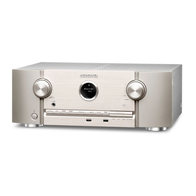
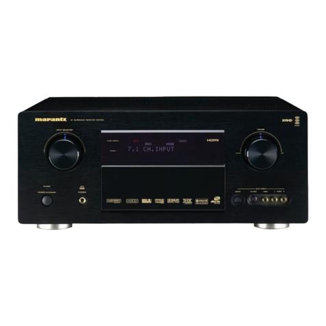
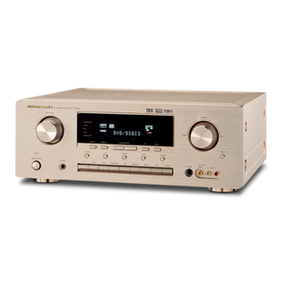
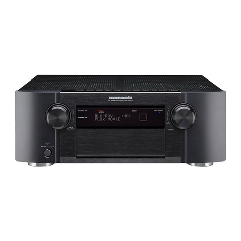
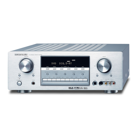
Marantz SR-63 User manual

ERR
en
Bean
BRE
ZZ.’
Model
SR-63
User
Guide
a
cae
Audio
/
Video
Stereo
Receiver

WARRANTY
For
warranty
information,
contace
your
local
Marantz
distributor.
RETAIN
YOUR
PURCHASE
RECEIPT
Your
purchase
receipt
is
your
permanent
record
of
a
valuable
purchase.
It
should
be
kept
in
a
safe
place
to
be
referred
to
as
neccessary
for
insurance
purposes
or
when
corresponding
with
Marantz.
IMPORTANT
When
seeking
warranty
service,
it
is
the
responsibility
of
the
consumer
to
establish
proof
and
date
of
purchase.
Your
purchase
receipt
or
invoice
is
adequate
for
such
proof.
FOR
U.K.
ONLY
This
undertaking
is
in
addition
to
a
consumer's
statutory
rights
and
does
not
affect
those
rights
in
any
way.
GARANTIE
Pour
des
informations
sur
fa
garantie,
contacter
le
distributeur
local
Marantz.
CONSERVER
L'ATTESTATION
D'ACHAT
L'attestation
d'achat
est
la
preuve
permanente
d'un
achat
de
valeur.
La
conserver
en
lieu
sur
pour
s'y
reporter
aux
fins
d'obtention
d’une
couverture
d'assurance
ou
dans
le
cadre
de
correspondances
avec
Marantz.
IMPORTANT
Pour
l'obtention
d'un
service
couvert
par
la
garantie,
il
incombe
au
client
d'établir
fa
preuve
de
|'achat
et
d'en
corroborer
la
date.
Le
regu
ou
la
facture
constituent
des
preuves
suffisantes.
GARANTIE
Bei
Garantiefragen
wenden
Sie
sich
bitte
an
Ihren
Marantz-Handler.
HEBEN
SIE
IHRE
QUITTING
GUT
AUF
Die
Quittung
dient
Ihnen
als
bleibende
Unterlage
flr
Ihren
wertvollen
Einkauf
Das
Aufbewahren
der
Quittung
ist
wichtig,
da
die
darin
enthaltenen
Angaben
fir
Versicherungswecke
oder
bei
Korrespondenz
mit
Marantz
angeftihrt
werden
mussen.
WICHTIG!
Bei
Garantiefragen
muB
der
Kunde
eine
Kaufunterlage
mit
Kaufdatum
vorlegen.
Ihren
Quittung
oder
Rechnung
ist
ais
Unterlage
ausreichend.
NEDERLANDS
GARANTIE
Voor
inlichtingen
omtrent
garantie
dient
u
zich
tot
uw
plaatselijke
Marantz.
UW
KWITANTIE,
KASSABON
E.D.
BEWAREN
Uw
kwitantie,
kassabon
e.d.
vormen
uw
bewijs
van
aankoop
van
een
waardevol
artikel
en
dienen
op
een
veilige
plaats
bewaard
te
worden
voor
evt,
verwijzing
bijy,
in
verbend
met
verzekering
of
bij
correspondentie
met
Marantz.
BELANGRIJK
Bij
een
evt,
beroep
op de
garantie
is
het
de
verantwoordelijkheid
van
de
consument
een
gedateerd
bewijs
van
aankoop
te
tonen.
Uw
kassabon
of
factuurzijn
voldoende
bewijs.
GARANTIA
Para
obtener
informacién
acerca
de
la
garantia
pongase
en
contacto
con
su
distribuidor
Maraniz.
GUARDE
SU
RECIBO
DE
COMPRA
Su
recibo
de
compra
es
su
prueba
permanente
de
haber
adquirido
un
aparato
de
valor,
Este
recibo
deberé
guardarlo
en un
lugar
seguro
y
utilizarlo
como
referencia
cuando
tenga
que
hacer
uso
del
seguro
o
se
ponga
en
contacto
con
Marantz.
IMPORTANTE
Cuando
solicite
el
servicio
otorgado
por
la
garantia
el
usuario
tiene
la
responsabilidad
de
demonstrar
cudndo
efectué
la
compra.
En
este
caso,
su
recibo
de
compra
sera
la
prueba
apropiada.
Condizioni
di
garanzia
L'apparecchio
e'
garantito
per
365
giorni
dalta
data
di
acquisto
comprovata
da
un
documento
attestante
il
nominativo
de!
rivenditore
e
la
data
di
vendita.
La
garanzia
sara’
prestata
con
la
sostituzione
o
riparazione
gratuita
delle
parti
difettose.
Non
sono
coperti
da
garanzia
difetti
derivanti
da
uso
improprio,
errata
installazione,
manutenzione
effettuata
da
personale
non
autorizzato
0,
comunque,
da
circostanze
che
non
possano
riferirsi
a
difetti
di
tunzionamento
dell'apparecchio.
Sono
inoltre
esclusi
dalla
garanzia
gli
interventi
inerenti
l'installazione
e
l'allacciamento
agli
impianti
di
alimentazione.
Gli
apparecchi
verranno
riparati
presso
i
nostri
Centri
di
Assistenza.
Le
spese
ed
i
rischi
di
trasporto
sono
a
carico
del
cliente.
La
casa
costruttrice
declina
ogni
responsabilita’
per
danni
diretti
o
indiretti
provocati
dalla
inosservanza
delle
prescrizioni
di
installazione,
uso
e
manutenzione
dettagliate
nel
presente
manuaie.
Per
informazioni
sull'abbonamento
al
Servizio
Assistenza
postgaranzia
e
per
conoscere
l'indirizzo
dei
Centri
Assistenza
Marantz
rivolgetevi
al
nostro
servizio
consumatori
(telefono
1678-20026
-
numero
verde).
PORTUGUES
GARANTIA
Para
informagdes
sobre
a
garantia,
contactar
o
distribuidor
Marantz
local.
GUARDAR
O
RECIBO
DE
COMPRA
O
recibo
€
0
registo
permanente
da
compra
que
fez.
Deve
ser
guardado
num
local
seguro,
para
ser
apresentado
em
questées
relacionadas
com
O
seguro
OU
para
quando
tiver
de
contactar
a
Marantz.
IMPORTANTE
Quando
procurar
assisténcia
técnica
ao
abrigo
da
garantia,
é da
responsabilidade
do
consumidor
estabelecer
a
prova
e
daa
de
compra.
O
recibe
é
prova
adequada.
SVENSKA
GARANTI
F6r
information
om
garantin,
kontakta
Marantz
lokalagent.
SPAR
KVITTOT
Kvittot
ar
ett
inképsbevis
pA
en
vardefull
vara.
Det
skall
forvaras
sakert
och
hanvisas
till
vid
férsakringsfall
eller
vidkorrespondens
mod
Marantz.
VIKTIGT
F6
att
garantin
skall
galla
ar
det
kundens
sak
att
framstalla
bevis
och
datum
om
k6pet.
Kvitto
eller
faktura
r
tillraokligt
bevis
f6
detta.

CONTENTS
LIST
EA
GUSH
so
vise
cveetinvessiidh
cesgeeethsecsssscscupcetvorusctesatdcesnctca
stececctebecsescsauestsscsscnsconsdbatvepsloneotogsSeisovesierasedet
cvegesteantensddsedivedeceaeeegedtvecnsenspbaieesede
page
2
FRANCAIS
5
ssseteescescctesthiscuceuaascandeceitanescacs
cu
teetssovsnedocoutcesavetWaseatacnacs
doateutedassassesassesnessentewutsdsedadgsdstveneostateegstuseatbaas
genseveveresaaeseeesesazeestnse
page
10
DQ
UIES
OEY
cocoa
scacccs
erese
haces
BES
ses
cuss
Reese
eae
ae
eb
Ti
tca
su
en
saEa
rb
an
cece
watts
Sa
cua
ft
ru
soutien
ds
dassiund
dew
cannewundczee
sbeaaveseuenengeeeuseduate
seach
svaeeuceurdepeand
Seite
19
Nederlands
Seccasbubdpsncsnabecncoebuecaebuchevecsaseicheyuaseeestecse
cusUibb
cats
cucescdse
tusuucyatlltesfelotdin
Ril
avi
NTN
eerie
eatin
saves
hevecbaded
tie
edeasasaee
pagina
28
EGDEPON
ss
-scsssocotsecococnssax
sesnncovdabsctasivesuersonseba
cod0eh
Govuasduevegebldeetesebepevevcditnccsnceastvucdesedlatbe¥scuestatgecvoseassesusdiveedeonassesgacususennsddcbegioesedestsgs
pagina
36
Mtl
ri
222
eo
ri
seede
Bivicdehes
cede
cebcedecaseavieeeces
ovtck
vicesvceth
Uateeeactavsces
sues
ibeata
doses
Sissuiouos
leh
useuvevadetaduentavbade
razsegcccuaseace
Galecetsvecseuin
Soviegeatiaanav
pagina
44
POMUGUES
5
cisSivczscncsecestectesde
accel
eb
Sib
cused
egiecd
ti
ed
betecaaaapeka
sai
adbualitcnh
cGeacdveteceptwedhdeetebledscstastesddatoedetodanaSlsonvaisshesssasdetons
svaanedeeeseateced
pagina
52
SVGMSK
eb
vies
iacelvssedsvdiace
sta
eceese
caseaubives
iesudecuns
covsses
cata
tecture
cseuh
Asal
cata
haweaghetesbaubabensaathcrastshesstbesbbeascnenechitavazers
sacdsdetaageaoededuevegneag
sizes
sidan
60
SPOCificeatl
Oris:
5.2
sche
seis
cocci
sae
ssax
G5
Ss8
2a
BSG
SENG
Seed
ee
tee
svat
cick
cece
sha
teehee
weed
eeynne
dasebat
seb
caudeacedpasasecegethatanesestae
does
page
68
FIQUIOS:
iasceicsseetistceideceeesedeseeceeeaveesiceutscsel
covnssevecotncncadescstasvecedutaceataivaaunsnegesaeoensoeinacnsGeasedues
iseddiedsddecesadedbtelnsrstedendyeiieacerseleasetsaveribo
anaes
page
69
ENGLISH:
This
unit
meets
the
requirements
of
EEC
Recommendation
82/499.
FRANCAIS:
Cet
appareil
ext
conforme
aux
directives
82/499
de
la
CEE.
DEUTSCH:
Dises
Gerat
entspricht
der
EWG-Empfehlung
82/499.
NEDERLANDS:
Dit
apparaat
voldoet
aan
de
eisen
van
Aanbeveling
EEG
82/499.
ESPANOL:
Este
aparato
cumple
los
requisitos
establecidos
en
la
directiva
82/499
de
la
CEE.
ITALIANO:
Questo
apparecchio
é
conforme
ai
requisiti
della
direttiva
CEE
82/499.
PORTUGUES:
_
Esta
unidade
foi
concebida
e
manufacturada
em
conformidade
com
a
Recomendagao
82/499
de
Comunidade
Econdémica
Europeia.
SVENSKA:
Denna
apparat
éverenstammer
med
bestammelsema
i
EEC
82/499.
“Este
aparato
!leva
elementos
antiparasitarios
necesarios
para
cumplir
con
los
limites
que
se
estableren
en
el
Anexo
V
del
Reglamento
sobre
Pertubaciones
Radioelectricas
e
Interferencias
aprobado
en
el
Real
Decreto
138/1989.
(B.O.E
de
9
de
Febrero
1989).”.

CONTENTS
LIST
Page
FOREWORD
i
e5is620
Ares
iv
sescuseceuse
deaties
nasties
tuaeeu
bel
onte
pitied
Dyed
aids
LUCA
aty
uence
PES
Ae
cetcodvoceh
dear
oavedadeehaat
a
ich
aa
aed
3
WAEMINGS
<stevsiseses
ate
cts
sents
cadceptoys
Svauiedteens
Slee
le
seeinceteneatvevhddecagtunecegig
dees
vdvea
cosas
anceodan’
s
tunteseapiaeibosetpaadoiasingstteiactuenstaeiaeee
3
Equipment
Mains
Working
Setting
....................ccccccsssccceeceseuesesececeeceseueesecneccueusecesaessusaueceuauseuauaetsnsessesssscaesstssenesassaes
3
IMPOLTAN
feces
sede tiva ster
Pusat
ines
noveran
teens
eeecedeaarse
eters
oad
Sibi
ee
eed
vaca
een
cones
Sue
dedz
cat
ouua
toes
oe
tes
cas
deced
Cevstess
ces
desea
eae
3
How
to
connect
a
plug:
oii2ci.sesesccicevege
secede:
cdecavi
cases
ce
ccusneceivensito
od
ddoie
sab
suces
sua
dhcuadhavasvectadenaledasxedavveucvasesso
sicasasevsduvavnsvedeess
3
Copyright
..
Mette
vn
ucdiunpree
dies
TeNtUN
bane
es
cove
aphveseesveeneeSdansunagaccudaa
ets
tvewalegatapaska
wu
casoeheWucdelsteecsvatveeddetaventae,
dauclethestise
gee
About
This
see
Guide
|
oh
Seg
seats
acSaudedapesuseacaGasuteus
Let
igteatinte
ce
Go
eke
ie
bauanestatoaveptecaeek
nid
ge
Mie
de
waists
based
Sa
siti
Motes
3
PRECAUTIONS
=
isis
cde
toiicde
foc
cbhicgs
clues
Seda
d
lev
ede sch
lesen
ca
nauba
ssundgwiscve
ob’
dovashvnuade
conus
cudinsats
pad
eeeoea
vaguastveuvevesslohuciaesiedbvicinedsioas
3
General
Precautions
653
i0i5).55s55
ectedels
oes
Aah
esedls
eae
Boae
ovsed
ub
geaea
saya
yah
sede
e
obo
aan
foe
deae
Oa
Sea
ks
aubada
daceaevdions
Hovadbinneepueeeeeed
3
CONNECTIONS.
oun...
ccceccceccseecceecaeeeeeereaeeee
saa
gessaialeedax
evs
sovk
gubnu
ed
stevessatteaccavaal
ves
leecusaehseveeeeduckdabenccoecencsbeaueet
severe
itbicseersecsesteees
3
Audlo
System:
ConnectlOnss:
:.:ici2
icccsseveesseseted
os
vecda
ok
bicecs
seed
c
sve
Shee
ee
et
oUbs
cides
casa
wade
boudaes
19
SubUasaintainag
cb
advaannvanootn
Sotaegsdaoenns
3
Antenna:
connectlons
isccsscs
reeseed
ec
eceds
leePave
Sac
esh
cae
vos
du
sauce
ude
tatwuedavasvagans
oobi
cencdaveos
goed
ese
cues
sddehetadecnaceaddeadiaisouceasdelsvangousil
3
Connection
of
turntable
..................
cc
ccecccseccsceueescccccesceeessevecsecussecscsasceucecaeseneseeecescusceaceeaesuesnuessenenes
dvasduthucenieesevcdteasets
3
Connection
of
compact
disc
player
.................cccccccccsseceeeeeseeeeeeeeecceseceusecccuuuuuessseeessuuseseeeeuevssensseecssrsesssssesstssstscstssseese
O
Connection
of
tape
deGk:..:.scissiscivtreiccee
sever
secs
daSesvucencoadec
agate
sSaus
sabe
cawoeeseresedecetonal
Sodiaeaaavenioed
nasties
“S
atiiteewies
roetbcatiesies
3
Connection
of
speaker
Systems
.............
eee
ce
ec
ce
cence
ccsseceeeeeceeseeseseeeeeaueeetssaegeeseeeeaatsuvececcussussasacseseeeisestsesesseesesissnsae
O
Video’system:
connections:
32:2
s.csc.s2:
dada.
5
cc
oSecavedescduces
les
enekede
Sevaden
itis
dadedin
dundee
soekcesededded
weibeeietestiieinss
urine
Connection
Of
TV:
Tuniett:
sie...
fssiccccteseisevaicacedeak
bath
ppotinctnd
voxel
oaesievwea
ceeaaececaseneeiec
sue
oadvdecaaiauencbeteavtasustevececsscoectel
tucuascees
4
Connection
of
CDV
player
i.
::0s.ccs.cceevevetenasn
cavececgedecsutdaced
suwdasccdsdsuedaswavsvancdeavoniidioasanasuuusscecssvestanpbeuseasstbasadstacarcieclietes
4
Connectlon:of
MONITOR
TV:
icsisehSecccsccici
cc
ccackecianens
siceacdegshsandeuedgiel
ys
dsedd
i
Madiaaideee
watdelad
seb
eaaisiaieestoe
deetiestiaelstereerns
4
Connection:
Of
VOR
isieces
cde
heds
See
Ease
dcan
ca
sag
nt
seashadehaaindeabescessutdeesd
Sieaausessupeodabene
eaten
igniestesee
aa
eae
haeeoesteth
4
CONTROLS
AND
THEIR
FUNCTIONS
uuu...
cecccsecccsscseeeeeeceeeeeeeeeecceseesceecegenessuveeusssenscaecceesessreeseeeeeesusitassdicsssseecseessceses
4
OPERATION
000.0...
cccccccssseseceeeseneesensunees
Detbethea
atin
edeetstfeietventeccen
catarsecdtoubsfied
Wevestdseseicec
ohlivigdis
wee
auama
mundi
dean
6
Preparatlon:
:::cc2icc)
cisacesysedaasdiencecds
cctv
bvacacccusatieustitoveeatevandeevedetassaansans
andleutiegneshtsund
davan’nsiydiltecterl
aba
svadecsucaguadrvisetaanents
6
To
listen.to:the:
radlo:
.:::sen
kee
i
AISA
aie
eiv
cc
cadocanaaatesieszagddouaasunataacdauetsrasaweudaepousvantiicuia
deus
Loty
diveetteigubeveisientt
6
Playing
another
AUDIO/VIDEO
program
|
............cccccccccccceecceceeeccuseseeebecccesececuecessuucesecuuscecuursvisesaaeaasaesssuseseseasarestsonsens
6
Use
with
a
tape
recorder
..............0.0..
ddetioagyativichveceana’
sTanetesess
pudvanivequseeke
ui
diebetticied
ebantit
Sacesevecoate
tigated
as
ciatedaneesans
sanevenets
7
Recording
AUDIO/VIDEO
programs
ee te
este
teeta
ceeaeeneenecseeseseeesecsecseesersesseeseeaseceesoesscnesseeasaresscateaaesssesssuusesecnsecsuensansen
7
Wake
up
timer
.............0.0:cccccccccelecseececesesrsesseceees
Sei
oak
dunanabetsteceess
aces
Canaanite
Nottie
vhvadhashiuateited
Ricavo
atiteietiork
7
REMOTE:
CONTROL
UNIT
eccccccucedscecie
Sods
Fecseei
tea
en
eee
cha
segica
ibis
ih
bacavitoed
saeqvus
aaa
ed
dca
ved
uated
dow
biatsseveele«cduxsnisaensecsn
uaa
8
Replacing
the
battenles:
vi.siii.sspecs
ce
Scteces
aces
sense
ed
ivan
os
Seb
seeeeaOleeea
ede
vase
nade
cvewaldetede
sage
ia
ded
cacdedveaedinuaeke@ed
andegndenmeaten
8
CARE
AND
MAINTENANCE
iciicssestusssciiusessicauscce
ce
sucayes
vials
vig
se
ana
oseadey
xia
uadeanigoaediaads
dideliadea
faved
veddsva
Mead
uate
Cleaning
of
equipment
external
Surfaces
oo...
ccc
ceescecccccccceeecescneeeceecessucusuucusensececceesauceeaaa
ea
vesssuanauaenatseensaceniees
9
Fuse
‘replacement:
3.25:
22sch2e.
ste
teides
lis
biaa
cca
edecat
cess
bacacSogecd
iadecha
iia
heced’
bus sat
vadeinde
Sotuody
cuca
dewtatadaadesiueunduse
dadeusltdeacaeoes
9
PRO
Pairs
cco
esac
oesen
Beaten
cee
teak
tac
edsiut
sntaaNs
Jae
Sect
awentaalcetcee
|
oa
covatuvelacaettaaa
tas
site
taanenohis
at
nccdaa
(Dee
nen
ee
steiiupe
setae
dwanec
9
TROUBLESHOOTING
«cai
ini
Serie
ona.
eee
fachiaeete
Rats
Rigen
ane
vagcetliees
fuse
cieteae
iacealthanenee
ions,
9
Does
sound
come
from
only
one
side?
ow...
cee
ee
eceeeeeeeeeeees
a
as
sauaieueinee
this
be
Daggiie
as
Su
manden
cath
gest
aduvdadtvactiok
9
Does
the
receiver
hum,
buzz
or
howl
during
recording
or
playback?
................00.ccccccccccccssscssssssseascceneesesssssersneetersneeesees
D
You
cannot
hear
anything,
and
no
indicator
lights
UP.
....................cccceccesessssscccecceccececesecsesnerevarsedscessvstsassssenseecarseesaans
9
You
cannot
hear
anything,
but
an
indicator
lights
Up.
..............0000:ccccccccscscssscessescecccecescsennecassnsesenecevsesassasacsesseetecaescens
9
Was
the
recording
UNSUCCESSFUL?
«oo...
ccscceecccecessseeeessseeesesseeccsesesssseeccsscessesuecessesseeassurapansaneascacsseesesesesenserensienees
9
Remote
control
unit
is
not
Working,
................::ccccccsscscsssscsccceccecccesssessaeucaeceeceescecescaueusasaaaaucassusegassevssesevaveesscsaessasseasseens
9

FOREWORD
This
section
must
be
read
before
any
connection
is
made
to
the
mains
supply.
WARNINGS
Do
not
expose
the
equipment
to
rain
or
moisture.
Do
not
remove
the
cover
from
the
equipment.
Do
not
push
anything
inside
the
equipment
through
the
ventilation
holes.
Do
not
handle
the
mains
lead
with
wet
hands.
EQUIPMENT
MAINS
WORKING
SETTING
Your
Marantz
product
complies
with
the
household
power
and
safety
requirements
in
your
area.
*/02"
Version
product
can
be
powered
by
230
V
AC.
"/05"
or
"/07"
Version
product
can
be
powered
by
240
V
AC
only.
This
is
a
voltage
selector
(2-position
or
4-position)
on
the
rear
panel
of
the
"/01"
Version
product.
Be
sure
to
set
the
voltage
selector
to
the
mains
voltage
of
your
area
before
using
the
unit.
IMPORTANT:
This
apparatus
is
fitted
with
an
approved
moulded
13
Amp
plug.
To
change
a
fuse
in
this
type
of
plug
proceed
as
follows:
1.
Remove
fuse
cover
and
fuse.
2.
Fix
new
fuse
which
should
be
a
BS1362
5A,
A.S.T.A.
or
BSI
approved
type.
3.
Refit
the
fuse
cover.
lf
the
fitted
plug
is
not
suitable
for
your
socket
outlets,
it
should
be
cut
off
and
an
appropriate
plug
fitted
in
its
place.
If
the
mains
plug
contains
a
fuse,
this
should
have
a
value
of
5A.
If
a
plug
without
a
fuse
is
used,
the
fuse
at
the
distribution
board
should
not
be
greater
than
5A.
NOTE:
The
severed
plug
must
be
destroyed
to
avoid
a
possible
shock
hazard
should
it
be
inserted
into
a
13A
socket
elsewhere.
HOW
TO
CONNECT
A
PLUG
The
wires
in
the
mains
lead
are
coloured
in
accordance
with
the
following
code:
BLUE—"NEUTRAL’
("N")
BROWN—"LIVE’
('L")
1.
The
BLUE
wire
must
be
connected
to
the
terminal
which
is
marked
with
the
letter
"N"
or
coloured
BLACK.
2.
The
BROWN
wire
must
be
connected
to
the
terminal
which
is
marked
with
the
letter
"L"
or
coloured
RED.
3.
Do
not
connect
either
wires
to
the
earth
terminal
in
the
plug
which
is
marked
by
the
letter
"E"
or
by
the
safety
earth
symbol!
~&
or
coloured
green
or
green-and-yellow.
Before
replacing
the
plug
cover,
make
certain
that
the
cord
grip
is
clamped
over
the
sheath
of
the
lead
—
not
simply
over
the
two
wires,
COPYRIGHT
Recording
and
playback
of
any
material
may
require
consent.
For
further
information
refer
to
the
following:
—
Copyright
Act
1956
—
Dramatic
and
Musical
Performers
Act
1958
+
Performers
Protection
Acts
1963
and
1972
—
any
subsequent
statutory
enactments
and
orders.
ABOUT
THIS
USER
GUIDE
Refer
to
the
diagrams
on
page
69
at
the
rear
of
this
user
guide.
The
numbers
on
the
diagrams
correspond
to
those
in
the
text.
All
references
to
the
connections
and
controls
that
are
printed
in
BOLD
type
are
as
they
appear
on
the
unit.
PRECAUTIONS
The
following
precautions
should
be
taken
when
operating
the
equipment.
GENERAL
PRECAUTIONS
When
installing
the
equipment
ensure
that:
—
the
ventilation
holes
are
not
covered;
—
air
is
allowed
to
circulate
freely
around
the
equipment;
—
itis
on
a
vibration-free
surface;
—
it
will
not
be
exposed
to
interference
from
an
external
source;
—
it
will
not
be
exposed
to
excessive
heat,
cold,
moisture
or
dust;
;
—
it
will
not
be
exposed
to
direct
sunlight;
—
it
will
not
be
exposed
to
electrostatic
discharges.
e
Never
place
heavy
objects
on
the
equipment.
e
If
a
foreign
body
or
water
does
enter
the
equipment,
contact
your
nearest
dealer
or
service
center.
e
Do
not
pull
out
the
plug
by
pulling
on
the
mains
lead,
hold
the
plug.
e
It
is
advisable
when
leaving
the
house,
or
during
a
thunderstorm,
to
disconnect
the
equipment
from
the
mains
supply.
CONNECTIONS
AUDIO
SYSTEM
CONNECTIONS
(Figure
1)
ANTENNA
CONNECTIONS
Both
FM
and
AM
antennas
can
be
connected
to
the
receiver
terminals.
The
FM
ANTENNA
terminal
is
used
to
connect
an
FM
antenna
to
the
receiver.
The
MW/LW
terminal
and
the
GND
terminal
are
used
to
connect
the
high-performance,
low-
impedance,
AM
loop
antenna
that
is
provided
with
the
receiver.
The
AM
loop
antenna
can
be
used
on
top
of
the
receiver
or
can
be
mounted
on
a
suitable
rack
or
shelf
near
the
receiver.
Interference
may
be
reduced
if
the
receiver
is
earthed.
CONNECTION
OF
TURNTABLE
Connect
the
L
(Left)
output
lead
of
the
turntable
to
the
“L'
PHONO
jack
of
this
unit,
and
connect
the
R
(Right)
output
lead
to
the
“R"
PHONO
jack.
Also
be
sure
to
connect
the
turntable’s
earthing
wire
to
the
GND
jack
of
this
unit.
The
GND
jack
does
not
have
to
be
connected
if
the
turntable
is
not
provided
with
an
earthing
wire.
CONNECTION
OF
COMPACT
DISC
PLAYER
Connect
the
output
jacks
of
your
CD
player
to
the
CD
jacks
of
this
unit.
CONNECTION
OF
TAPE
DECK
Connect
the
IN
(recording
input)
jacks
of
the
tape
deck
to
the
TAPE
OUT
jacks
of
this
unit,
and
connect
the
OUT
(playback
output)
jacks
of
the
tape
deck
to
the
TAPE
IN
jacks
of
this
unit.
CONNECTION
OF
SPEAKER
SYSTEMS
(Figure
2)
This
unit
is
equipped
with
two
sets
of
SPEAKER
SYSTEM
terminals
-
SYSTEM
1
terminals
and
SYSTEM
2
terminals.
The
speaker
system
is
usually
connected
to
the
SYSTEM
1
terminals.
e
The
speakers
in
the
speaker
system
should
have
an
impedance
of
between
8
and
16
ohms.
If
speakers
with
an
impedance
of
less
than
8
ohms
are
connected,
the
protection
circuitry
may
be
activated
during
play.
e
Connect
the
Right
channel
speaker
to
the
R
terminals,
and
the
Left
channel
speaker
to
the
L
terminals.

e
The
output
terminals
have
positive
(+:
Red)
and
negative
(—:
Black)
polarity,
and
each
speaker
aiso
has
the
same
polarity
(+
and
—).
When
connecting
the
speakers,
be
sure
to
connect
the
terminals
with
the
same
polarity
(+
with
+,
—
with
NOTE:
If
two
speaker
systems
are
to
be
connected
to
the
unit,
each
of
the
speakers
should
have
an
impedance
of
16
ohms
or
more.
/f
speakers
with
an
impedance
of
less
than
16
ohms
are
connected,
the
protection
circuit
may
be
activated
during
play,
making
normal
stereo
playback
impossible.
VIDEO
SYSTEM
CONNECTIONS
(Figure
3)
CONNECTION
OF
TV
TUNER
Connect
the
AUDIO
OUT
L
(Left)
jack
to
the
TV
IN
L
jack,
and
connect
the
AUDIO
OUT
R
(Right)
jack
to
the
TV
IN
R
jack.
Connect
the
VIDEO
OUT
jack
to
the
TV
IN
jack.
CONNECTION
OF
CDV
PLAYER
Connect
the
AUDIO
OUT
L
(Left)
jack
to
the
CDV
IN
L
jack,
and
connect
the
AUDIO
OUT
R
(Right)
jack
to
the
CDV
IN
R
jack.
Connect
the
VIDEO
OUT
jack
to
the
CDV
IN
jack.
CONNECTION
OF
MONITOR
TV
Connect
the
VIDEO
IN
jack
to
the
TV
MONI.OUT
jack.
CONNECTION
OF
VCR
Connect
the
AUDIO
OUT
L
(Left)
jack
to
the
VCR
IN
L
jack,
and
connect
the
AUDIO
OUT
R
(Right)
jack
to
the
VCR
IN
R
jack.
Connect
the
AUDIO
IN
L
(Left)
jack
to
the
VCR
OUT
L
jack,
and
connect
the
AUDIO
IN
R
(Right)
jack
to
the
VCR
OUT
R
jack.
Connect
the
VIDEO
OUT
jack
to
the
VCR
IN
jack,
and
connect
the
VIDEO
OUT
jack
to
the
VCR
OUT
jack.
CONTROLS
AND
THEIR
FUNCTIONS
(Figure
4)
@)
TERMINAL
FOR
AN
FM
ANTENNA,
75
OHMS
For
connecting
an
external
FM
antenna
with
a
circular
plug,
or
for
connecting
a
cable
network.
@
TERMINALS
FOR
AN
AM
ANTENNA
AND
EARTH
For
connecting
the
AM
loop
antenna
supplied.
Use
the
terminals
marked
MW/LW
and
GND.
In
areas
where
the
AM
loop
antenna
supplied
gives
unsatisfactory
results,
it
is
recommended
that
the
receiver
be
connected
to
an
outdoor
antenna.
Use
the
terminal
marked
AM
for
this.
An
earthing
lead
can
be
connected
to
the
terminal
marked
GND
to
further
reduce
interference.
(3)
GND
(GROUND)
terminal
For
connecting
an
earthing
wire
of
a
record
player
to
prevent
hum.
(4)
PHONO
JACKS
For
connecting
a
record
player
with
an
MM
(Moving
Magnet)
cartridge.
(©)
ep
sacks
For
connecting
a
Compact
Disc
player.
©
TAPE
JACKS
The
TAPE
QUT
jacks
are
for
connecting
the
line
inputs
(LINE
IN)
of
a
tape
recorder.
The
TAPE
IN
jacks
are
for
connecting
the
line
outputs
(LINE
OUT)
of
a
tape
recorder.
@)
TV
AUDIO
JACKS
The
TV
jacks
are
for
connecting
the
audio
line
outputs
(AUDIO
OUT)
of
a
TV
tuner.
LD/CDV
AUDIO
JACKS
The
LD/CDV
AUDIO
jacks
are
for
connecting
the
audio
line
outputs
(AUDIO
OUT)
of
an
LD/CDV
player.
(@)
VCR
AUDIO
JACKS
The
VCR
AUDIO
OUT
jacks
are
for
connecting
the
audio
line
input
(AUDIO
IN)
of
a
video
cassette
recorder.
The
VCR
AUDIO
IN
jacks
are
for
connecting
the
audio
line
output
(AUDIO
OUT)
of
a
video
cassette
recorder.
REMOTE
CONTROL
JACKS
The
IN
jack
is
for
connecting
an
extra
remote
control
receiver.
The
OUT
jack
is
for
conveying
the
remote
control
signals
to
other
remote-controllable
equipment.
@)
TV
VIDEO
IN
JACK
The
TV
VIDEO
IN
jack
is
for
connecting
the
video
output
(VIDEO
OUT)
of
a
TV
tuner.
q
LD/CDV
VIDEO
IN
JACKS
The
LD/CDV
VIDEO
IN
jack
if
for
connecting
the
video
output
(VIDEO
OUT)
of
an
LD/CDV
player.
@
VCR
VIDEO
IN/OUT
JACKS
The
VCR
VIDEO
OUT
jack
is
for
connecting
the
video
input
(VIDEO
IN)
of
a
video
cassette
recorder.
The
VCR
VIDEO
IN
jack
is
for
connecting
the
video
output
(VIDEO
OUT)
of
a
video
cassette
recorder.
TV
MONI.
JACK
For
connecting
a
monitor
TV
or
a
TV
set
with
a
video
input
jack
®
SCAN-STEP
SELECTOR
(SR-63/01
only)
Changes
the
step
when
the
tuner
searches
for
the
next
station
up
or
down
the
scale.
In
Europe
this
switch
should
be
set
to
50
kHz
steps
in
FM
and
9
kHz
steps
in
AM.
When
the
SCAN
STEP
selector
is
set
to
the
position
for
100
kHz/FM
and
10kHz/AM,
the
receiving
band
changes
as
follows.
FM
band:
87.5
MHz
to
108
MHz,
in
100
kHz
steps.
AM
band:
520
kHz
to
1710
kHz,
in
10
KHz
steps.
CAUTION
THE
UNIT
MUST
BE
TURNED
OFF
BEFORE
CHANGING
THE
SCAN
STEP
SELECTOR
SWITCH
POSITION.
FM
DE-EMPHASIS
SWITCH
(SR-63/01
only)
The
SR-63/01
models
are
equipped
with
switchable
de-
emphasis.
The
de-emphasis
switch
works
in
conjunction
with
the
scan-step
selector
switch.
The
de-emphasis
is
set
to
50
ws
when
delivered
from
the
factory.
W)
SPEAKER
SYSTEM
CONNECTIONS
For
connecting
one
or
two
pairs
of
loudspeakers,
see
Figure
2.
See
also
the
"GENERAL
INFORMATION"
section.
AC
OUTLETS
(SWITCHED)
(SR-63/01,02
only)
By
connecting
these
outlets
to
the
power
plugs
of
up
to
two
components
such
as
a
CD
player,
tape
deck
and/or
VCR
set
(the
audio
outputs
of
which
are
connected
to
this
unit)
and
by
leaving
their
power
switches
set
to
ON,
the
components’
power
will
be
switched
ON/OFF
in
conjunction
with
the
POWER
switch
of
this
unit.
The
total
power
consumption
of
the
connected
components
should
not
exceed
50
W
(SR-63/02)
or
100
W
(SR-
63/01).
The
fuse
provided
is
solely
for
the
AC
OUTLETS
(SR-63/02
only).

MAINS
LEAD
For
connecting
to
a
wall
AC
outlet.
@0)
POWER
SWITCH
Press
this
switch
to
turn
the
receiver
on.
Press
it
again
to
turn
the
receiver
off.
@)
SOUND
SELECT
BUTTONS
Use
to
listen
to
the
audio
playback
from
the
record
player,
Compact
Disc
player
or
tape
recorder,
which
is
connected
to
the
corresponding
jacks.
When
the
TAPE
MONITOR
button
is
pressed,
the
TAPE
MONITOR
indicator
lights
up.
@
INFRARED
SENSOR
AND
STANDBY/IR
RECEIVED
INDICATOR
Receives
infrared
signals
from
the
remote
control
unit
supplied.
@
TAPE
MONITOR
INDICATOR
When
the
TAPE
MONITOR
button
is
pressed,
the
TAPE
MONITOR
indicator
lights
up.
@4
SOUND/VISUAL
SELECT
BUTTON
Use
to
listen
to
audio
and/or
video
playback
from
the
TV
tuner,
CD/CDV
player
or
video
cassette
recorder,
which
is
connected
to
the
corresponding
jacks.
@)
DISPLAY
WINDOW
(Figure
4)
(@)
TUNED
INDICATOR
AUTO
INDICATOR
©
PRESET
INDICATOR
(D)
STEREO
INDICATOR
(©
AUTO
MEMO
INDICATOR
©
WAKE
UP
INDICATOR
©
MEMO
INDICATOR
(H)
PROGRAM
SOURCE
INDICATOR
()
FREQUENCY/PRESET
NUMBER
INDICATOR
@6)
TUNER
MODE
BUTTONS
FM/MW/LW
band
selectors
Press
the
FM
button
to
select
the
FM
tuning
band
and
MW/LW
button
to
select
the
MW/LW
tuning
band.
According
to
the
band
selected,
the
FM
or
MW/LW
band
will
be
displayed
in
the
display
window.
MODE
button
When
this
button
is
pressed
in
the
FM
mode
and
the
AUTO
indicator
is
illuminated,
the
receiver
will
indicate
stereo
for
a
stereo
broadcast.
FM
and
AM
band
selectors
Press
the
FM
button
to
select
the
FM
tuning
band
and
AM
button
to
select
the
AM
tuning
band.
According
to
the
bands
selected,
fhe
FM
or
AM
band
will
be
displayed
in
the
display
window.
@
TUNER
CONTROL
BUTTONS
Numeric
buttons
1
-
0
Use
these
buttons
to
specify
the
number
of
a
preset
station.
ONCE
timer
button
Use
this
button
to
set
the
once
timer.
DAILY
timer
button
Use
this
button
to
set
the
once
timer.
MEMO
button
When
this
button
is
pressed,
the
preset
station
memory
(MEMO)
indicator
in
the
display
window
starts
blinking.
Select
the
desired
preset
number
with
the
numeric
buttons
to
store
the
displayed
frequency.
This
button
is
also
used
for
wake-up
timer
operation.
F/P
(frequency/preset)
button
Press
this
button
to
change
the
frequency/preset
number
indication
in
the
display
window.
O/CL
(0/clear)
button
Press
this
button
to
cancel
the
station-memory
setting
mode
or
preset
scan
tuning.
P.SCAN
button
After
pressing
this
button,
press
the
UP
or
DOWN
button
to
scan
the
preset
stations.
The
receivable
preset
stations
are
scanned
in
the
direction
designated
by
the
UP
or
DOWN
button
and
can
be
listened
to
for
about
5
seconds.
WAKE
UP
button
When
this
button
is
pressed,
the
receiver
enters
wake-up
memory
mode.
This
button
is
also
used
to
check
the
programs
stored
in
wake-up
memory.
@8)
TUNING/P.SCAN
BUTTONS
Press
the
UP
TUNING/P.SCAN
button
to
increase
the
tuning
frequency
for
manual
or
auto
tuning.
Press
the
DOWN
TUNING/P.SCAN
button
to
decrease
the
tuning
frequency.
These
buttons
are
also
used
to
scan
the
preset
stations
manually.
Use
to
scan
up/down
the
preset
stations.
lf
these
buttons
are
to
be
used
for
scanning
preset
stations,
first
press
the
P.SCAN
button,
then
press
the
UP
or
DOWN
button.
Press
the
UP
P.SCAN
button
to
scan
the
higher
numbered
preset
stations
for
about
5
seconds
each.
Press
the
DOWN
P.SCAN
button
to
scan
the
lower
numbered
preset
stations
for
about
5
seconds
each.
To
stop
scanning,
press
either
of
the
P.SCAN
buttons.
@9
VOLUME
CONTROL
Use
this
control
to
adjust
the
overall
sound
level.
€)
PHONES
SOCKET
FOR
STEREO
HEADPHONES
Use
to
connect
stereo
headphones
with
an
impedance,of
8
to
1000
ohms.
By
unlocking
the
SPEAKERS
1/2
select
buttons,
it
is
possible
to
listen
only
via
the
headphones.
€}))
SPEAKERS
1/2
SELECT
BUTTONS
Use
to
switch
the
loudspeakers
connected
to
the
SPEAKERS
terminal
on
and
off.
G2)
BASS
EQ.
BUTTON
Press
this
button
to
enhance
the
bass
sound
(+12
dB,
at
60
Hz).
63
BASS
AND
TREBLE
TONE
CONTROLS
The
BASS
control
is
used
to
increase
or
decrease
the
low-
frequency
response.
Rotating
the
control
clockwise
increases
the
low-frequency
response.
Conversely,
rotating
the
control
counterclockwise
decreases
it.
The
TREBLE
control
is
used
to
increase
or
decrease
the
high
frequency
response.
Rotating
the
control
clockwise
increases
the
high-frequency
response.
Rotating
the
control
counter-
clockwise
decreases
it.
@4
BALANCE
CONTROL
Turn
this
control
to
move
the
sound
image
to
the
right
or
left.

OPERATION
PREPARATION
Before
going
through
the
"OPERATION"
section,
set
the
receiver
as
follows:
1.
2.
Ensure
that
the
VOLUME
control
is
set
to
minimum
in
order
to
prevent
damage
to
your
loudspeakers.
Switch
the
receiver
on
with
the
POWER
switch.
PRE-ON
and
READY
are
displayed
in
the
display
window
for
a
while.
.
Switch
the
loudspeakers
on
with
the
SPEAKERS
1/2
select
buttons.
Button
1
pressed
in:
For
loudspeakers
connected
to
the
SYSTEM
1
loudspeaker
connection.
Button
2
pressed
in:
For
loudspeakers
connected
to
the
SYSTEM
2
loudspeaker
connection.
TO
LISTEN
TO
THE
RADIO
AUTO
AND
MANUAL
TUNING
With
manual
tuning,
each
time
either
of
the
TUNING/P.SCAN
buttons
is
pressed,
the
tuning
frequency
changes
by
one
step,
allowing
yol
to
find
stations
manually.
With
auto
tuning,
the
receiver
automatically
scans
the
tuning
band
and
stops
at
a
station
having
a
sufficient
signal
strength.
1.
2.
3.
4.
5.
6.
Select
the
desired
band
with
the
FM
or
MW/LW
button.
"FM"
or
“MW/LW"
appears
in
the
display
window.
For
FM
stereo
reception,
press
the
MODE
button
so
that
the
AUTO
indicator
lights
up.
Press
either
of
the
TUNING/P.SCAN
buttons
to
select
the
desired
station
(manual
tuning).
When
the
TUNING/P.SCAN
button
is
kept
pressed
for
more
than
0.5
second,
the
receiver
starts
to
scan
the
selected
band
and
stops
at
a
station
having
a
sufficient
signal
strength
(auto
tuning).
When
the
TUNING/P.SCAN
button
is
kept
pressed
during
auto
tuning,
the
scanning
speed
increases.
Slowly
adjust
the
VOLUME
control.
Adjust
the
stereo
balance
with
the
BALANCE
control.
Adjust
the
BASS
and
TREBLE
controls
to
your
preference.
PRESET
TUNING
Up
to
a
total
of
30
FM
or
MW/LW
stations
can
be
preset
and
recalled.
Auto
Presetting
This
section
describes
the
auto
presetting
of
FM,
AM
or
MW/LW
stations
under
preset
numbers
1-30
in
this
order.
&-
WD
N=
.
Press
the
FM
button.
.
Press
the
F/P
button
so
that
the
frequency
is
displayed
in
the
display
window.
.
Press
the
TUNING/P.SCAN
buttons
so
that
the
lowest
FM
station
is
received.
.
While
pressing
the
MEMO
button,
press
the
UP
TUNING/P.SCAN
button.
The
AUTO
MEMO
indicator
and
the
MEMO
indicator
start
blinking
and
the
auto
scanning
starts.
.
When
an
FM
station
with
a
sufficient
signa!
strength
is
received,
the
broadcast
is
heard
for
about
5
seconds.
NOTES:
e
During
this
period,
the
setting
of
the
following
buttons
can
be
changed:
MODE
button
FM
or
MW/LW
button
e
|f
the
station
being
received
is
not
the
one
you
want
to
store,
press
the
UP
TUNING/P.SCAN
button
during
this
period
to
resume
auto
scanning.
.
When
the
station
has
been
received
for
about
5
seconds,
the
station
is
automatically
stored
under
the
preset
number
1
(P1).
This
procedure
is
followed
for
all
stations
having
a
sufficient
signal
strength
and
then
stops.
7.
8.
Press
the
MW/LW
button
and
the
TUNING/P.SCAN
button
so
that
the
lowest
MW
station
is
received.
Repeat
steps
4
to
6
for
MW/LW
stations.
NOTES:
e
To
stop
auto
scanning
during
auto
presetting,
press
the
O/CL
button.
e
The
last
preset
station
can
be
replaced
with
the
newly
preset
station.
e
When
one-digit
number
is
entered
while
programming
or
recalling
the
preset
memory,
it
will
be
accepted
within
3
seconds.
If
the
number
is
entered
together
with
“O"
e.g.
“O1",
it
will
be
accepted
immediately.
MANUAL
PRESETTING
1.
2.
3.
4.
Tune
in
the
desired
station
with
manual
or
auto
tuning.
For
FM
stations,
be
sure
to
set
the
MODE
button.
Press
the
MEMO
button.
The
MEMO
indicator
will
flash
for
about
5
seconds.
Select
the
desired
preset
number
under
which
the
displayed
frequency
is
to
be
stored
with
the
numeric
buttons.
Repeat
steps
1
to
3
for
other
preset
numbers.
RECALLING
A
PRESET
STATION
1.
Press
the
F/P
button
so
that
the
preset
station
number
appears
in
the
display
window.
2.
Input
the
preset
number
with
the
numeric
buttons.
3.
Slowly
adjust
the
VOLUME
control.
4.
Adjust
the
stereo
balance
with
the
BALANCE
control.
5.
Adjust
the
BASS
and
TREBLE
controls
to
your
preference.
AUTO
PRESET
SCAN
1.
Press
the
F/P
button
so
that
the
preset
station
number
appears
in
the
display
window.
2.
Press
the
P.SCAN
button.
The
PRESET
SCAN
indicator
will
start
flashing.
3.
While
the
PRESET
SCAN
indicator
is
flashing,
press
the
UP
or
DOWN
TUNING/P.SCAN
button.
The
preset
stations
are
received
for
about
5
seconds
sequentially
in
the
specified
direction.
4.
To
stop
preset
scanning,
press
the
0/CL
button.
5.
Slowly
adjust
the
VOLUME
control.
6.
Adjust
the
stereo
balance
with
the
BALANCE
control.
7.
Adjust
the
BASS
and
TREBLE
controls
to
your
preference.
MANUAL
PRESET
SCAN
1.
Press
the
F/P
button
so
that
the
preset
station
number
appears
in
the
display
window.
2.
Press
either
of
the
TUNING/P.SCAN
buttons
to
manually
scan
the
preset
stations.
3.
Slowly
adjust
the
VOLUME
control.
4.
Adjust
the
stereo
balance
with
the
BALANCE
control.
5.
Adjust
the
BASS
and
TREBLE
controls
to
your
preference.
CAUTION:
If
while
receiving
FM,
with
the
MODE
switch
set
to
AUTO
(AUTO
illuminated),
the
signal
received
is
weak,
the
muting
function
may
cause
no
sound
to
be
issued
from
the
loudspeakers.
In
this
case,
press
the
MODE
switch
so
that
the
AUTO
indicator
goes
out.
The
sound
will
be
heard
in
mono.
PLAYING
ANOTHER
AUDIO/VIDEO
PROGRAM
1.
2.
ak
w
Switch
the
desired
sound
source
on
and
set
it
for
playback.
Select
the
desired
audio
and/or
video
source
with
the
SOUND
select
buttons
or
SOUND/VISUAL
select
buttons
on
the
receiver.
The
selected
program
source
is
indicated
in
the
display
window.
.
Slowly
adjust
the
VOLUME
control.
.
Adjust
the
stereo
balance
with
the
BALANCE
control.
.
Adjust
the
BASS
and
TREBLE
controls
to
your
preference.

USE
WITH
A
TAPE
RECORDER
PLAYBACK
1.
Switch
the
tape
recorder
on
and
set
it
for
playback.
2.
Select
the
tape
source
with
the
TAPE
MONITOR
button
on
the
receiver.
3.
Slowly
adjust
the
VOLUME
control.
4,
Adjust
the
stereo
balance
with
the
BALANCE
control.
5.
Adjust
the
BASS
and
TREBLE
controls
to
your
preference.
RECORDING
AUDIO/VIDEO
PROGRAMS
The
signal
at
OUT
jacks
is
the
same
as
that
which
can
be
heard
through
the
loudspeakers
and/or
headphones.
Make
the
recorder
connected
to
the
jacks
ready
for
recording.
NOTES:
e
Use
of
the
BASS,
TREBLE,
VOLUME
and
BALANCE
controls
will
not
affect
the
recording.
«
If
the
tape
recorder
used
has
separate
heads
for
recording
and
playback,
then
it
is
possible
to
monitor
the
recording.
See
the
recorder
manual.
WAKE
UP
TIMER
When
using
the
wake-up
timer
function
in
combination
with
a
commercially
available
audio
timer,
it
is
possible
to
initiate
a
broadcast
or
playback
of
a
component
connected
to
the
receiver.
TIMER
CONNECTION
Connect
the
mains
power
lead
of
the
receiver
to
the
switched
AC
outlet
of
the
audio
timer.
To
control
Marantz
equipment,
which
is
designed
for
remote
contro!
compatibility
(Data
Bus),
with
the
wake-up
timer
function,
also
connect
the
REMOTE
OUT
terminal.
SETTING
WAKE
UP
TIMER
e
If
you
wish
to
initiate
a
broadcast
at
the
preset
time,
the
appropriate
station
should
be
set
beforehand.
1.
Press
the
WAKE
UP
button.
The
WAKE
UP
indicator
will
start
flashing.
2.
While
the
WAKE
UP
indicator
is
flashing,
press
the
MEMO
button.
The
MEMO
indicator
will
start
flashing
and
the
SEL
indicator
will
light
up.
3.
Select
a
program
source
to
be
played
with
the
SOUND
select
buttons
or
SOUND/VISUAL
select
buttons.
For
a
broadcast,
specify
the
corresponding
preset
station
number
with
the
numeric
buttons.
4.
When
CD,
LD/CDV
or
PHONO
is
selected,
"NUMBER"
appears
in
the
display
window.
Specify
the
desired
selection
number
with
the
numeric
buttons.
e
If
the
first
selection
is
desired,
it
is
not
necessary
to
specify
the
selection
number.
5.
Select
the
timer
method;
once
or
daily.
If
the
once
timer
is
desired,
press
the
1/ONCE
button.
If
the
daily
timer
is
desired,
press
the
2/DAILY
button.
The
WAKE
UP
indicator
lights
up
and
the
setting
of
the
wake-
up
memory
is
completed.
The
presetting
of
the
once
timer
will
t
be
erased
when
the
broadcast
or
playback
is
initiated.
The
presetting
of
the
daily
timer
will
be
maintained,
and
every
day,
at
the
preset
time,
the
timer
will
turn
the
power
on
to
all
of
the
equipment.
6.
To
check
the
program
contents,
press
the
WAKE
UP
button.
The
programmed
preset
station
number
or
selection
number
(CD,
LD/CDV
or
PHONO)
will
be
displayed
and
then
“ONCE"
or
“DAILY”
will
appear
in
the
display
window,
lf
the
programmed
content
is
wrong
or
if
the
program
is
to
be
modified,
re-start
the
procedure
from
the
beginning.
e
lf
the
WAKE
UP
button
is
pressed
again,
the
WAKE
UP
indicator
will
go
out
and
the
receiver.
will
leave
the
timer
setting
mode.
However,
the
memory
will
not
be
erased.
To
recall
the
memory
again,
press
the
WAKE
UP
button.
7.
Set
the
timer
to
the
desired
time.
The
timer
will
turn
all
of
the
equipment
on
at
the
preset
time,
and
initiate
playback
or
broadcast
mode.
Note:
Should
the
tape
recorder
not
start
playback
by
the
wake
up
timer,
set
the
Timer
Play
switch
on
the
tape
recorder
to
ON.

REMOTE
CONTROL
UNIT
(Figure
5)
For
detail
operation
instruction,
please
refer
to
respective
sections
of
receiver.
STANDBY
KEY
Press
this
key
to
turn
off
the
receiver.
NOTE:
If
the
TV,
VCR
1
or
VCR
2
function
has
been
selected,
the
key
shall
be
pressed
for
3
seconds
or
more.
TUNER
CONTROL
KEYS
NUMERIC
KEYS
1-0
Use
these
keys
to
specify
the
number
of
a
preset
station.
TUNING
KEYS
+/-—
Function
as
the
same
as
the
TUNING/P.SCAN
buttons
in
the
receiver.
[3]
MEMO
KEY
(MEMO,
CH/PGM)
Functions
the
same
as
the
MEMO
button
of
the
tape
deck
and
the
F/P
button
of
the
receiver.
[4]
AMS
KEY
The
AMS
button
is
used
to
initiate
Automatic
Music
Search.
For
detail,
please
refer
to
instruction
of
your
cassette
deck
player.
[5]
CASSETTE
DECK
OPERATION
KEYS
<<
KEY
Pressing
this
key
fast-rewinds
the
tape.
>
KEY
Pressing
this
key
starts
playback
or
recording.
p>
KEY
Pressing
this
key
fast-forwards
the
tape.
REC
KEY
Pressing
this
key
engages
the
rec
pause
mode.
To
initiate
recording
from
the
rec
pause
mode,
press
the
»
key
or
Il
(Pause)
key.
Il
(PAUSE)
KEY
Pressing
this
key
during
playback
or
recording
stops
the
tape
deck
without
clearing
the
mode
setting,
and
pressing
it
again
caused
playback
or
recording
to
be
resumed.
<>»
KEY
Pressing
this
key
changes
the
tape
playing
direction.
DECK
B
KEY
(for
double
cassette
deck
only)
When
this
key
is
pressed,
DECK
B
can
be
operated.
wg
(Stop)
KEY
Pressing
this
key
stops
all
tape
transport
functions.
DECK
A
KEY
(for
double
cassette
deck
only)
When
this
key
is
pressed,
DECK
A
can
be
operated.
[6]
SOURCE
SELECTION
KEYS
Pressing
one
of
these
keys
selects
the
program
source.
if
the
SR-63
is
in
the
power
standby
mode,
its
power
is
turned
on
when
a
source
selection
key
is
pressed.
VOLUME
KEYS
Pressing
UP
key
increases
whole
sound
level.
Pressing
DOWN
key
decreases
it.
MUTE
KEY
Pressing
this
key
immediately
decreases
the
sound
level
by
40
dB
and
the
MUTE
display
appears.
To
resume
the
previous
level,
press
this
key
again.
[9]
MODE
KEY
Functions
as
the
same
as
the
MODE
button
in
the
receiver.
REPLACING
THE
BATTERIES
1.
Push
the
tab
on
the
battery
compartment
lid
on
the
rear
of
the
remote
control
unit
and
pull
up
on
the
lid.
(Figure
5)
2.
Place
two
new
"AAA"
size
batteries
into
the
compartment.
Be
sure
to
insert
them
in
the
correct
directions,
as
indicated
by
the
+
and
—
markings
on the
bottom
of
the
compartment.
(Figure
5)
3.
Place
the
battery
compartment
lid
in
the
original
position.
*The
life
of
batteries
used
with
this
unit
is
6
months
to
1
year
(this
varies
depending
on
the
frequency
of
use).
*When
the
batteries
are
nearly
exhausted,
the
operation
range
becomes
shorter.
When
this
happens,
replace
the
batteries
as
soon
as
possible.
“Do
not
use
old
and
new
batteries
together.
Otherwise,
battery
corrosion
could
result.
Table of contents
Other Marantz Stereo Receiver manuals

Marantz
Marantz 2225L User manual

Marantz
Marantz ZR6001 User manual

Marantz
Marantz SR6010 User manual

Marantz
Marantz NR1508 User manual

Marantz
Marantz SR4023 User manual

Marantz
Marantz SR5008 User manual

Marantz
Marantz SR4500 User manual

Marantz
Marantz NR1711 User manual

Marantz
Marantz SR5015 User manual

Marantz
Marantz SR8500 User manual

Marantz
Marantz SR-19EX User manual

Marantz
Marantz SR6200 User manual

Marantz
Marantz 2238 User manual

Marantz
Marantz 4230 User manual

Marantz
Marantz R3001 User manual

Marantz
Marantz SR7300 User manual

Marantz
Marantz SR7012 User manual

Marantz
Marantz SR-5001 User manual

Marantz
Marantz 2240 User manual

Marantz
Marantz SR7013 User manual