FIGURE
NO.
1-1
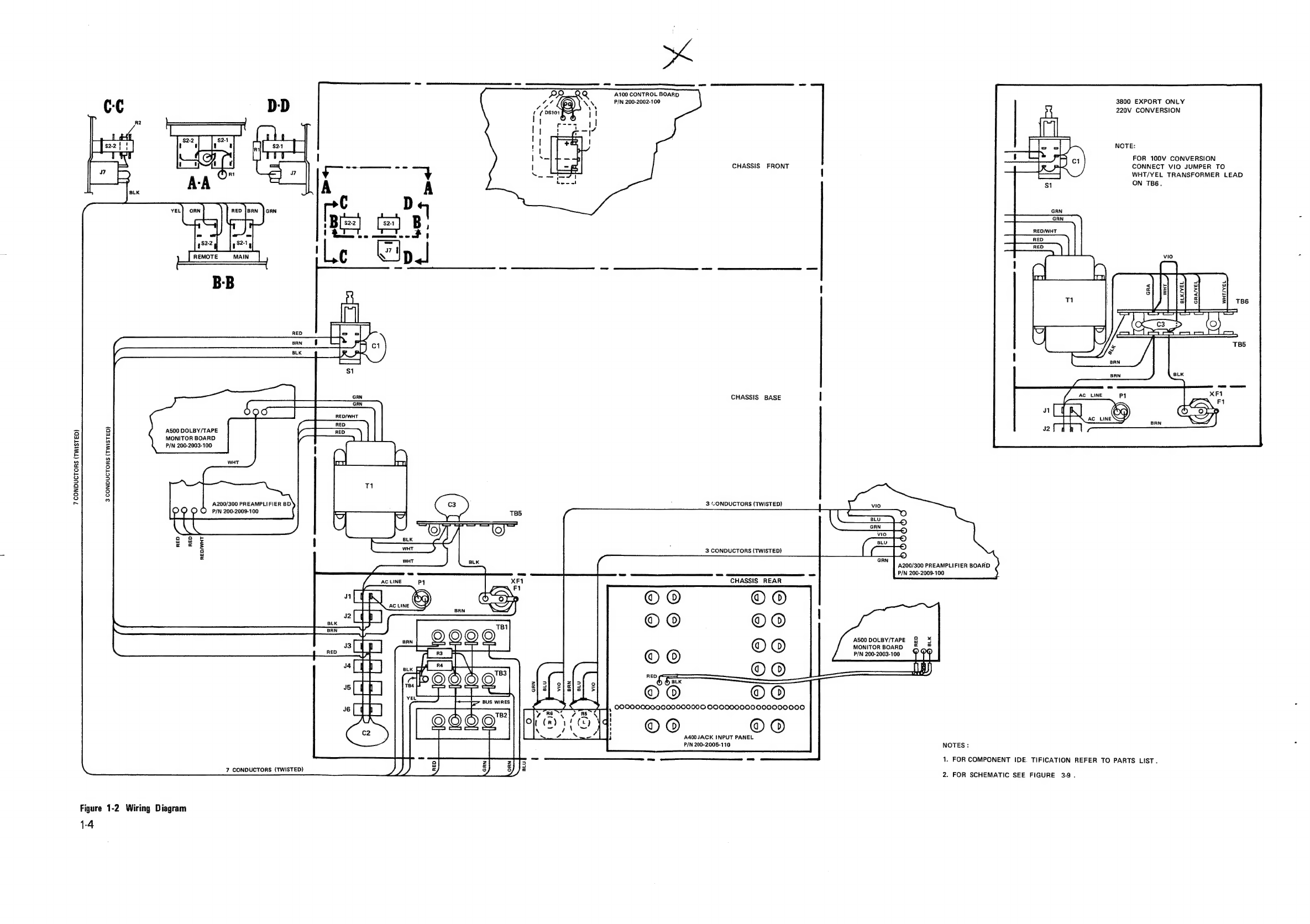
1-2
1-3
1-4
a
2-2
2-3
2-4
2-5
2-10
2-11
31
3-2
3-3
34
3-5
3-6
37
38
39
TABLE
NO.
1-1
1-1
2-1
2-2
2-2
2-2
LIST
OF
ILLUSTRATIONS
TITLE
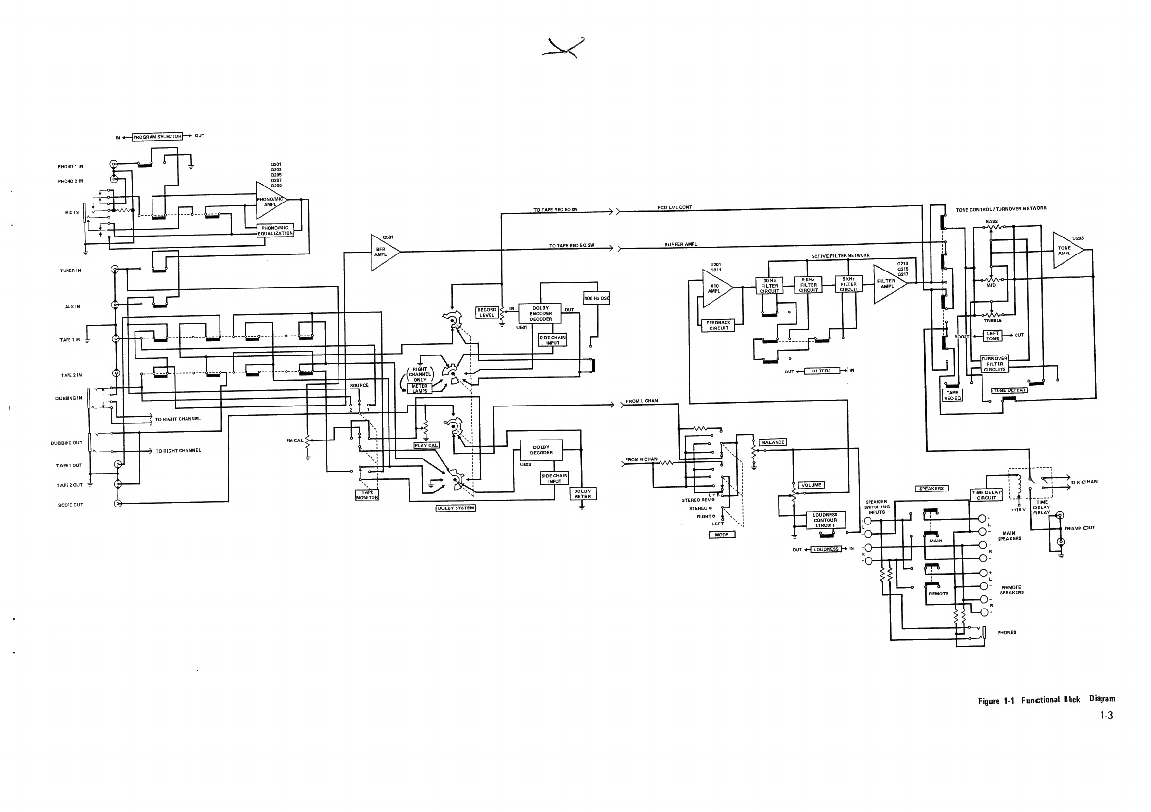
Functional
Block
Diagram...
02.0.0.
cece
ce
cece
eect
eeeeunuuuee
Wiring
Diagrarnts
ieee
ocd
5
sace
vrs
a
ets
dent
die
eit
ey
wee
oo
S
sack
daiwa
Shaiara
leas
Meese
Dolby
NR
Circuit
Signal
Processing
Diagram
...........
0.00
cece
eee
eees
Dolby
NR
Circuit
Signal
Processing
Diagram
(continued)
...............0005
AC
Power
Control
Box
Connection
Diagram...
.
0.0...
ccc
cee
cece
cece
eceees
Test
Equipment
Connection
Diagram,
Preamplifier
Circuits............200e005
RIAA
Equalization
Curve
and
Standard
.........
ccc
cc
cece cece
cee
cceceaeeue
Active
Filter
Network
Characteristics
.....
0.0.0.
0c
cece
cece
ce
ceuuvetvvenee
Dolby
Frequency
Response,
Flat
Mode
...........cccc
sec
e
ccc
eeaueceesees
Dolby
Frequency
Response,
Encode
Mode..........cccceuccecucevcececece
Dolby
Frequency
Response,
Decode
Mode..........00ccccececccecsavasecs
Repacking
Illustration...
0.0...
ccc
cc
cece
cee
ence
ne
eeeenseueenes
Front
Panel
Controls
and
Indicators...
1...
..
2c.
cece
cece
ccc
cence
een
eeaes
Rear
Panel
Jacks
and
Connectors
....
0.0...
cs
ccc
eee
e
cece
neces
eeeenauens
Disassembly
/
Reassembly
Diagram....
2.0...
0c.
ceca
cece
cc
ccecectcecece
Control
Board
Diagram,
Circuit
Side...
..
0...
ccc
cc
eee
eee
ne
eeaee
Preamplifier
Board
Diagram,
Circuit
Side.
......
0...
cece
eae
eee
eee
neeee
Dolby
-
Tape
Monitor
Board,
Circuit
Side...
..
2...
cee
ee
cee
cece
ee
Tape
Equalization
-
Tone
Defeat
Board,
Circuit
Side...........
ccc
cece
ee
aces
Tone
Oscillator
-
Dolby
Meter
Board,
Circuit
Side....
00...
cc
cee
eee
eee
eee
Schematic
Diagram
........
0.
cece
cece
ccc
ete
e
ee
eee
ence
nee
nnnneege
TITLE
Recommended
Test
Equipment............ccee
cece
ccc
eccuuuceveueneaue
Trouble
Analysis...
2.0.2.0...
ccc
cece
cece
ence
een
ccceeeeeeeauvuunnue
PAGE
1-3
1-4
1-5
1-6
2-2
2-2
2-5
2-6
2-6
3-14
314
PAGE
1-8
1-9
2-3
213
214
215