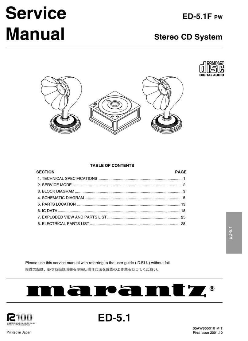
Marantz ED-5.1F PW User manual

ED-5.1
05AW855010 MIT
First Issue 2001.10
Service
Manual
R
Please use this service manual with referring to the user guide ( D.F.U. ) without fail.
Printed in Japan
ED-5.1F PW
Stereo CD System
TABLE OF CONTENTS
SECTION PAGE
1. TECHNICAL SPECIFICATIONS .............................................................................. 1
2. SERVICE MODE ...................................................................................................... 2
3. BLOCK DIAGRAM .................................................................................................... 3
4. SCHEMATIC DIAGRAM ........................................................................................... 5
5. PARTS LOCATION ................................................................................................ 13
6. IC DATA..................................................................................................................18
7. EXPLODED VIEW AND PARTS LIST .................................................................... 25
8. ELECTRICAL PARTS LIST .................................................................................... 28
Printed on 100% Recycled Paper
ED-5.1
All manuals and user guides at all-guides.com
all-guides.com

MARANTZ DESIGN AND SERVICE
Using superior design and selected high grade components, MARANTZ company has created the ultimate in stereo sound.
Only original MARANTZ parts can insure that your MARANTZ product will continue to perform to the specifications for which
it is famous.
Parts for your MARANTZ equipment are generally available to our National Marantz Subsidiary or Agent.
ORDERING PARTS :
Parts can be ordered either by mail or by Fax.. In both cases, the correct part number has to be specified.
The following information must be supplied to eliminate delays in processing your order :
1. Complete address
2. Complete part numbers and quantities required
3. Description of parts
4. Model number for which part is required
5. Way of shipment
6. Signature : any order form or Fax. must be signed, otherwise such part order will be considered as null and void.
SHOCK, FIRE HAZARD SERVICE TEST :
CAUTION : After servicing this appliance and prior to returning to customer, measure the resistance between either primary AC
cord connector pins ( with unit NOT connected to AC mains and its Power switch ON ), and the face or Front Panel of product and
controls and chassis bottom.
Any resistance measurement less than 1 Megohms should cause unit to be repaired or corrected before AC power is applied, and
verified before it is return to the user/customer.
Ref. UL Standard No. 1492.
In case of difficulties, do not hesitate to contact the Technical
Department at above mentioned address.
010620MIT
USA
MARANTZ AMERICA, INC
MARANTZ AMERICA, INC.
1100 MAPLEWOOD DRIVE
ITASCA, IL. 60143
USA
PHONE : 630 - 741 - 0300
FAX : 630 - 741 - 0301
BRAZIL
PHILIPS DA AMAZONIA IND. ELET. ITDA
CENTRO DE INFORMACOES AO
CEP 04698-970
SAO PAULO, SP, BRAZIL
PHONE : 0800 - 123123
(Discagem Direta Gratuita)
FAX : +55 11 534. 8988
JAPAN
Technical
MARANTZ JAPAN, INC.
35- 1, 7- CHOME, SAGAMIONO
SAGAMIHARA - SHI, KANAGAWA
JAPAN 228-8505
PHONE : +81 42 748 1013
FAX : +81 42 741 9190
EUROPE / TRADING
MARANTZ EUROPE B.V.
P.O.BOX 80002, BUILDING SFF2
5600 JB EINDHOVEN
THE NETHERLANDS
PHONE : +31 - 40 - 2732241
FAX : +31 - 40 - 2735578
TECHNICAL AUDIO GROUP PTY, LTD
558 DARLING STREET,
BALMAIN, NSW 2041,
AUSTRALIA
PHONE : 61 - 2 - 9810 - 5300
FAX : 61 - 2 - 9810 - 5355
CANADA
LENBROOK INDUSTRIES LIMITED
633 GRANITE COURT,
PICKERING, ONTARIO L1W 3K1
CANADA
PHONE : 905 - 831 - 6333
FAX : 905 - 831 - 6936
AUSTRALIA
QualiFi Pty Ltd,
24 LIONEL ROAD,
MT. WAVERLEY VIC 3149
AUSTRALIA
PHONE : +61 - (0)3 - 9543 - 1522
FAX : +61 - (0)3 - 9543 - 3677
NEW ZEALAND
WILDASH AUDIO SYSTEMS NZ
14 MALVERN ROAD MT ALBERT
AUCKLAND NEW ZEALAND
PHONE : +64 - 9 - 8451958
FAX : +64 - 9 - 8463554
THAILAND
MRZ STANDARD CO.,LTD
746 - 754 MAHACHAI ROAD.,
WANGBURAPAPIROM, PHRANAKORN,
BANGKOK, 10200 THAILAND
PHONE : +66 - 2 - 222 9181
FAX : +66 - 2 - 224 6795
TAIWAN
PAI- YUING CO., LTD.
6 TH FL NO, 148 SUNG KIANG ROAD,
TAIPEI, 10429, TAIWAN R.O.C.
PHONE : +886 - 2 - 25221304
FAX : +886 - 2 - 25630415
MALAYSIA
WO KEE HONG ELECTRONICS SDN. BHD.
SUITE 8.1, LEVEL 8, MENARA GENESIS,
NO. 33, JALAN SULTAN ISMAIL,
50250 KUALA LUMPUR, MALAYSIA
PHONE : +60 3 - 2457677
FAX : +60 3 - 2458180
AMERICAS
SUPERSCOPE TECHNOLOGIES, INC.
MARANTZ PROFESSIONAL PRODUCTS
2640 WHITE OAK CIRCLE, SUITE A
AURORA, ILLINOIS 60504 USA
PHONE : 630 - 820 - 4800
FAX : 630 - 820 - 8103
AUSTRALIA
KOREA
MK ENTERPRISES LTD.
ROOM 604/605, ELECTRO-OFFICETEL, 16-58,
3GA, HANGANG-RO, YONGSAN-KU, SEOUL
KOREA
PHONE : +822 - 3232 - 155
FAX : +822 - 3232 - 154
SINGAPORE
WO KEE HONG DISTRIBUTION PTE LTD
130 JOO SENG ROAD
#03-02 OLIVINE BUILDING
SINGAPORE 368357
PHONE : +65 858 5535 / +65 381 8621
FAX : +65 858 6078
All manuals and user guides at all-guides.com

1
1. TECHNICAL SPECIFICATIONS
CD Player Section
D/A conversion ......................................................................................................................................... 1 bit DAC
Wow & flutter ..............................................................................................................................Precision of quartz
Horn Section
Speaker .................................................................................................................................... 5.0 cm (8 ohms) x 2
Dynamic type
Output jack .............................................................................................................................. 3.5 mm 4P mini-jack
Dimensions (W x H x D) .................................................................................................... 172 x 290 x 170 mm x 2
Weight ...................................................................................................................................................... 0.9kg x 2
Amplifire Section
Maximun output power ........................................................................................................................... 6 W (EIAJ)
S/N ................................................................................................................................................................. 80 dB
Power Consumption ........................................................................................................................................ 19 W
Power Requirement .............................................................................................................. AC 100 V, 50 / 60 Hz
Dimensions (W x H x D) ............................................................................................................ 172 x 90 x 172 mm
Weight ............................................................................................................................................................ 1.9 kg
Accessories
3.5 mm mini-plug audio cable ............................................................................................................................... 1
Specifications subject to change without prior notice.
All manuals and user guides at all-guides.com

2
2. SERVICE MODE
Player
Service Mode
Service Mode b-0000 0000 Build Software Build
LCD Test PLAY CD Test
CD Test Laser Test Spindle Test Pickup Test
Service Mode STOP Reset
CD Test PLAY LCD Test CD Test
Off
Laser Test Pickup Test Spindle Test Laser Test NEXT
Laser Test PREV On Off On
Pickup Test PREV Off Off
r
Spindle Test PREV Clockwise Counte Clockwise Off
Clockwise
Stop No Disc NEXT PREV STOP PLAY
3
NEXT+PREV+
STOP
Stop
Stop
NEXT
Play
PlayPlay
RESET
OFF
ON
LCD TEST
CD TEST
LASER
PICKUP SPINDLE
RESET NEXT
NEXT
PREV
PREV
PREV
PREV
PREV PREV
PREV
OUT
IN
OFF
CW
CCW
All manuals and user guides at all-guides.com

3 4
3. BLOCK DIAGRAM
All manuals and user guides at all-guides.com

5 6
4. SCHEMATIC DIAGRAM
All manuals and user guides at all-guides.com
all-guides.com

7 8
All manuals and user guides at all-guides.com

910
All manuals and user guides at all-guides.com

11 12
GND
+5.6V
TDA7056A TDA7056A
DTC114TS
12.4V GND 12.4V
GND GND GND
GND
GNDGND
GND
GNDGND
GND GND
GNDGND
GND
GNDGNDGND
NJM78M05
GNDGND
+5.0V
+10.5V
S4VB20
GND
GNDGNDGND GNDGND
+12.4V
GND EARTH
GND GND
1/50v
1k
33k
3300p
10/16v
1k
3300p
33k
6.8
22000p
6.822000p
6.8
22000p
22000p 6.8
0.022
0.022
1 1/4w
2200/16v
100/6.3v
0.022
0.022
22000p
100/16v
0.01
J701
Q701 Q703
Q704
JJ31
C703
R701
R703
C705
C701
R702
C706
R704
J704
U029
U028
R715
C715
R714
C714
R711
C711
C713 R713
J707
J801
C811
C812
D811
D812D814
D813
R811
C813
Q801
C814
J803
F001
J802
C801
D801
C802
C804
C815
C810
J804
JV01
J852
U852
U851
J851
U855
S851
U854
C851
U853
JJ11
N001
W001
JJ11
N001
RV01
L801
C702
JJ30
9
8
7
6
5
4
3
2
1
9
8
7
6
5
4
3
2
1
56781234 9 56781234 9
1
2
3
1
2
3
4
3
2
1
6
5
4
3
2
1
2
13
1
2
34
3
2
1
6
5
4
3
2
1
3
2
1
3
2
1
1
2
12
1
2
1
10
2
1
10
2
2
3
1
123
45678
+5V
(8 OHM)
(8 OHM)
+
-
JJ12
SP UNIT
SP UNIT
JJ12
-
+
PV01
P701
MUTE
SENC
RMCH
LMCH
L CH
GND
R CH
GND
+6V
CD UNIT
L CH
R CH
AUDIO OUT L CH
AUDIO OUT R CH
L CH AMP R CH AMP
0V
2.2V
0.6V
0V
5.8V
0V
5.9V
0V
0V
0.9V
0V
0.6V
5.8V
0V
5.9V
0V
AC 8.8V
AC 8.8V
AC 10.3V
N.C N.C
RED
RED
WHITE
GREEN
WHITE
U 120V
/02 230V
C802
F,U 3300UF/16V
2200UF/25V/02,K,KK
3.15A/125VF,U
F001
/02,K,KK T2.5A/250V
L801 PRI.WIRE COLOR
WHITEF,U
BLUE
/02
K,KK
BROWN
RED
RED
BROWN
123
F 100V
All manuals and user guides at all-guides.com

13 14
5. PARTS LOCATION (Component Side)
QU04
PS01
All manuals and user guides at all-guides.com

Q404
Q410
Q409 Q252 Q401 Q251 Q402
Q203
Q204 Q202 Q403 Q201 Q411 QU06
Q406
Q405
Q407
QU03 Q408 QU01 QU03 QU02
PS01
15 16
PARTS LOCATION (Solder Side)
All manuals and user guides at all-guides.com
all-guides.com

17 18
P701
PV01
QU01 Q803 Q721 Q704
Q703
Q802 Q806
Q701
Q801
Q702
6. IC DATA
Block Diagram
Pinning Pin Configuration
Q251/252:TDA7073A
All manuals and user guides at all-guides.com

19
Q301/303:TDA7506
Block Diagram
Pinning
All manuals and user guides at all-guides.com

20
Q201:SAA7372
Block Diagram
All manuals and user guides at all-guides.com

21
All manuals and user guides at all-guides.com

22
Q402/403/404:TDA1308
Block Diagram
Pinning Pin Configuration
All manuals and user guides at all-guides.com
all-guides.com

23 24
QU01:TMP87CM21
No Name Function I/O Purpose
1 Vss GND - GND
2 XOUT Crystal O 8MHz
3 XIN Crystal I 8MHz
4 RESET Active (L) I Reset Mi-Com
5 P22/XTOUT I/O
6 P21/XTIN I/O
7 TEST TEST I GND
8 P20/INT5/STOP 3Bits I/O Port I/O
9 P40/INT3/TC3 8Bits I/O Port I/O IR-IN
10 P41/PWM/PDO 8Bits I/O Port I/O
11 P42/SCK1 8Bits I/O Port I/O
12 P43/SI1 8Bits I/O Port I/O
13 P44/SO1 8Bits I/O Port I/O
14 P45/SCK2 8Bits I/O Port I/O
15 P46/SI2 8Bits I/O Port I/O
16 P47/SO2 8Bits I/O Port I/O
17 P10/INT0 8Bits Programmable I/O Port I/O
18 P11/INT1 8Bits Programmable I/O Port I/O
19 P12/INT2/TC1 8Bits Programmable I/O Port O CD Module Power On/Off
20 P13/DVO 8Bits Programmable I/O Port O Laser On/Off
21 P14/PPG 8Bits Programmable I/O Port I Play Mode b1
22 P15/TC2 8Bits Programmable I/O Port I Play Mode b2
23 P16 8Bits Programmable I/O Port O CD-RW (L)
24 P17 8Bits Programmable I/O Port O MUTE
Pin Function
No Name Function I/O Purpose
25 P30 5Bits I/O Port I/O
26 P31 5Bits I/O Port I/O PLAY
27 P32 5Bits I/O Port I/O STOP
28 P33 5Bits I/O Port I/O NEXT
29 P34 5Bits I/O Port I/O PREV
30 P50/AIN0 8Bits Programmable I/O Port I/O CD Module SILD
31 P51/AIN1 8Bits Programmable I/O Port I/O CD Module RAB
32 P52/AIN2 8Bits Programmable I/O Port I/O CD Module SCL
33 P53/AIN3 8Bits Programmable I/O Port I/O CD Module SDA
34 P54/AIN4 8Bits Programmable I/O Port I/O CD Module RES. CD7
35 P55/AIN5 8Bits Programmable I/O Port I/O Door SW
36 P56/AIN6 8Bits Programmable I/O Port I/O SENC
37 P57/AIN7 8Bits Programmable I/O Port I/O
38 VASS Reference GND I
39 VAREF Reference Voltage for A/D Conversion I
40 VDD GND I
41 SEG31/P70 I/O
42 SEG30/P71 I/O
43 SEG29/P72 I/O
44 SEG28/P73 I/O
45 SEG27/P74 I/O
46 SEG26/P75 I/O
47 SEG25/P76 I/O
48 SEG24/P77 I/O
49 SEG23/P60 I/O
50 SEG22/P61 I/O
51 SEG21/P62 I/O
52 SEG20/P63 I/O
53 SEG19/P64 I/O
54 SEG18/P65 I/O
55 SEG17/P66 I/O
56 SEG16/P67 I/O
57 SEG15/P90 I/O
58 SEG14/P91 CAR, JAZZ, ROCK, Battery-B I/O
59 SEG13/P92 6a, 6b, 6c, Battery-A I/O
60 SEG12/P93 6d, 6e, 6f, 6g I/O
61 SEG11 5a, 5b, 5c, REPEAT O
62 SEG10 5d, 5e, 5f, 5g O
63 SEG9 4a, 4b, 4c, : O
64 SEG8 4d, 4e, 4f, 4g O
65 SEG7 3a, 3b, 3c, PROGRAM O
66 SEG6 3d, 3e, 3f, 3g O
67 SEG5 2a, 2b, 2c, RESUME O
68 SEG4 2d, 2e, 2f, 2g O
69 SEG3 1a, 1b, 1c, SHUFFLE O
70 SEG2 1d, 1e, 1f, 1g O
71 SEG1 L, R O
72 SEG0 VIDEO, PBC, KARAOKE O
73 COM3 O
74 COM2 O
75 COM1 O
76 COM0 O
77 VLC LCD Power O VDD-VLC=3V
78 N.C O
79 N.C O
80 N.C. O
Pin Assignment
All manuals and user guides at all-guides.com

25 26
8. EXPLODED VIEW AND PARTS LIST
5128
3X8( U)
x4
5128
2X6( U)
x5
037B
5128
2X6( U)
x2
5128
3X8( U)
x4
5159
3X8( A)
x2
5128
3X8( U)
x4
P70 1
L801
S85 1
027B
5110
3X8( U)
x3
(035B)
033B
CASE SUB ASSY.
045Bx2
5128
3X12( U)
x4
062B
5110
3X8( U)
x2
040B
038B ( 034B) x4
022B
046B
PU01
028B
W001
PV01
025B
L
( 006B)
011B
( 013B) x2
(015B)
001B
002B
003B
002Mx3
005B
(016B)
( 014B)
( 010B) x4
(007B)
( 009B)
017B
000B
TOP CASE A ASSY.
001M
5128
3X8( U)
011G
( 018B)
(008B)
( 012B)
(023B)
(024B)
(021B)
MAR K
MATERIAL/FINISH
STEEL/ COPPER
STEEL/ BL ACK
(A)
(U)
PARTS NAME
STYLE
5110 +B.H.M.SCREW
+B. H. TAP TITE SCREW( B TYPE)
5128
SYMBOL
5159 +B. H. TAP TI TE SCREW( S TYPE)
002D
004D
005D
011D
011D
003D
014D
020D
012D
019Dx4
021D
5128
3X8( U)
x3
5128
3X8( U)
x4
5128
3X8( U)
x4
N0 0 1
022Dx4
001D
010D
013D
A002
JJ11
F001
002D and 003D
must be adhered.
001B - 003B
must be adhered.
All manuals and user guides at all-guides.com

27
NOTE : "nsp" PART IS LISTED FOR REFERENCE ONLY, MARANTZ WILL NOT SUPPLY THESE PARTS.
POS.
NO
VERS.
COLOR
PART NO.
(FOR PCS) DESCRIPTION PART NO.
(MJI)
POS.
NO
VERS.
COLOR
PART NO.
(FOR PCS) DESCRIPTION PART NO.
(MJI)
000B CASE A SUB ASSY (P.WHITE) 207N064510
001B LID DIS (CLEAR) 332K257020
002B BUSH-UP (P.WHITE) 332K067330
003B BUSHING, -DOWN
(P.WHITE CLEAR LID) 332K259310
005B ESCUTCHEON,
SHEET (P.WHITE) 332K063350
006B CASE, TOP COVER (CD)
P.WHITE nsp
007B TRAY (CD) nsp
008B WINDOW LCD nsp
009B SENSOR LENS nsp
010B LEG, BUFFER FOR LID nsp
011B VOLUME KNOB (WHITE) 332K154310
012B HINGE BUTTON (SKIP) nsp
013B SILVER FOR BUTTON SKIP nsp
014B HINGE BUTTON (PLAY/STOP) nsp
015B SILVER FOR 014B (STOP) nsp
016B SILVER FOR 014B (PLAY) nsp
017B LEAF BUTTON 332K270030
018B MASK nsp
021B LED LENS nsp
022B SPACER,
(TOP CASE FRONT R SIDE) nsp
023B STICKER,
ADHESIVE FOR WINDOW nsp
024B STICKER,
ADHESIVE FOR LENS (2 TYPE) nsp
025B CASE, (CD) P.WHITE 332K064050
027B COIL SPRING 332K115010
028B 4822 532 60948 AC CORD BUSH (2271) 450H259010
033B CASE A2 SUB ASSY (P.WHITE) 332K064650
034B LEG (BUFFER) nsp
037B 4822 410 60343 BUTTON, POWER KNOB 058J270030
038B HEAT SINK nsp
040B BOTTOMWEIGHT T=1.6BLACK 207N008010
062B LCD HOLDER 323K271010
001D HORN RING (P.WHITE) 352K353110
002D HORN STAND L(P.WHITE) 352K128110
003D HORN STAND R(P.WHITE) 352K128120
004D COLLAR AIR (P.WHITE) 352K055110
005D STAND TABLE (WHITE) 352K004110
010D PUNCHING NET (WHITE) 352K202110
011D SPK BRACKET 352K160010
013D INSULATOR FOR PROTECTOR nsp
014D PROTECTOR, SILENCER nsp
019D LEG CUSHION 332K057010
020D NUT nsp
021D RUBBER RING nsp
022D INSULATOR, PEF SHEET 4X58 nsp
011G CONTACTOR nsp
001M CD MECHA(VAM2103) 452S304500
002M 4822 402 10897 BUFFER, DAMPER 359K056010
JJ11 3.5 MONO JACK
HSJ1400-01-010 YJ01004530
L801 MAINSTRANS 100V/120V TS15750010
N001 SPEAKER, 5CM 8
Ω
5W QK00502090
W001 A.C MAINS CORD YC01900270
PACKING
001T USER GUIDE 352K851110
A002 CONNECT CORD,
MONO MINI JACK 4P ZD01505020
NOT STANDARD SPARE
PARTS
001S PACKING CASE,
ED-5 (1 COLOR) 352K801110
002S CUSHION, L&R 352K809010
All manuals and user guides at all-guides.com

28
8. ELECTRICAL PARTS LIST
The suppliers and their type numbers of fusible resistors
are as follows;
1. KOA Corporation
Part No. (MJI) Type No. (KOA) Description
NH05 ×××140 RF25S × ×××ΩJ(±5% 1/4W)
NH05 ×××120 RF50S × ×××ΩJ(±5% 1/2W)
NH85 ×××110 RF73B2A × ×××ΩJ(±5% 1/10W)
NH95 ×××140 RF73B2E × ×××ΩJ(±5% 1/4W)
2. Matsushita Electronic Components Co., Ltd
Part No. (MJI) Type No. (MEC) Description
NF05 ×××140 ERD-2FCJ ×××(±5% 1/4W)
RF05 ×××140
NF02 ×××140
ERD-2FCG
×××(±2% 1/4W)
RF02 ×××140
Examples ;
Resistance value
0.1 Ω .... 001 10 Ω .... 100 1 kΩ .... 102 100 kΩ .... 104
0.5 Ω .... 005 18 Ω .... 180 2.7 kΩ .... 272 680 kΩ .... 684
1 Ω .... 010 100 Ω .... 101 10 kΩ .... 103 1 MΩ .... 105
6.8 Ω .... 068 390 Ω .... 391 22 kΩ .... 223 4.7 MΩ .... 475
ASSIGNMENT OF COMMON PARTS CODES.
RESISTORS
R : 1) GD05 × × × 140, Carbon film fixed resistor, ±5% 1/4W
R : 2) GD05 × × × 160, Carbon film fixed resistor, ±5% 1/6W
Examples ;
Resistance value
0.1 Ω .... 001 10 Ω .... 100 1 kΩ .... 102 100 kΩ .... 104
0.5 Ω .... 005 18 Ω .... 180 2.7 kΩ .... 272 680 kΩ .... 684
1 Ω .... 010 100 Ω .... 101 10 kΩ .... 103 1 MΩ .... 105
6.8 Ω .... 068 390 Ω .... 391 22 kΩ .... 223 4.7 MΩ .... 475
Note : Please distinguish 1/4W from 1/6W by the shape of parts
used actually.
CAPACITORS
C : CERAMIC CAP.
3) DD1 × ×××370, Ceramic capacitor
Disc type
Temp.coeff.P350 N1000, 50V
Examples ;
Tolerance (Capacity deviation)
±0.25 pF .... 0
±0.5 pF .... 1
±5% .... 5
Tolerance of COMMON PARTS handled here are as follows :
0.5 pF 5 pF .... ±0.25 pF
6 pF 10 pF .... ±0.5 pF
12 pF 560 pF .... ±5%
Capacity value
0.5 pF .... 005 3 pF .... 030 100 pF .... 101
1 pF .... 010 10 pF .... 100 220 pF .... 221
1.5 pF .... 015 47 pF .... 470 560 pF .... 561
C : CERAMIC CAP.
4) DK16 × × × 300, High dielectric constant ceramic
capacitor
Disc type
Temp.chara. 2B4, 50V
Examples ;
Capacity value
100 pF .... 101 1000 pF ....102 10000 pF .... 103
470 pF .... 471 2200 pF ....222
C : 5) ELECTROLY CAP. ( ), 6) FILM CAP. ( )
5) EA × × × × × ×10, Electrolytic capacitor
One-way lead type, Tolerance ±20%
Examples ;
Capacity value
0.1 µF....104 4.7 µF .... 475 100 µF ....107
0.33 µF....334 10 µF ....106 330 µF ....337
1 µF....105 22 µF .... 226 1100 µF ....118
2200 µF ....228
Working voltage
6.3V....006 25V ....025
10V .... 010 35V ....035
16V .... 016 50V ....050
6) DF15 × × × 350 Plastic film capacitor
DF15 × × × 310 One-way type, Mylar ±5% 50V
DF16 × × × 310 Plastic film capacitor
One-way type, Mylar ±10% 50V
Examples ;
Capacity value
0.001 µF (1000 pF) ....... 102 0.1 µF....104
0.0018 µF ........................ 182 0.56 µF ....564
0.01 µF........................ 103 1 µF....105
0.015 µF ........................ 153
: 1) The above CODES ( R , R , C , C and
C ) are omitted on the schematic diagram in some
case.
2) On the occasion, be confirmed the common parts on
the parts list.
3) Refer to “Common Parts List” for the other common
parts (RI05, DD4, DK4).
➀
➁
Capacity value
Tolerance
➃
Capacity value
Resistance value
➄Working voltage
Capacity value
➆Capacity value
NOTE
NOTE ON SAFETY FOR FUSIBLE RESISTOR :
Resistance value Resistance value
(0.1 Ω−10 kΩ)
Resistance value Resistance value
ANT. : ANTENNA BATT. : BATTERY
CAP. : CAPACITOR CER. : CERAMIC
CONN. : CONNECTING DIG. : DIGITAL
HP : HEADPHONE MIC. : MICROPHONE
µ-PRO : MICROPROCESSOR REC. : RECORDING
RES. : RESISTOR SPK : SPEAKER
SW : SWITCH TRANSF. : TRANSFORMER
TRIM. : TRIMMING TRS. : TRANSISTOR
VAR. : VARIABLE X’TAL : CRYSTAL
ABBREVIATION AND MARKS
{
{
{
{
{
{
{
{
{
{
➂
➀
➁
➂
➃
➄
➅
➆
➅
NOTE ON SAFETY :
Symbol Fire or electrical shock hazard. Only original
parts should be used to replaced any part marked with
symbol . Any other component substitution (other
than original type), may increase risk of fire or electrical
shock hazard.
NOTE ON FUSE :
Regarding to all parts of parts code FS20xxx2xx, replace
only with Wickmann-Werke GmbH, Type 372 non glass type
fuse.
010728MIT
All manuals and user guides at all-guides.com
Other manuals for ED-5.1F PW
1
Table of contents
Other Marantz Stereo System manuals

Marantz
Marantz ZC4001 User manual

Marantz
Marantz MD110 User manual

Marantz
Marantz ED-5.1F PW User manual

Marantz
Marantz NR1506 User manual

Marantz
Marantz PMD221 User manual

Marantz
Marantz 3800 User manual

Marantz
Marantz ZC4001 Instruction Manual

Marantz
Marantz SA-11S1 User manual

Marantz
Marantz MD-19 User manual