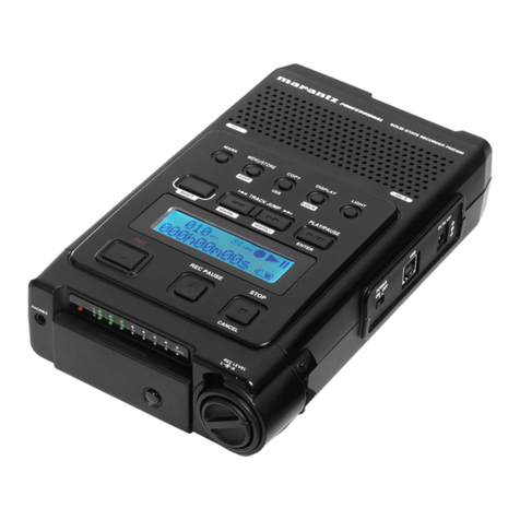
Marantz PMD650/N1B User manual

PMD650
409S855010 MIT
3120 785 22260
First Issue 2000.03
Service
Manual
PMD650 /N1B, /U1B, /F1B
R
PMD650
Printed in Japan
Please use this service manual with referring to the user guide ( D.F.U. ) without fail.
TABLE OF CONTENTS
SECTION PAGE
1. TECHNICAL SPECIFICATIONS ................................................................................................................. 1
2. SERVICE MODE ....................................................................................................................................... 2
3. MD MODULE(KML-252 with PCB) ELECTRICAL ADJUSTMENTS.................................................. 4
4. LCD CONTRAST ADJUSTMENT ......................................................................................................... 11
5. HOW TO DISASSEMBLE ...................................................................................................................... 11
6. WAVEFORMS ......................................................................................................................................... 17
7. BUGS AND PROBLEMS ........................................................................................................................ 18
8. WIRING DIAGRAM ................................................................................................................................. 19
9. BLOCK DIAGRAM .................................................................................................................................. 21
10. LEVEL DIAGRAM ................................................................................................................................... 23
11. SCHEMATIC DIAGRAM......................................................................................................................... 25
12. PARTS LOCATIONS .............................................................................................................................. 45
13. MICROPROCESSOR AND IC DATA ................................................................................................... 53
14. EXPLODED VIEW AND MECHANISM PARTS LIST......................................................................... 57
15. ELECTRICAL PARTS LIST ................................................................................................................... 59
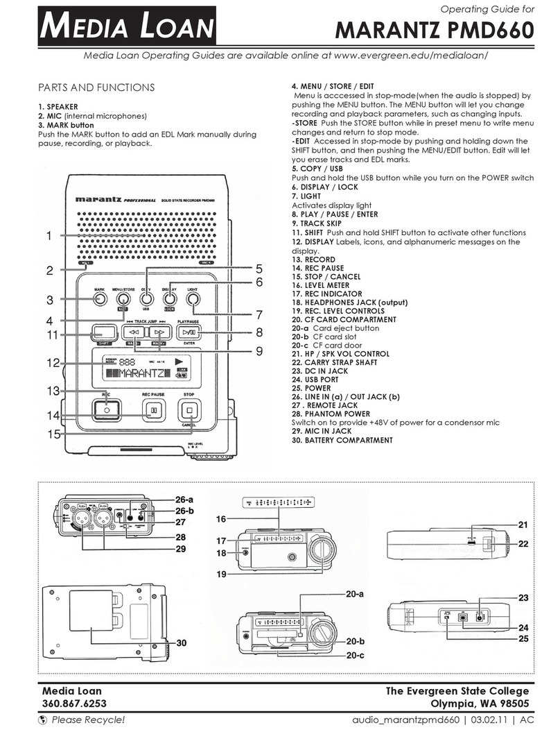
Portable Mini Disc Recorder
SOURCE
SP LP
OFF
ON
REC MODE
0dB
-15dB
MIC ATTEN
FLAT
ANC
REPEAT A-B/DEL TITLE CHAR ENTER
EDIT
BACKSPACE
-30dB MIC LINE
INPUT LEVEL
INPUT SELECT
STEREO
HP/SPK MODE
REC LEVEL
LSR
MANUAL
STEREO INTMIC L R
MONO (L ch)
ANALOG DIGITAL
LIMITER
ALC
PORTABLE MINIDISC RECORDER PMD650
POWER EJECT
MIC
DIGITAL RECORDING
DIGITAL IN REMOTE
(RC-5)
➀GND ➁HOT ➂COLD
MIC/LINE IN
PHANTOM
+48V
L R
OFF
ON
DISPLAY
REC PAUSE
LIGHT
KEY LOCK
PHONES
HP/SPK VOLUME
REC
LEVEL
L
R
REC/MARK
DC IN 12V
CHARGE
LINE OUT DIGITAL OUT
➂
➁
➀
L R
ON
OFF

MARANTZ DESIGN AND SERVICE
Using superior design and selected high grade components, MARANTZ company has created the ultimate in stereo sound.
Only original MARANTZ parts can insure that your MARANTZ product will continue to perform to the specifications for which
it is famous.
Parts for your MARANTZ equipment are generally available to our National Marantz Subsidiary or Agent.
ORDERING PARTS :
Parts can be ordered either by mail or by Fax.. In both cases, the correct part number has to be specified.
The following information must be supplied to eliminate delays in processing your order :
1. Complete address
2. Complete part numbers and quantities required
3. Description of parts
4. Model number for which part is required
5. Way of shipment
6. Signature : any order form or Fax. must be signed, otherwise such part order will be considered as null and void.
SHOCK, FIRE HAZARD SERVICE TEST :
CAUTION : After servicing this appliance and prior to returning to customer, measure the resistance between either primary AC
cord connector pins ( with unit NOT connected to AC mains and its Power switch ON ), and the face or Front Panel of product and
controls and chassis bottom.
Any resistance measurement less than 1 Megohms should cause unit to be repaired or corrected before AC power is applied, and
verified before it is return to the user/customer.
Ref. UL Standard No. 813.
In case of difficulties, do not hesitate to contact the Technical
Department at above mentioned address.
991207MIT
USA
MARANTZ AMERICA, INC
MARANTZ AMERICA, INC.
440 MEDINAH ROAD
ROSELLE, ILLINOIS 60172
USA
PHONE : 630 - 307 - 3100
FAX : 630 - 307 - 2687
BRAZIL
PHILIP DA AMAZONIA IND. ELET. ITDA
CENTRO DE INFORMACOES AO
CEP 04698-970
SAO PAULO, SP, BRAZIL
PHONE : 0800 - 123123
(Discagem Direta Gratuita)
FAX : +55 11 534. 8988
JAPAN
Technical
MARANTZ JAPAN, INC.
35- 1, 7- CHOME, SAGAMIONO
SAGAMIHARA - SHI, KANAGAWA
JAPAN 228-8505
PHONE : +81 42 748 1013
FAX : +81 42 741 9190
EUROPE / TRADING
MARANTZ EUROPE B.V.
P.O.BOX 80002, BUILDING SFF2
5600 JB EINDHOVEN
THE NETHERLANDS
PHONE : +31 - 40 - 2732241
FAX : +31 - 40 - 2735578
TECHNICAL AUDIO GROUP PTY, LTD
558 DARLING STREET,
BALMAIN, NSW 2041,
AUSTRALIA
PHONE : 61 - 2 - 9810 - 5300
FAX : 61 - 2 - 9810 - 5355
AUSTRALIA
JAMO AUSTRALIA PTY LTD
1 EXPO COURT, P.O. BOX 350
MT. WAVERLEY VIC 3149
AUSTRALIA
PHONE : +61 - 3 - 9543 - 1522
FAX : +61 - 3 - 9543 - 3677
THAILAND
MRZ STANDARD CO.,LTD
746 - 754 MAHACHAI ROAD.,
WANGBURAPAPIROM, PHRANAKORN,
BANGKOK, 10200 THAILAND
PHONE : +66 - 2 - 222 9181
FAX : +66 - 2 - 224 6795
TAIWAN
PAI- YUING CO., LTD.
6 TH FL NO, 148 SUNG KIANG ROAD,
TAIPEI, 10429, TAIWAN R.O.C.
PHONE : +886 - 2 - 25221304
FAX : +886 - 2 - 25630415
MALAYSIA
WO KEE HONG ELECTRONICS SDN. BHD.
SUITE 8.1, LEVEL 8, MENARA GENESIS,
NO. 33, JALAN SULTAN ISMAIL,
50250 KUALA LUMPUR, MALAYSIA
PHONE : +60 3 - 2457677
FAX : +60 3 - 2458180
AMERICAS
SUPERSCOPE TECHNOLOGIES, INC.
MARANTZ PROFESSIONAL PRODUCTS
2640 WHITE OAK CIRCLE, SUITE A
AURORA, ILLINOIS 60504 USA
PHONE : 630 - 820 - 4800
FAX : 630 - 820 - 8103
KOREA
MK ENTERPRISES LTD.
ROOM 604/605, ELECTRO-OFFICETEL, 16-58,
3GA, HANGANG-RO, YONGSAN-KU, SEOUL
KOREA
PHONE : +822 - 3232 - 155
FAX : +822 - 3232 - 154
SINGAPORE
WO KEE HONG (S) PTE LTD
WO KEE HONG CENTRE
NO.23, LORONG 8, TOA PAYOH
SINGAPORE 319257
PHONE : +65 2544555
FAX : +65 2502213
WILDASH AUDIO SYSTEMS NZ
14 MALVERN ROAD MT ALBERT
AUCKLAND NEW ZEALAND
PHONE : +64 - 9 - 8451958
FAX : +64 - 9 - 8463554
NEW ZEALAND
CANADA
LENBROOK INDUSTRIES LIMITED
633 GRANITE COURT,
PICKERING, ONTARIO L1W 3K1
CANADA
PHONE : 905 - 831 - 6333
FAX : 905 - 831 - 6936
AUSTRALIA

1
1. TECHNICAL SPECIFICATIONS
DIGITAL AUDIO SYSTEM
System
MiniDisc digital audio system
Disc
MiniDisc
Recording method
Magnetic field modulation, overwrite system
Reading method
Non-contact optical pickup (using semiconductor
laser)
Laser
Semiconductor laser
Laser Diode Properties
Material: GaAIAs
Wavelength: 780 nm
Record/playback time
SP mode (stereo): 80 minutes max.
LP mode (mono): 160 minutes max.
Revolutions
Approx. 400~900 rpm (CLV)
Error Correction
ACIRC (Advanced Cross Interleave Reed-solomon
Code)
Sampling frequency
44.1 kHz (32 kHz and 48 kHz signals converted to
44.1 kHz for recording)
Coding
ATRAC (Adaptive Transform Acoustic Coding)
Modulation System
EFM (Eight-to-Fourteen Modulation)
Number of channels
2 (stereo) or 1 (mono)
AUDIO SPECIFICATIONS
Frequency Response
20 Hz ~ 20 kHz
Signal-to-Noise Ratio (IEC-A weighted)
85 dB
Total Harmonic Distortion (at 0 VU)
0.02%
Dynamic Range
85 dB
Headphone Output Power
15 mW /32 ohms
Speaker Output Power
200 mW
Phantom Power
+48V, 5 mA
Inputs:
Reference level: -12 dB (Full scale 0 dB)
0 dBu = 0.775 Vrms
(MIC/LINE IN L/R)
Type: XLR (1: GND, 2: HOT, 3: COLD)
Input sensitivity (MIC): -60 dBu/9 kilohms
Input sensitivity (LINE): -20 dBu/47 kilohms
(DIGITAL IN)
Type: coaxial (RCA) jack
Input impedance: 75 ohms
Input level: 0.5 Vp-p
Outputs:
(LINE OUT L/R)
Type: RCA jack
Output level: 2 Vrms max./2 kilohms
(DIGITAL OUT)
Type: XLR
Output impedance: 110 ohms
Output level: 3.3 Vp-p
GENERAL
Power Supply
DC 13 V
Power Consumption
Recording: 5.5 W
Standby: 3.5 W
Dimensions (W x H x D)
264 x 54.8 x 185 mm
Weight (without battery)
1.3 kg (2 lbs. 14 oz.)
Accessories
AC adaptor :
DA600PMDF [F version]
DA600PMDU [U version]
Battery holder: 1
Carrying Strap: 1
User Guide: 1
Optional Accessories
AC adaptor :
74 DA600/02B, 74 DA600/05B : [N version]
NiCd Battery Pack (RB1100)
Carrying Case (74CLC650/09B)
Manufactured under license from Dolby Laboratories
Licensing Corporation.
Specifications subject to change without notice.

2
2. SERVICE MODE
2-1. PRECAUTIONS FOR USE OF SERVICE MODE
1. As loading related operations will be performed regardless
of the SERVICE MODE operations being performed, be sure
to check that the disc is stopped before setting and remov-
ing it. Even if the EJECT switch is slid while the disc is
rotating during continuous playback, etc., the disc will not
stop rotating. Therefore, it will be ejected while rotating. Be
sure to slide the EJECT switch after pressing the STOP
button and the rotation of disc is stopped.
2.The erasing-protection tab is not detected in the SERVICE
MODE. Therefore, when operating in the recording laser
emission mode and pressing the REC button, the recorded
contents will be erased regardless of the position of the
tab. When using a disc that is not to be erased in the SER-
VICE MODE, be careful not to ENTER the continuous re-
cording mode and traverse adjustment mode.
2-1-1. Recording Laser Emission Mode and Operating
Button
1. Continuous recording mode (CREC MODE)
2. Traverse adjustment mode (EFBAL ADJ)
3. Laser power adjustment mode (LDPWR ADJ)
4. Laser power check mode (LDPWR CHK)
5. When pressing the REC button.
2-2. HOW TO CONFIRM THE VERSION OF MICROPRO-
CESSOR
1. Confirm the product with Power Off.
2. While holding the FF/NEXT button, at the same time slide
the POWER switch.
3. And, the display shows "Ver=M@@S@@" (the version of
microprocessor. M:QL04 S:QU01).
4. When the display shows the version of microprocessor, slide
the POWER switch.Then the product will be in normal mode.
2-3. HOW TO SET THE SERVICE MODE
1. Confirm the product with Power Off.
2. While holding the PLAY/PAUSE button, at the same time
slide the POWER switch (At this moment the display shows
"Test Mode?" with blinking.).
3. Press the ENTER button.
4. It will be the service mode. Then the display shows “TEMP
ADJ” (the first content of table 2-2).
2-3. HOW TO STOP THE SERVICE MODE
Slide the POWER switch.
2.2.
2.2.
2. サービスモードサービスモード
サービスモードサービスモード
サービスモード
2‑1.2‑1.
2‑1.2‑1.
2‑1.サービスモード使用時の注意サービスモード使用時の注意
サービスモード使用時の注意サービスモード使用時の注意
サービスモード使用時の注意
1. ローディング関係の動作が、サービスモードの動作とは全く
無関係に働くので、必ずディスクが停止したことを確認して
からディスクの出し入れを行ってください。連続再生中等
ディスクが回転中にEJECTEJECT
EJECTEJECT
EJECTスイッチをスライドしてもディス
クの回転は停止しません。従って、ディスクが回転された状
態でイジェクトされますので、必ずSTOPSTOP
STOPSTOP
STOPボタンを押してディ
スクの回転が止まってからEJECTEJECT
EJECTEJECT
EJECTスイッチをスライドしてく
ださい。
2.サービスモード時は、誤消去防止つめの検出を行いません。そ
のため次の項目に示す" 記録用レーザーが発光するモード "
での作業および、
RECREC
RECREC
RECボタンを押した時は、つめの位置の関係
なくそれまでの記録内容が消去されます。従って、消去して
はいけないディスクをやむをえずサービスモード時に使用す
る場合、連続録音モードおよびトラバース調整モードに入ら
ないように注意してください。
2‑1‑1.2‑1‑1.
2‑1‑1.2‑1‑1.
2‑1‑1. 記録用レーザーが発光するモードおよびボタン操作記録用レーザーが発光するモードおよびボタン操作
記録用レーザーが発光するモードおよびボタン操作記録用レーザーが発光するモードおよびボタン操作
記録用レーザーが発光するモードおよびボタン操作
1.連続録音モード(CRECMODE)
2.トラバース調整モード(EFBALADJ)
3.レーザーパワー調整モード(LDPWRADJ)
4.レーザーパワー確認モード(LDPWRCHK)
5.RECREC
RECREC
RECボタンを押した時
2‑2.2‑2.
2‑2.2‑2.
2‑2. マイコンバージョンの確認方法マイコンバージョンの確認方法
マイコンバージョンの確認方法マイコンバージョンの確認方法
マイコンバージョンの確認方法
1.PowerOFF の状態にします。
2. まず、FF/NEXTFF/NEXT
FF/NEXTFF/NEXT
FF/NEXTボタンを押しながら、さらに、PowerONする
と、ディスプレイに「Ver=M@@S@@」とマイコンのバージョン
が表示されます。(M:QL04S:QU01)
3.マイコンバージョン表示のときは、一度PowerOFFするまで
通常動作になりません。
2‑3.2‑3.
2‑3.2‑3.
2‑3. サービスモードの設定方法サービスモードの設定方法
サービスモードの設定方法サービスモードの設定方法
サービスモードの設定方法
1.PowerOFF の状態にします。
2.まず、PLAYPLAY
PLAYPLAY
PLAYボタンを押しながら、次にPowerONすると、ディ
スプレイに「TestMode?」と点滅します。
3.ENTERENTER
ENTERENTER
ENTERボタンを押すとサービスモードになります。
4. この時、ディスプレイ表示は表 2‑2 の1 行目「TEMPADJ」が
表示されます。
2‑3.2‑3.
2‑3.2‑3.
2‑3.サービスモードの解除方法サービスモードの解除方法
サービスモードの解除方法サービスモードの解除方法
サービスモードの解除方法
PowerPower
PowerPower
PowerOFFします。以後通常動作になります。

3
2-4. BASIC OPERATIONS OF THE SERVICE MODE
All operations are performed using the STOP button, ENTER
button, and EDIT(<, >) buttons. The functions of these but-
tons are as follows.
Table 2-1.
Button Function
Changes parameters and modes.
ENTER button Finalizes input.
EDIT button
Stops operations.
STOP button
2-5. SELECTING THE SERVICE MODE
Nine SERVICE MODEs are selected by using the EDIT(<, >)
buttons.
Table 2-2.
Display Contents
TEMP ADJ Temperature compensation offset
adjustment
LDPWR ADJ Laser power adjustment
LDPWR CHK Laser power check
EFBAL ADJ Traverse (E-F balance) adjustment
FBI AS ADJ Focus bias adjustment
FBI AS CHK Focus bias check
CPLAY MODE Continuous playback mode
CREC MODE Continuous recording mode
EEP MODE Non-volatile memory mode (✱1)
•For detailed description of each adjustment mode, refer to
the " MD UNIT ELECTRICAL ADJUSTMENTS".
•If a different adjustment mode has been selected by mis-
take, press the STOP button to exit from it.
✱1: The EEP MODE is not used in servicing. If set acciden-
tally, press the STOP button immediately to exit it.
2-6. EEP MODE
This mode reads and writes the contents of the non-volatile
memory.
It is not used in servicing. If set accidentally, press the STOP
button immediately to exit it.
2-7. FUNCTIONS OF OTHER BUTTONS
Table 2-3.
Button Contents
The sled moves to the outer circumference
only when this is pressed.
The sled moves to the inner circumference
only when this is pressed.
Note : The erasing-protection tab in not detected during the
SERVICE MODE. Recording will start regardless of the
position of the erasing-protection tab when the REC
button is pressed.
2‑4.2‑4.
2‑4.2‑4.
2‑4.サービスモードの基本操作サービスモードの基本操作
サービスモードの基本操作サービスモードの基本操作
サービスモードの基本操作
全ての操作はSTOPSTOP
STOPSTOP
STOPボタン、ENTERENTER
ENTERENTER
ENTERボタンおよびEDIT(<,>)EDIT(<,>)
EDIT(<,>)EDIT(<,>)
EDIT(<,>)ボタ
ンので行います。
表2‑1 にそれぞれの機能を記します。
表2‑1
2‑5.2‑5.
2‑5.2‑5.
2‑5.サービスモードの選択サービスモードの選択
サービスモードの選択サービスモードの選択
サービスモードの選択
サービスモードは表2‑2に示す9項目があり、各テストモードの
選択は EDIT(<,>)EDIT(<,>)
EDIT(<,>)EDIT(<,>)
EDIT(<,>)ボタンで選択します。
表2‑2
•各調整モードの詳しい説明は、" MDユニット電気調整" の各項
目を参照してください。
•誤って別の調整モードに入ってしまった場合は、STOPSTOP
STOPSTOP
STOPボタン
を押しそのモードから抜けてください。
*1:EEPMODEは、各調整時自動処理されるので、このモード
を直接選択しないでください。誤ってこのモードに入って
しまった場合はすぐに、
STOPSTOP
STOPSTOP
STOPボタンを押してこのモードか
ら抜けてください。
2‑6.EEP2‑6.EEP
2‑6.EEP2‑6.EEP
2‑6.EEP モードモード
モードモード
モード
EEPモードは不揮発性メモリの内容の読み書きを行うモードです
が、このモードは各調整時自動処理されるので、このモードを直
接選択しないでください。
従って、誤ってこのモードに入ってしまった場合はすぐに、
STOPSTOP
STOPSTOP
STOP
ボタンを押してこのモードから抜けてください。
2‑7.2‑7.
2‑7.2‑7.
2‑7.その他のボタンの機能その他のボタンの機能
その他のボタンの機能その他のボタンの機能
その他のボタンの機能 表2‑3
注意注意
注意注意
注意::
::
:サービスモード時は、誤消去防止つめの検出を行いませ
ん。RECボタンを押すと誤消去防止つめの位置に関係な
く録音されますので注意してください。

4
3.3.
3.3.
3.MDMD
MDMD
MD
モジュールモジュール
モジュールモジュール
モジュール(KML‑252withPCB)(KML‑252withPCB)
(KML‑252withPCB)(KML‑252withPCB)
(KML‑252withPCB)電気調整電気調整
電気調整電気調整
電気調整
3‑1.3‑1.
3‑1.3‑1.
3‑1.レーザーダイオード発光確認時の注意レーザーダイオード発光確認時の注意
レーザーダイオード発光確認時の注意レーザーダイオード発光確認時の注意
レーザーダイオード発光確認時の注意
調整時にレーザーダイオードの発光を確認する場合は失明のおそ
れがありますので絶対に真上から覗かないでください。
3‑2.3‑2.
3‑2.3‑2.
3‑2.光ピックアップ取扱時の注意光ピックアップ取扱時の注意
光ピックアップ取扱時の注意光ピックアップ取扱時の注意
光ピックアップ取扱時の注意
光ピックアップ内のレーザーダイオードは非常に静電破壊し易い
ため、取扱時はフレキシブル基板のレーザータップを半田ブリッ
ジしてください。
コネクタから外す時は、事前に半田ブリッジをしてから外してく
ださい。またコネクタを差す前に半田ブリッジをとらないように
注意してください。また静電破壊を防止する対策を充分に行い作
業してください。フレキシブル基板は切れ易いので取扱に注意し
てください。
3‑3.3‑3.
3‑3.3‑3.
3‑3.調整時の注意調整時の注意
調整時の注意調整時の注意
調整時の注意
1.下記の部品を交換した時は、 印の調整、確認を下記表の順番
で行ってください。
注意:
以降の調整を行うには、下記の治具、測定器が必要です。
• レーザーパワーメータ(アドバンテストTQ8210)
• オプティカルセンサー(アドバンテストTQ82017)
• オシロスコープ
(プローブの CAL を行ってから測定してください。)
•ジッターメータ
•寒暖計
上記の治具、測定器がない場合には、調整済のMD モジュール
<Parts Number :ZZ409S3010> (5. 分解方法の Fig.15 を参照 )の
交換を行ってください。
3. MD MODULE(KML-252 with PCB)
ELECTRICAL ADJUSTMENTS
3-1. PRECAUTIONS FOR CHECKING LASER DIODE
EMISSION
To check the emission of the laser diode during adjustments,
never view directly from the top as this may cause loss of
eyesight.
3-2. PRECAUTIONS FOR USE OF OPTICAL PICK-UP
As the laser diode in the optical pick-up is easily damaged by
static electricity, solder the laser tap of the flexible board when
using it.
Before disconnecting the connector, de-solder first. Before
connecting the connector, be careful not to remove the sol-
der. Also take adequate measures to prevent-damage by static
electricity. Handle the flexible board with care as it breaks
easily.
3-3. PRECAUTIONS FOR ADJUSTMENTS
1. When replacing the following parts, perform the adjust-
ments and checks with in the order shown in the follow
ing table.
Notes:
The following tools and measuring devices are necessary for
the adjustments.
• Laser power meter ( TQ8210 )
• Optical sensor ( TQ82017 )
• Oscilloscope (Measure after pre-forming CAL of prove.)
• Jitter meter
• Thermometer
If you cannot prepare them, please replace the adjusted MD
module <Part Number : ZZ409S3010> (refer to "5. HOW TO
DISASSEMBLE Fig.15").
Optical pick-up flexible board

5
Table 3-1.
MD circuit
MD
board QU20
1.Temperature
compensation
offset ad
j
ustment
X
2.Laser power X
3.Traverse
ad
j
ustment X
4.Focus bias
ad
j
ustment X
5.Error rate check X
DQ10 QU01, QQ01,
QQ10, QQ50
MD Mechanism
KML-252
(001M)
2. Set the SERVICE MODE when performing adjustments.
After completing the adjustments, exit the SERVICE MODE.
3. Perform the adjustments in the order shown.
4. When observing several signals on the oscilloscope, etc.,
make sure that VC and ground do not connect inside the
oscilloscope.
(VC and ground will become short-circuited)
5. Test disc
Table 3-2
High reflection disc A-BEX, TMD-381, for audio
performance measurement
Low reflection disc Blank disc on market for
Rec/Play
Eccentricity disc A-BEX, TMD-311R, Confirm
Rec/Play operation
Surface distortion disc A-BEX, TMD-331R, Confirm
Rec/Play operation
3-4. CREATING CONTINUOUSLY RECORDED DISC
This disc is used in focus bias adjustment and error rate check.
The following describes how to create a continuous record-
ing disc.
1. Set the SERVICE MODE.
2. Insert a low reflection disc (blank disc) commercially avail-
able.
3. Use the EDIT(<, >) buttons and display "CREC MODE".
4. Press the ENTER button and display "CREC MID".
"CREC (0300)" is displayed and recording starts.
5. Complete recording within 5 minutes.
6. Press the STOP button and stop recording.
7. Slide the EJECT switch and remove the low reflection disc.
The above has been how to create a continuous recording
data for the focus bias adjustment and error rate check.
Note : Be careful not to apply vibration during continuous
recording.
3-5. TEMPERATURE COMPENSATION OFFSET
ADJUSTMENT
Save the temperature data at that time in the non-volatile
memory as 25 °C reference data.
Notes :
1. Usually, do not perform this adjustment.
表3‑1
QU20 DQ10 QU01,QQ01,QQ10,QQ50
MD Mechanism
KML-252
(001M)
2.調整はサービスモードにして行ってください。
調整終了後はサービスモードを解除してください。
3.調整は掲載順に行ってください。
4.オシロスコープ等で複数の信号を見る場合、VCとGND がオシ
ロスコープ内部で接続されないようにしてください。
(VC とGND がショートしてしまいます。)
5.テストディスク 表3‑2
3‑4.3‑4.
3‑4.3‑4.
3‑4.連続録音ディスクの作り方連続録音ディスクの作り方
連続録音ディスクの作り方連続録音ディスクの作り方
連続録音ディスクの作り方
このディスクはフォーカスバイアス調整および確認、エラーレー
ト確認において使用するディスクです。以下その連続録音ディス
クの作り方を記します。レーザーは通常、間欠発光ですが、連続
録音中は連続発光しています。
1.市販の低反射ディスク(ブランクディスク)を挿入する。
2.EDIT(<,>)EDIT(<,>)
EDIT(<,>)EDIT(<,>)
EDIT(<,>)ボタンを押して表示を" CRECMODE" にする。
3.ENTERENTER
ENTERENTER
ENTERボタンを押すと" CRECMID" になる。
"CREC0300" と表示し録音を始める(数字が変化する)。
4.5 分間以内に録音を終えてください。
5.STOPSTOP
STOPSTOP
STOP ボタンを押して録音を止める。
6.EJECTEJECT
EJECTEJECT
EJECTスイッチをスライドして低反射ディスクを取り出す。
以上でフォーカスバイアス調整および確認、エラーレート確認用
の連続録音ディスクを作ることができます。
注意注意
注意注意
注意::
::
:連続録音中は振動などが加わらないように注意してくだ
さい。
3‑5.3‑5.
3‑5.3‑5.
3‑5.温度補償オフセット調整温度補償オフセット調整
温度補償オフセット調整温度補償オフセット調整
温度補償オフセット調整
その時点の温度データを25 ℃基準データとして不揮発性メモリ
にセーブします。
注意注意
注意注意
注意::
::
:
1.通常、この調整は行わないでください。
2.この調整を行う際の周囲温度は22℃〜28℃の範囲で行うよ
うにしてください。また、セットの内部温度が周囲温度と同
じ22℃〜28 ℃の状態である電源投入直後に行ってください。
3.DQ01交換後は、部品の温度が十分周囲温度になってからこの調
整を行ってください。

6
2. Perform this adjustment in an ambient temperature of 22
°C to 28 °C. Perform it immediately after the power is turned
on when the internal temperature of the unit is the same as
the ambient temperature of 22 °C to 28 °C.
3. When DQ10 has been replaced, perform this adjustment
after the temperature of this part has become the ambient
temperature.
Adjusting Method:
1. Selected by Use the EDIT(<, >) buttons and display "TEMP
ADJ".
2. Press the ENTER button.The display shows "TEMP +25C".
By using the EDIT(<, >) buttons, set the current tempera-
ture.
3. To save the data, press the ENTER button.
4. When the ENTER button is pressed, "DATA SAVE" will be
displayed for 1 second, followed by "TEMP ADJ".
3-6. LASER POWER ADJUSTMENT
Connection:
Laser
power mater
Optical pick-up
objective lens
Adjusting Method:
1. Set the sensor disc of power meter into the MD mecha-
nism.
2. Selected by Use the EDIT(<, >) buttons and display "LDPWR
ADJ". (Laser power : for adjustment)
3. Press the ENTER button and display "LD 0.9 $ ". (Then
the pickup will move to inside automatically.)
4. Selected by Use the EDIT(<, >) buttons so that the reading
of the laser power meter becomes 0.88 to 0.92 mW.
Set the range control on the laser power meter to 10 mW,
then press the ENTER button to save the adjustment result
in the non-volatile memory. ("DATA SAVE" will be displayed
for a moment.)
5. Then "LD 7.0 $ " will be displayed.
6. Press the PLAY button, selected by Use the EDIT(<, >)
buttons so that the reading of the laser power meter be-
comes 6.95 to 7.05 mW, press the ENTER button and save
the adjustment result in the non-volatile memory. ("DATA
SAVE" will be displayed for a moment.)
Note : The emission stops after 10 seconds automatically.
When the adjustment resume, press the PLAY but-
ton.
7. Selected by Use the EDIT(<, >) buttons and display
"LDPWR CHK".
8. Press the ENTER button and display "LD 0.9 $ ".
Check that the reading of the laser power meter becomes
0.80 to 0.96 mW.
9. Press the ENTER button and display "LD 7.0 $ ".
Check that the reading of the laser power meter satisfy 6.95
to 7.05 mW.
調整方法調整方法
調整方法調整方法
調整方法::
::
:
1.EDIT(<,>)EDIT(<,>)
EDIT(<,>)EDIT(<,>)
EDIT(<,>)ボタンを押して表示を"TEMPADJ"にする。
2.ENTERENTER
ENTERENTER
ENTERボタンを押すと"TEMP+25"と表示される。その時EDITEDIT
EDITEDIT
EDIT
(<,>)(<,>)
(<,>)(<,>)
(<,>)ボタンを使って現在の室温に合わせる。
3. 温度表示を室温に合わせた後、
ENTERENTER
ENTERENTER
ENTERボタンを押すと入力した
データをEEPROMに書き込み、"DATASAVE"を1秒間表示して
から項目選択に戻ります。
3‑6.3‑6.
3‑6.3‑6.
3‑6.レーザーパワー調整および確認レーザーパワー調整および確認
レーザーパワー調整および確認レーザーパワー調整および確認
レーザーパワー調整および確認
接続接続
接続接続
接続::
::
:
Laser
power mater
Optical pick-up
objective lens
調整方法調整方法
調整方法調整方法
調整方法::
::
:
1.レーザーパワーメータのセンサーMDディスクをMDメカにセッ
トする。
2.EDIT(<,>)EDIT(<,>)
EDIT(<,>)EDIT(<,>)
EDIT(<,>)ボタンを押して表示を"LDPWRADJ" にする。(レー
ザーパワー:調整用)
3. ENTERENTER
ENTERENTER
ENTERボタンを押して表示を"LD0.9$ "にする。(この時、
ピックアップは自動的に最内周に移動する。)
4. レーザーパワーメータの読みが0.9mW±0.02mWになるよう
にEDIT(<,>)EDIT(<,>)
EDIT(<,>)EDIT(<,>)
EDIT(<,>)ボタンを押して調整する。次にレーザーパワー
メータのレンジつまみを10mW にセットしてから ENTERENTER
ENTERENTER
ENTERボタ
ンを押して不揮発性メモリに調整結果をセーブする。(この時、
一瞬"DATASAVE"と表示される。)
5.表示が "LD7.0$ "になる。
6. PLAYPLAY
PLAYPLAY
PLAYボタンを押して(レーザーが発光する)、レーザーパワー
メータの読みが7.0mW ±0.05mW になるようにEDIT(<,>)EDIT(<,>)
EDIT(<,>)EDIT(<,>)
EDIT(<,>)
ボタンを押して調整し、
ENTERENTER
ENTERENTER
ENTERボタンを押して不揮発性メモリ
に調整結果をセーブする。(この時、一瞬"DATASAVE"と表示さ
れる。)
注意注意
注意注意
注意::
::
:発光は、10 秒で自動的に停止しますが、その場合は
PLAYPLAY
PLAYPLAY
PLAYボタンを押して、調整を行ってください。
7. EDIT(<,>)EDIT(<,>)
EDIT(<,>)EDIT(<,>)
EDIT(<,>)ボタンを押して表示を"LDPWRCHK"にする。
8. ENTERENTER
ENTERENTER
ENTERボタンを押して表示を"LD0.9$ "にする。この時の
レーザーパワーメータの読みが0.9mW±0.02mWであること
を確認する。
9. ENTERENTER
ENTERENTER
ENTERボタンを押して表示を "LD7.0$ "にする。この時の
レーザーパワーメータの読みが7.0mW±0.05mWであること
確認する。
10.STOPSTOP
STOPSTOP
STOPボタンを押してレーザー発光を止める。表示は "LDPWR
CHK"に戻る。
STOPSTOP
STOPSTOP
STOPボタンはいつでも受け付け、レーザ発光を止めます。
3‑7.3‑7.
3‑7.3‑7.
3‑7.トラバーストラバース
トラバーストラバース
トラバース(E‑F(E‑F
(E‑F(E‑F
(E‑F バランスバランス
バランスバランス
バランス))
))
)調整調整
調整調整
調整
トラバース調整には、2種類のディスクで4つのデータをセーブ
します。
注意注意
注意注意
注意::
::
:記録済ディスクをこの調整に使用すると書き込み時デー
タが消去されます。
7
10. Press the STOP button and display "LDPWR CHK". and
stop the laser emission.
The STOP button is effective at all times to stop the laser
emission.
3-7. TRAVERSE (E-F BALANCE) ADJUSTMENT
Note 1 : Data will be erased during MO reading if a recorded
disc is used in this adjustment.
Note 2 : If the traverse waveform is not clear. connect the
oscilloscope as shown in the following figure so that
it can be seen more clearly.
Connection:
Osilloscope
(DC range)
JQ20 pin 3 (TEO)
330k
10p
+
-
JQ20 pin 2 (VC)
V : 0.1 V/div
H : 10 ms/div
( )
Adjusting Method:
1. Connect an oscilloscope to JQ20 pin 3 (TEO) and JQ20
pin 2 (VC) of the MD board (PQ01).
2. Load a low reflection disc (any available on the market).
(Refer to Note 1.)
3. Press the button or button and move the optical
pick-up outside the pit.
4. Use the EDIT(<, >) buttons and display "EFBAL ADJ".
5. Press the ENTER button and display "EFBAL MO".
(Laser power READ power/Focus servo ON/tracking servo
OFF/spindle (S) servo ON)
6. Press the ENTER button.
7. Use the EDIT(<, >) buttons so that the waveforms of the
oscilloscope becomes the specified value. (When the the
EDIT(<, >) buttons is Used, the " " of "MOr EFB= "
changes and the waveform changes.) In this adjustment,
waveform varies at intervals of approx. 2%. Adjust the wave-
form so that the specified value is satisfied as much as
possible. (MO read power traverse adjustment)
(Traverse Waveform)
specification : A = B
8. Press the ENTER button, and save the result of adjust-
ment to the non-volatile memory. ("DATA SAVE" will be
displayed for a moment.Then "MOw EFB= " will be dis-
played.) The optical pick-up moves to the pit area auto-
matically and servo is imposed.
9. Use the EDIT(<, >) buttons so that the waveforms of the
oscilloscope becomes the specified value. (When the the
EDIT(<, >) buttons is Used, the " " of "MOw EFB= "
changes and the waveform changes.) In this adjustment,
waveform varies at intervals of approx. 2%. Adjust the
waveform so that the specified value is satisfied as much
as possible.
接続接続
接続接続
接続::
::
:
Osilloscope
(DC range)
JQ20 pin 3 (TEO)
330k
10p
+
-
JQ20 pin 2 (VC)
V : 0.1 V/div
H : 10 ms/div
( )
調整方法調整方法
調整方法調整方法
調整方法::
::
:
1.オシロスコープをMD基板(PQ01)の JQ203 ピン(TEO)とJQ20
2ピン(VC)に接続する。
2.市販の低反射ディスク(ブランクディスク)を挿入する。(注意
.参照)
3. ボタン、 ボタンを押して光ピックアップをピット部よ
り外周に移動する。
4.EDIT(<,>)EDIT(<,>)
EDIT(<,>)EDIT(<,>)
EDIT(<,>)ボタンを押して表示を"EFBALADJ"にする。
5.ENTERENTER
ENTERENTER
ENTERボタンを押して表示を"EFBALMO"にする。
(これはレーザーパワー:READ パワー,フォーカスサーボ
:ON, トラッキングサーボ:OFF,スピンドル(S)サーボ:
ONの状態)
6. 再度、ENTERENTER
ENTERENTER
ENTERボタンを押します。
7. オシロスコープの波形が規格値になるように EDIT(<,>)EDIT(<,>)
EDIT(<,>)EDIT(<,>)
EDIT(<,>)ボ
タンを押して調整する。
(EDIT(<,>)EDIT(<,>)
EDIT(<,>)EDIT(<,>)
EDIT(<,>)ボタンを押すと、"MOrEFB= "の" " 数字が変
化し、波形も変化します。)
この調整は約2% 刻みで変化し、最も規格値に近づくように
調整する。
(MOリードパワートラバース調整)
(トラバース波形規格:A=B)
8. ENTERENTER
ENTERENTER
ENTERボタンを押して不揮発性メモリに調整結果をセーブす
る。(この時、一瞬 "DATASAVE"と表示される。)
その後に"MOwEFB= "と表示される。自動的にピット部の内
周まで光ピックアップが移動してサーボがかかる。
9.この時のオシロスコープの波形が規格値に近づくようにEDITEDIT
EDITEDIT
EDIT
(<,>)(<,>)
(<,>)(<,>)
(<,>)ボタンを押して調整する。
(EDIT(<,>)EDIT(<,>)
EDIT(<,>)EDIT(<,>)
EDIT(<,>)ボタンを押すと、"MOwEFB= "の" " 数字が変
化し、波形も変化します。)
この調整は約2%刻みで変化し、最も規格値に近づくように調
整する。
(MOライトパワートラバース調整)
(トラバース波形規格:A=B)
10.ENTERENTER
ENTERENTER
ENTERボタンを押して不揮発性メモリに調整結果をセーブす
る。(この時、一瞬 "DATASAVE"と表示される。)
その後"MOpEFB= "と表示される。

8
11. オシロスコープの波形が規格値になるように EDIT(<,>)EDIT(<,>)
EDIT(<,>)EDIT(<,>)
EDIT(<,>)ボ
タンを押して調整する。
(EDIT(<,>)EDIT(<,>)
EDIT(<,>)EDIT(<,>)
EDIT(<,>)ボタンを押すと、"MOpEFB= "の" " 数字が変
化し、波形も変化します。)
この調整は約 2% 刻みで変化し、最も規格値に近づくように
調整する。
(ピットトラバース調整)
(トラバース波形規格:A=B)
12.ENTERENTER
ENTERENTER
ENTERボタンを押して不揮発性メモリに調整結果をセーブす
る。(この時、一瞬"DATASAVE"と表示される。)
13.EJECTEJECT
EJECTEJECT
EJECTスイッチをスライドして低反射ディスクを取り出す。
14.テストディスク高反射ディスクA‑BEXTMD‑381を挿入する。
15.ENTERENTER
ENTERENTER
ENTERボタンを押して表示を"CDEFB= "にする。
16.再度、ENTERENTER
ENTERENTER
ENTERボタンを押します。自動的にサーボがかかりま
す。
17. オシロスコープの波形が規格値に近づくように EDIT(<,>)EDIT(<,>)
EDIT(<,>)EDIT(<,>)
EDIT(<,>)
ボタンを押して調整する。
(EDIT(<,>)EDIT(<,>)
EDIT(<,>)EDIT(<,>)
EDIT(<,>)ボタンを押すと、"CDEFB= "の" " 数字が変
化し、波形も変化します。)
この調整は約2%刻みで変化し、最も規格値に近づくように調
整する。
(トラバース波形規格:A=B)
18.ENTERENTER
ENTERENTER
ENTERボタンを押して不揮発性メモリに調整結果をセーブす
る。(この時、一瞬"DATASAVE"と表示される。)
その後に"EFBALADJ"と表示される。
19.EJECTEJECT
EJECTEJECT
EJECTスイッチをスライドしてテストディスク高反射ディス
ク A‑BEXTMD‑381 を取り出す。
3‑8.3‑8.
3‑8.3‑8.
3‑8.フォーカスバイアス調整フォーカスバイアス調整
フォーカスバイアス調整フォーカスバイアス調整
フォーカスバイアス調整
接続接続
接続接続
接続::
::
:
Jitter Meter
+
-
JQ20 1pin(RF)
JQ20 2pin(VC)
調整方法調整方法
調整方法調整方法
調整方法::
::
:
1.連続録音済ディスク("3-4. 連続録音ディスクの作り方"を参
照してください。)を挿入する。
2.EDIT(<,>)EDIT(<,>)
EDIT(<,>)EDIT(<,>)
EDIT(<,>)ボタンを押して表示を"FBIASADJ"にする。
3.ENTERENTER
ENTERENTER
ENTERボタンを押して表示を"a= "にする。
(Traverse Waveform)
specification : A = B
10. Press the ENTER button, and save the result of adjust-
ment to the non-volatile memory. ("DATA SAVE" will be
displayed for a moment. Then "MOp EFB= " will be dis-
played.)
11. Use the EDIT(<, >) buttons so that the waveforms of the
oscilloscope becomes the specified value. (When the the
EDIT(<, >) buttons is Used, the " " of "MOp EFB= "
changes and the waveform changes.) In this adjustment,
waveform varies at intervals of approx. 2%. Adjust the
waveform so that the specified value is satisfied as much
as possible.
(MO write power traverse adjustment)
(Traverse Waveform)
specification : A = B
12. Press the ENTER button, and save the result of adjust-
ment to the non volatile memory. ("DATA SAVE" will be
displayed for a moment.) Then "MOp EFB= " will be dis-
played.
13. Slide the EJECT switch and remove the low reflection
disc.
14. Load the test disc. ( High reflection disc TMD-381 )
15. Press the ENTER button and display "CD EFB= ".
16. Press the ENTER button. Servo is imposed automatically.
17. Use the EDIT(<, >) buttons so that the waveforms of the
oscilloscope becomes the specified value. (When the the
EDIT(<, >) buttons is Used, the " " of "CD EFB= "
changes and the waveform changes.) In this adjustment,
waveform varies at intervals of approx. 2%. Adjust the
waveform so that the specified value is satisfied as much
as possible.
(Traverse Waveform)
specification : A = B

9
18. Press the ENTER button, and save the result of adjust-
ment to the non-volatile memory. ("DATA SAVE" will be dis-
played for a moment. Then "EFBAL ADJ" will be displayed.)
19. Press the EJECT switch and remove the test disc. ( High
reflection disc TMD-381 )
3-8. FOCUS BIAS ADJUSTMENT
Connection:
Jitter Meter
+
-
JQ20 1pin(RF)
JQ20 2pin(VC)
Adjusting Method:
1. Load a continuously recorded disc (Refer to "3-4. Creating
MO Continuously Recorded. Disc".).
2. Use the EDIT(<, >) buttons and display "FBIAS ADJ".
3. Press the ENTER button and display "a = ".
4. Press the ">" of the EDIT(<, >) button and find the focus
bias value at which the reading of the jitter meter becomes
27 ns to 30 ns. (Refer to note 2.) If the reading of the jitter
meter is over 30 ns, press the "<" of the EDIT(<, >) button.
It will be down.
5. Press the ENTER button and display "b = ".
6. Press the "<" of the EDIT(<, >) button and find the focus
bias value at which the reading of the jitter meter becomes
27 ns to 30 ns. (Refer to note 2.) If the reading of the jitter
meter is over 30 ns, press the ">" of the EDIT(<, >) button.
It will be down.
Note : If the sarvo is out and It stops to adjust, press the STOP
button. The display will show "ADJ CANCEL", and the
display return to "FBIAS ADJ".
7. Press the ENTER button, and save the result of adjustment
to the non-volatile memory. ("DATA SAVE" will be displayed
for a moment. ) Then "c = " will be displayed.
8. Press the DISPLAY button and display "C1 AD " and
check that the C1 error rate is below 50 and ADER is 00.
Then press the STOP button. The first four digits indicate
the C1 error rate, the two digits after indicate ADER.
9. If the reading of the jitter meter is over 28 ns, press the
STOP button ("FBIAS ADJ" will be displayed.) and adjust it
again.
10. Press the STOP button and slide the EJECT switch to
remove the continuously recorded disc.
Note 1 : The relation between the C1 error and jiter meter is as
shown in the following figure. Find points aand bin
the following figure using the above adjustment. The
focal point position
c
is automatically calculated from
points
a
and
b
.
Note 2 : As the jiter meter changes, perform the adjustment
using the average vale.
4.EDIT(>)EDIT(>)
EDIT(>)EDIT(>)
EDIT(>)ボタン(必ず、>)を押してジッターメータ値が27nS
〜30nSになるフォーカスバイアス量を見つける。(注意2.参
照)30nSを超えたときのみ(<)(<)
(<)(<)
(<)ボタンで少し下げる。(a点側の
ジッターの最大値を設定)
5.ENTERENTER
ENTERENTER
ENTERボタンを押して表示を"b="にする。
6.EDIT(<)EDIT(<)
EDIT(<)EDIT(<)
EDIT(<)ボタン(必ず、<)を押してジッターメータ値が27nS
〜30nSになるフォーカスバイアス量を見つける。(注意2.参
照)30nSを超えたときのみ(>)(>)
(>)(>)
(>)ボタンで少し下げる。(b点側の
ジッターの最大値を設定)
注意注意
注意注意
注意::
::
:サーボが外れたとき及び調整を中止するときは、STOPSTOP
STOPSTOP
STOP
ボタンを押すと"ADJCANCEL"を表示して(調整データは
セーブされない。)、その後表示は"FBIASADJ"に戻る。
(項目選択)
STOPSTOP
STOPSTOP
STOPボタンはいつでも受け付け、調整を止めます。
7.ENTERENTER
ENTERENTER
ENTER ボタンを押して不揮発性メモリに調整結果をセーブす
る。(この時、一瞬 "DATASAVE"と表示される。)
その後"c="と表示される。(c 点は自動調整)
8.この時、DISPLAYDISPLAY
DISPLAYDISPLAY
DISPLAYボタンを押して、"C1 AD "と表示する。
C1エラーレート表示が50以下でADERが00であることを確認
して STOPSTOP
STOPSTOP
STOPボタンを押す。最初の4桁の数字がC1 エラーレー
ト、後の2 桁の数字が ADER を示す。
9.ジッターメータ値が28nS以上の時はSTOPSTOP
STOPSTOP
STOPボタンを押して再
度、調整をする。"FBIASADJ"に戻る。(項目選択)
10.STOPSTOP
STOPSTOP
STOPボタンを押し、次にEJECTEJECT
EJECTEJECT
EJECTスイッチをスライドして連続
録音済ディスクを取り出す。
注意注意
注意注意
注意::
::
:
1.C1エラーとジッターメータ値の関係を示すと下図のようにな
ります。上記調整で下図の
aa
aa
a
,
bb
bb
b
点を見つけます。合焦点位置
cc
cc
c
点は
aa
aa
a
,
bb
bb
b
点から自動的に計算し求めます。
2.ジッターメータ値は変動しますので、平均値を読み調整を行
うようにしてください。
Error
Focus bias value
(F.BIAS)
bca
30ns
3‑9.3‑9.
3‑9.3‑9.
3‑9.エラーレート確認エラーレート確認
エラーレート確認エラーレート確認
エラーレート確認
3‑9‑1.3‑9‑1.
3‑9‑1.3‑9‑1.
3‑9‑1.高反射ディスクエラーレート確認高反射ディスクエラーレート確認
高反射ディスクエラーレート確認高反射ディスクエラーレート確認
高反射ディスクエラーレート確認
確認方法確認方法
確認方法確認方法
確認方法::
::
:
1.高反射ディスク A‑BEXTMD‑381 を挿入する。
2.EDIT(<,>)EDIT(<,>)
EDIT(<,>)EDIT(<,>)
EDIT(<,>)ボタンを押して表示を"CPLAYMODE"にする。
3.ENTERENTER
ENTERENTER
ENTER ボタンを押すと表示が 1秒間"CPLAYMID"となった後、
表示が"C1 AD "に変わる。
4.C1エラーレートが20 以下であることを確認する。
5.STOPSTOP
STOPSTOP
STOP ボタンを押して再生を止め、EJECTEJECT
EJECTEJECT
EJECTスイッチをスライド
して高反射ディスクを取り出す。

10
Error
Focus bias value
(F.BIAS)
bca
30ns
3-9. ERROR RATE CHECK
3-9-1. High Reflection Disc Error Rate Check
Checking Method:
1. Load a test disc.( High reflection disc TMD-381 )
2. Use the EDIT(<, >) buttons and display "CPLAY MODE" .
3. Press the ENTER button and the display shows "CPLAY MID"
for 1 second. Then "C1 AD " is displayed.
4. Check that the C1 error is below 20.
5. Press the STOP button, stop playback, slide the EJECT
switch, and remove the test disc. ( High reflection disc TMD-
381 )
3-9-2. Low Reflection Disc Error Rate Check
Checking Method:
1. Load a continuously recorded disc (Refer to "3-4. Creating
MO Continuously Recorded Disc".).
2. Use the EDIT(<, >) buttons and display "CPLAY MODE".
3. Press the ENTER button and the display shows "CPLAY MID"
for 1 second. Then "C1 AD " is displayed.
4. If the C1 error is below 50, check that ADER is 00.
5. Press the STOP button, stop playback, slide the EJECT switch
and remove the continuously recorded disc.
3-10. FOCUS BIAS CHECK
Change the focus bias and check the focus tolerance amount.
Checking Method:
1. Load a continuously recorded disc (Refer to " 3-4. Creating
Continuously Recorded Disc".).
2. Use the EDIT(<, >) buttons and display "FBIAS CHECK".
3. Press the ENTER button and display "c = ".
4. Press the DISPLAY button and display "C1 AD " .
The first four digits indicate the C1 error rate, the two digits
after indicate ADER. Check that the C1 error is below 50 and
ADER is 00.
5. Press the STOP button, next slide the EJECT switch, and
remove the continuously recorded disc.
3‑9‑2.3‑9‑2.
3‑9‑2.3‑9‑2.
3‑9‑2.低反射ディスクエラーレート確認低反射ディスクエラーレート確認
低反射ディスクエラーレート確認低反射ディスクエラーレート確認
低反射ディスクエラーレート確認
確認方法確認方法
確認方法確認方法
確認方法::
::
:
1.連続録音済ディスク("3-4. 連続録音ディスクの作り方"を参照
してください。)を挿入する。
2.EDIT(<,>)EDIT(<,>)
EDIT(<,>)EDIT(<,>)
EDIT(<,>)ボタンを押して表示を"CPLAYMODE"にする。
3.ENTERENTER
ENTERENTER
ENTERボタンを押すと表示が1秒間"CPLAYMID"となった後、表
示が"C1 AD "に変わる。
4.C1エラーレートが50以下でADERが00であることを確認する。
5.STOPSTOP
STOPSTOP
STOPボタンを押して再生を止め、
EJECTEJECT
EJECTEJECT
EJECTスイッチをスライドし
て低反射ディスクを取り出す。
3‑10.3‑10.
3‑10.3‑10.
3‑10.フォーカスバイアス確認フォーカスバイアス確認
フォーカスバイアス確認フォーカスバイアス確認
フォーカスバイアス確認
フォーカスバイアス量を変化させフォーカストレランス量の確認
をします。
確認方法確認方法
確認方法確認方法
確認方法::
::
:
1.連続録音済ディスク("3-4. 連続録音ディスクの作り方"を参照
してください。)を挿入する。
2. EDIT(<,>)EDIT(<,>)
EDIT(<,>)EDIT(<,>)
EDIT(<,>)ボタンを押して表示を"FBIASCHK"にする。
3. ENTERENTER
ENTERENTER
ENTERボタンを押して表示を"c="にする。次にDISPLAYDISPLAY
DISPLAYDISPLAY
DISPLAYボ
タンを押すと"C1 AD "を表示する。最初の4桁の数字が
C1エラーレート、後の2桁の数字が ADER を示す。この時のC1
エラーレートが50以下でADER が00 であることを確認する。
4. STOPSTOP
STOPSTOP
STOPボタンを押して再生を止め、
EJECTEJECT
EJECTEJECT
EJECTボタンをスライドして
連続録音済ディスクを取り出す。

11
4. LCD CONTRAST ADJUSTMENT
1. Connect the TEST POINT (See below) with the tester.
2. Turn the variable resistor RF09 so that the reading of the
testor becomes 7.0 V ± 0.1 V and conform the contrast of
the LCD becames maximum.
5. HOW TO DISASSEMBLE
1. Taking the MD module apart
1) Remove 7 screws as shown in Fig.1.
2) Remove the battery cover.
3) Remove 4 screws as shown in Fig.2.
4) Remove 2 screws from both sides as shown in Fig.3 and
Fig.4.
4.LCD4.LCD
4.LCD4.LCD
4.LCD輝度電圧調整輝度電圧調整
輝度電圧調整輝度電圧調整
輝度電圧調整
1.LCDモジュールとメイン基板をペアーとして以下の調整をお
こなってください。
2.TESTPOINT にテスターを接続し、輝度電圧測りながらボ
リューム RF09 の抵抗値を調整する。
3.LDCを正面から見て、コントラストが最大になることを確認
しながら輝度電圧を7.0V ± 0.1V に調整する。
5.5.
5.5.
5.分解方法分解方法
分解方法分解方法
分解方法
1.MD1.MD
1.MD1.MD
1.MDモジュールの外し方モジュールの外し方
モジュールの外し方モジュールの外し方
モジュールの外し方
1) 下図1に示すビス7本を外します。
2) バッテリーカバーを外します。
3) 下図2に示すビス4本を外します。
4) 下図3〜4に示す両サイドのビス計2本を外します。
<Fig.1 Position of 7 screws>
<Fig.2 Position of 4 screws>
<Fig.3 Position of screw> <Fig.4 Position of screw>

12
5) Remove the front panel, holding it and pushing down with
thumb as shown in Fig.5 and Fig.6.
6) Remove 4 screws as shown in Fig.7.
7) Remove 5 connectors and screw as shown in Fig.8. And
remove the top case.
8) Remove 4 screws as shown in Fig.9.
5) フロントパネルを下図5 〜6 の位置を指で押さえながら外し
ます。
6) 下図7に示すビス2本を外します。
7) トップケースを持ち上げます。下図8 に示す5つのコネクタ
とビスを外し、トップケースを外します。
8) 下図9に示すMDメカユニット部分のビス4本を外します。
<Fig.7 Position of 4 screws>
<Fig.9 Position of 4 screws>
<Fig.8 Position of connectors>
<Fig.5 Holding position> <Fig.6 Removing the front panel>

13
9) Remove the MD unit part.
10) Remove 2 screws as shown in Fig.11.
11) Lift up the MD lid. Remove the hinge.
12) Remove the MD lid. Remove the lever of EJECT and
POWER and the cables.
Notes:
When the MD module is replaced, please confirm the version
of µ-Processors, QU01 and QL04 (refer to "7. BUGS AND
PROBLEMS").
9) MDメカユニット部分を取り外します(図10)。
10)下図11のビス2本外します。
11)MDの蓋を持ち上げます(図12)。HINGEを外します(図13)。
12)MDの蓋を取り外します。EJECT、POWERスイッチレバーと
ケーブル2本を外します(図14)。
注意:
MDモジュールを交換する際は、2つのマイコン(QU01、QL04)の
バージョンを確認してください。詳しくは、7.不具合対応を参
照してください。
<Fig.14 Removed the MD module> <Fig.15 The MD module (Part Number : ZZ409S3010)>
<Fig.11 Position of 2 screws>
<Fig.12 lifting up the MD lid> <Fig.13 Removing the hinge>
<Fig.10 The part of the MD unit>

14
2. Taking The MD PCB apart
13) Remove 3 cables and screw as shown in Fig.16.
14) Turn over the MD PCB.
15) Solder in the position as shown in Fig.18. Then remove
the connector.
3. Taking the MD mechanism a part
16) Remove 4 screws as shown in Fig.19.
2.MD2.MD
2.MD2.MD
2.MD基板の外し方基板の外し方
基板の外し方基板の外し方
基板の外し方
13)下図16に示すコネクタ3つ、ビス1本を外します。
14)基板を裏返します(図17)。
15)下図18に示す部分に半田を付けます。それから、コネクタ
を外します。
3.MD3.MD
3.MD3.MD
3.MDメカの外し方メカの外し方
メカの外し方メカの外し方
メカの外し方
16)下図19のビス4本を外します。
<Fig.17 Turning over the MD PCB>
<Fig.19 Position of 4 screws>
<Fig.18 Soldering position>
<Fig.16 Position of 3 cables and screws>

15
17) Remove the MD mechanism.
4. The spare parts of MD mechanism (KML-252)
17)MDメカを外します。
4.MD4.MD
4.MD4.MD
4.MDメカメカ
メカメカ
メカ(KML‑252)(KML‑252)
(KML‑252)(KML‑252)
(KML‑252)のスペアパーツのスペアパーツ
のスペアパーツのスペアパーツ
のスペアパーツ
<Fig.21> <Fig.22>
<Fig.23>
SW1
MO1
SW2
SW3
No. PART No. DESCRIPTION
MO1
*
MM001030R MOTOR FOR EJECT LOCK
SW1
*
SP000970R SWITCH FOR PICK-UP
SW2
*
SP000950R SWITCH (SHORT)
SW3
*
SP000960R SWITCH (LONG)
<Fig.20 The MD mechanism>

16
5. Caution on reassemble
18) When reattaching the lid, position the hook as shown in
Fig.19.
19) Reconnect cables as shown in Fig.20.
5.5.
5.5.
5.組立時の注意組立時の注意
組立時の注意組立時の注意
組立時の注意
18)MDの蓋を取り付ける時、金具を図19に示すように合せます。
19)図20に示す様に配線します。
<Fig.24 Position of the hook>
<Fig.25 Reconnecting cables>

17
6. WAVEFORMS
6.6.
6.6.
6.
波形図波形図
波形図波形図
波形図
QQ90 ( PLAY MODE )
C2M (1pin)
X=2V Y=2µs
QQ90 ( PLAY MODE )
C2P (2pin)
X=2V Y=2µs
QQ10
QQ10
QQ10
QQ10
QQ50
QQ50
QQ50
QQ50
QQ50
QU01
QU01
(X1)
(X2)
2.8 Vp-p
2.2 Vp-p
2.8223 MHz
22.5782 MHz
11.2891 MHz

18
QL04 ( STOP MODE )
E (36pin)
RW (35pin)
RS (346pin)
X=2V Y=50µs
QD20 ( STOP MODE )
LRCK (10pin)
ADDT (12pin)
X=2V Y=5µs/d
QD20 ( REC MODE )
DADT (15pin)
X=2V Y=50µs
QL04 ( PLAY START MODE )
CTS (11pin)
RTS (7pin)
RXD (5pin)
X=2V Y=50µs
TXD
(6pin)
02 02 U 200 S20 V55 OK NG OK NG OK
00 03 N 200 S20 V54 NG NG NG NG NG
00 04 N 200 S20 V54 NG NG NG NG NG
00 N 100 S20 V54 OK NG NG NG OK
02 N 115 S20 V55 NG NG OK NG NG
02 N 35 S20 V55 OK NG OK NG OK
02 N 200 S20 V55 OK NG OK NG OK
02 U 100 S20 V55 OK NG OK NG OK
03 N 300 S22 V57 OK NG OK OK OK
03 U 100 S22 V57 OK NG OK OK OK
04 F 100 S23 V58 OK OK OK OK OK
04 08 F 100 S23 V58 OK OK OK OK OK
05 09 N 160 S24 V59 OK OK OK OK OK
03 10 U 200 S22 V57 OK NG OK OK OK
04 N 250 S23 V58 OK OK OK OK OK
04 U 100 S24 V59 OK OK OK OK OK
05
04 F 100 S23 V58 OK OK OK OK OK
12 S24 V59
SERVICE
CODE LOT Version Quantity
µ-Processor
version Symptom
MD
(QU01)
Main
(QL04)
Phantom
*1
REC DATE
*2
MONO/ST sel.
*3
80min MD
*4
P-ON No read
*5
05
06
07
11
Symptom Symptom description Solution description
Phantom Power line (+48V) will
be shut down when press the
PLAY button while RECORDING.
Remove the transistor QP33 (PCB
PK01).
MONO/ST (at the STOP mode )
switch will not work correctly
while LP recordin
g
.
Replace microprocessor QL04
(PCB PK01) to latest version one.
Recorded DATE/TIME data by
PMD650 has no compatibility
with other MD recorders.
Replace microprocessors QU01
(PCB PQ01) and QL04 (PCB
PK01
)
to latest version ones.
Disc detect will not work. Short soldering pins (pin33 and
pin34) of micrprocessor QU01.
P-ON No read *5
Time indication can be shown
only 160min while LP mode
recording with 80min MD disc.
Replace microprocessors QU01
(PCB PQ01) and QL04 (PCB
PK01) to latest version ones.
Phantom *1
REC DATE *2
MONO/ST sel. *3
80 min MD *4
S20 First version
S22
For solution of 80min MD disc time
indication : pairing with Main
microprocessor V57 or later is
necessary.
S23
For solution of REC date/time
compatibility with other MD recorder
: pairing with Main microprocessor
V58 or later is necessary.
V54 First version
V55 For solution of MONO/STEREO
selector problem
V57
For solution of 80min MD disk time
indication : pairing with MD
microprocessor S22 or later is
necessary.
V58
For solution of REC date/time
compatibility with other MD recorder
: pairing with Main microprocessor
S23 or later is necessar y.
MD (QU01)
µ-processor
HU409ST00F
996500001345
Main (QL04)
µ-processor
HU409ST10F
996500003625
7. BUGS AND PROBLEMS
When the symptoms appear as shown in the Table 7-1, solve
by referring to Table 7-1, Table 7-2 and Table 7-3. Other
symptoms caused by µ-processors (QU01, QL04) will be
published via "Service Bulletin".
7.7.
7.7.
7.不具合対応不具合対応
不具合対応不具合対応
不具合対応
下記のTable7‑1のような不具合があった場合には、Table7‑1、
Table7‑2、Table7‑3を参考に対応してください。Table7‑3に
記載されていないServicecode及びLOTの不具合については、今
後発行されるサービスブリテンを参照して下さい。
Table 7-1 Symptom and Solution
Table 7-2 µ-processor
Table 7-3 Service cord and Lot
This manual suits for next models
3
Table of contents
Other Marantz Voice Recorder manuals

Marantz
Marantz PMD-706 User manual

Marantz
Marantz PMD570 User manual

Marantz
Marantz PMD660 User manual

Marantz
Marantz PMD561 User manual

Marantz
Marantz PMD620 User manual

Marantz
Marantz PMD620MKII User manual

Marantz
Marantz PMD680 User manual

Marantz
Marantz PMD660 User manual

Marantz
Marantz PMD660 User manual

Marantz
Marantz PMD671 User manual