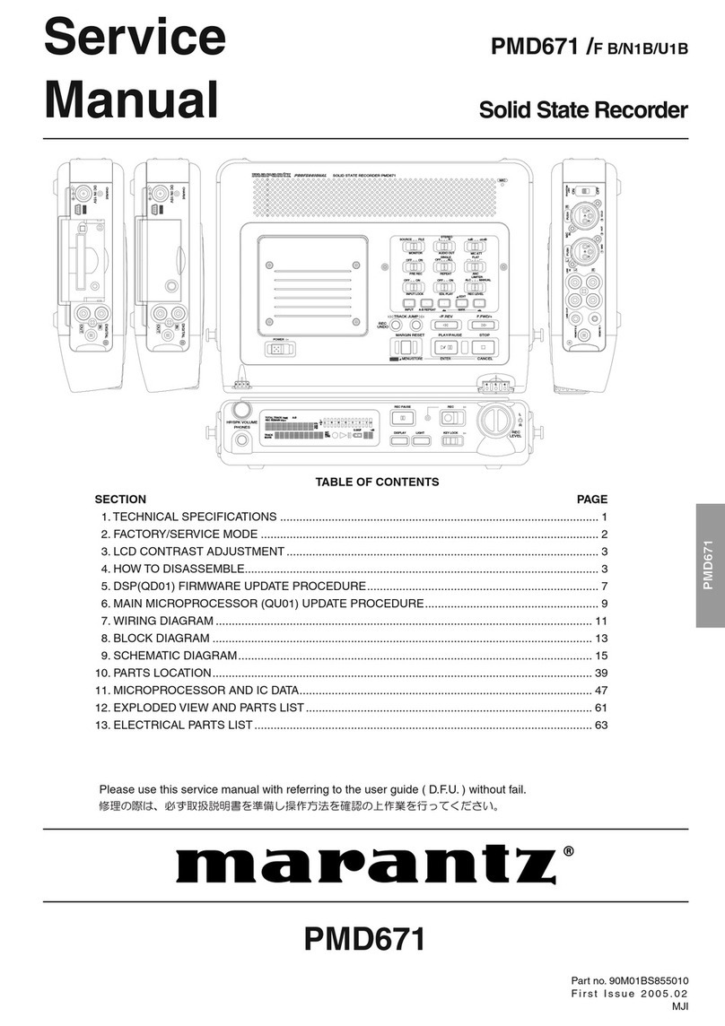
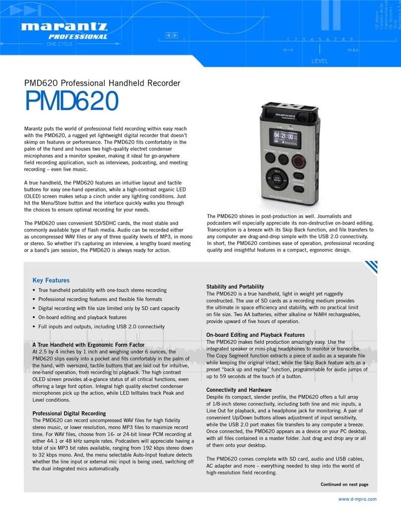
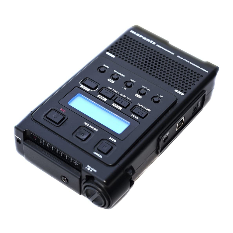
Marantz PMD680 User manual

1
SETTING UP
INTRODUCTION
Thank you for your purchase of the Marantz
Professional PMD680 PC Card Recorder. The PMD680 is
the next generation of porta le digital recorders that
ridge the gap etween real-time audio recording and
computers — while keeping the size and functionality of
our renowned porta le cassette and MiniDisc recorders.
The PMD680 has een designed as a field acquisition
tool. This means that the unit itself is designed to record
audio in a computer compati le file format. The audio
files are then meant to e transferred to a computer for
editing or transmission.
The recording medium of the PMD680, PCMCIA
compati le PC Cards, allows plug-and-play
compati ility with desktop and laptop computers. Flash
PC Cards are ased on flash memory technology that
features no moving parts and is not affected y
movement and temperature. Flash memory cards are
availa le through most computer and digital
photography products resellers. For a complete list of
approved cards for the PMD680, please refer to the
Marantz Professional we site at www.marantz.com.
The MP2 (MPEG1 layer2) file format that is supported
y the PMD680 is a worldwide standard for compressed
digital audio storage and transmission. Many play ack
and editing systems are availa le commercially and
through the Internet. For more information on MP2
ased play ack and editing systems, please consult your
dealer.
Also supported y the PMD680, PCM (Pulse Code
Modulation) is the most widely used format for coding
uncompressed digital audio. The PCM system is used
on CD players, DAT recorders, and on computer editing
programs that support Wave (.wav) files. Recording in
the PCM format will provide the most universally
accepted storage format ut comes with the limitation
that it uses a lot of memory very quickly.
USING THIS MANUAL
Please read these operating instructions carefully. We
recommend that you read the entire user guide efore
you connect or operate the unit.
After you have reviewed the contents this manual, we
suggest that you make all system connections efore you
attempt to operate the unit.
FOREWORD
This section must e read efore any connection is made
to the mains supply.
WARNINGS
Do not expose the equipment to rain or moisture.
Do not remove the cover from the equipment.
Do not push anything inside the equipment through
the ventilation holes.
COPYRIGHT
Recording and play ack of any material may require
consent. For further information refer to the following:
—Copyright Act 1956
—Dramatic and Musical Performers Act 1958
—Performers Protection Acts 1963 and 1972
—any su sequent statutory enactments and orders
PRECAUTIONS
The following precautions should e considered when
operating the equipment.
When setting the equipment ensure that :
– air is allowed to circulate freely around the equipment
– the equipment is on a vi ration free surface
– the equipment will not e exposed to interference from an
external source
– the equipment will not e exposed to excessive heat, cold,
moisture or dust
– the equipment will not e exposed to direct sunlight
– the equipment will not e exposed to electrostatic discharges
• In addition, never place heavy o jects on the equipment.
• If a foreign o ject or water does enter the equipment, contact
your nearest dealer or service center.
Features
• Monaural (1 track) audio recording and play ack
• Recording onto various types of approved PC Cards
- Please refer to the Marantz Professional we site at
www.marantz.com for the complete list of approved
cards
• Two different recording formats:
- Compressed recording using MPEG1 Layer2 (MP2)
- Uncompressed recording using 16- it/48kHz Pulse
Code Modulation (PCM)
• MS-DOS and Windows compati le file system
• Selecta le file types:
- Wave (.wav)
- Broadcast Wave (. wf)
- Raw MP2 (.mp2)
• Manual, manual with limiter, and automatic (ALC)
record level control
• An ANC (Am ient Noise Cancel) switch for
eliminating unwanted ackground noises
• Pre-Recording memory uffer that records 2 seconds
prior to when recording is started
• Portions of multiple recordings can e played ack in
sequence using the EDL (Edit Decision List) system
• Three different ways to power the unit:
- Included AC adaptor
- 8 Alkaline AA atteries
- Optional rechargea le Ni-Cad attery pack
• Built-in Time and Date generator marks each
recording
• Telephone jack for recording and play ack using
standard analog telephone lines
• Remote input for pausing and un-pausing during
recording or play ack

2
SETTING UP
How to Use this Manual
This manual is divided into the 7 sections descri ed
elow. To find out how to use a specific control, refer to
the section "Index of Parts, Controls, and Display" on
page 26.
SETTING UP
This section descri es how to set up the unit in
preparation for recording and play ack.
PRESET MENU
This section provides information a out the various
preset menu options.
GENERAL FUNCTIONS
This section provides information a out the functions
and operations that are common for recording and
play ack.
RECORDING
This section descri es the various input controls, record
settings, and the asic recording procedure.
PLAYBACK AND EDITING
This section descri es the asic play ack procedure and
options, and details the editing options avail le to
recorded tracks.
THE EDL
This section descri es the EDL (Edit Decision List)
system and how to configure and manipulate EDL
marks in a recording to create a custom play ack
sequence.
ADDITIONAL INFORMATION
This section includes detailed information a out error
handling, the PC Card recording system,
trou leshooting, specifications, and the "Index of Parts,
Controls, and Display", which allows you to look up
operations of specific controls.
Contents
SETTING UP
AC Adaptor and Batteries .................................................... 3
Power On/Off ......................................................................... 4
Setting the Date and Time .................................................... 4
Understanding PC Card ....................................................... 5
Capacity of Files and Card ................................................... 5
Connecting Microphones...................................................... 6
Connecting Analog Components ........................................ 6
Connecting Digital Components......................................... 7
Other Connections ................................................................. 7
PRESET MENU
Preset Items.............................................................................. 8
Recording Time....................................................................... 8
Preset Operation ..................................................................... 8
GENERAL FUNCTIONS
Low Battery Warning and Auto Power Off.................... 10
Display Selections ................................................................ 10
Display Backlight ................................................................. 11
Key (Button) Lock ................................................................ 11
RECORDING
Input Controls ....................................................................... 12
Record Settings ..................................................................... 13
Recording Operation ........................................................... 14
PLAYBACK and EDITING
Play ack ................................................................................. 15
Track Editing ......................................................................... 16
THE EDL
EDL Marking ......................................................................... 18
Searching for EDL Marks ................................................... 19
Editing EDL Marks .............................................................. 20
EDL Play ack ........................................................................ 21
ADDITIONAL INFORMATION
Error Messages ...................................................................... 23
File Structure ......................................................................... 23
Trou leshooting.................................................................... 24
Care and Maintenance......................................................... 24
Specifications ......................................................................... 25
Index of Parts, Controls, and Display .............................. 26

3
SETTING UP
AC Adaptor and Batteries
AC Adaptor
When recording for extended periods, or using this unit
in a fixed environment, it is recommended to supply
power to the unit via the included AC adaptor.
to AC outlet
Note
• It is recommended to only use the Marantz Professional
rand AC adaptor (model DA600) for use with the
PMD680.
Alkaline Batteries
The PMD680 can operate using 8 standard AA size
alkaline atteries.
First load the atteries into the attery holder and then
load the holder as shown in the following illustration.
Battery Replacement
When the attery alert indicator ( ) appears steadily
in the display, replace all atteries with new ones. For
the complete description of the attery alert indiactor,
please refer to page 10.
Fresh alkaline atteries will provide at least 2 hours of
continuous recording or play ack (speaker and display
acklight off).
Notes
• When recording, to avoid pro lems caused y loss of
attery power, it is recommended to always use new
alkaline atteries.
• Use only AA size atteries for replacement.
• Be sure to insert the atteries with correct polarity (as
illustrated on the attery holder).
• Remove the atteries if the unit will not e used for an
extended period of time.
• Battery life may vary depending on the conditions under
which the unit is operated (environmental temperature,
humidity, speaker usage, etc.).
• If atteries leak, dispose of them immediately. Avoid
touching the leaking material or letting it come into
contact with clothing, etc. Clean the attery compartment
thoroughly efore installing new atteries.
• For optimum life and accurate attery display, make sure
the attery (" at") preset is set to "al". See page 9 for more
information on the preset menu.
Ni-Cad Rechargeable Battery (optional)
An optional Ni-Cad attery (model RB1100) is availa le
for use with the PMD680.
Refer to the following illustration to load the attery.
Battery Replacement
When the attery alert indicator ( ) appears steadily
in the display, charge the attery or replace the
rechargea le attery with a fully charged one.
A fully charged attery will provide at least 1 hour and
45 minutes of recording or play ack time.
Charging Battery
The optional Ni-Cad attery is charged only when:
• The AC adaptor is connected
• The Ni-Cad attery is loaded correctly in the attery
compartment
• The CHARGE slide switch is set to ON
• The power to the unit is off
While charging, the CHARGE LED will link.
When the charge cycle is complete, the CHARGE LED
will stay steadily on.
Notes
• The attery will not charge when the power to the unit is on.
Charging Time
Approximately 3 hours.
Notes
• Make sure to fully charge the attery efore first use.
• Battery life may vary depending on the conditions under
which the unit is operated (environmental temperature,
humidity, speaker usage, etc.).
• It is recommended to only use the Marantz Professional
rand AC adaptor (model DA600) for use with the
PMD680.
• For optimum life and accurate attery display, make sure
the attery (" at") preset is set to "nc". See page 9 for more
information on the preset menu.
• When recording, to avoid pro lems caused y loss of
attery power, it is recommended to always use a fully
charged attery.
• Remove the attery if the unit will not e used for an
extended period of time.
• If the charge switch does not light when charging should
e taking place, remove and then restore power.
• The attery power should e completely used efore it is
re-charged ecause Ni-Cad type atteries have a memory
effect which will reduce the total power for the attery if it
is only partially used and re-charged.

4
SETTING UP
Power On/Off
Power On
Sliding the power switch to the right turns the power
on. If a correctly formatted card is in the slot, the
message elow will e displayed.
Note
• TOC stands for Ta le of Contents and it is a reference to
the eggining of the card that contains the information on
all the audio tracks on the card.
If the card in the slot has not een formatted to the
specifications of the PMD680, the Un-Format display
will appear as indiacted elow:
If there is no card in the slot, then the following message
will e displayed:
Power Off
Sliding the power switch to the right while the power in
on will turn the power off.
Note
• While the unit is recording or in the record-pause mode,
the power switch is disa led.
Setting the Date and Time
Before operating your PMD680, perform the following
operations to set the current date and time.
The current date and time are recorded automatically at
the eginning of each recording.
1 With the power off, slide POWER to the right
while holding down the DISPLAY (TIME/
DATE) utton.
The unit turns on and enters the date/time
setup mode.
2 Press 1˜4 or ¢˜¡ to set the month,
then press PLAY/PAUSE (3˜8) to enter.
3 Press 1˜4 or ¢˜¡ to set the day, then
press PLAY/PAUSE (3˜8) to enter.
4 Press 1˜4 or ¢˜¡ to set the year, then
press PLAY/PAUSE (3˜8) to enter.
5 Press 1˜4 or ¢˜¡ to set the hour, then
press PLAY/PAUSE (3˜8) to enter.
6 Press 1˜4 or ¢˜¡ to set the minute,
then press PLAY/PAUSE (3˜8) to enter.
7 To save the input time/date information, press
the DISPLAY (TIME/DATE) utton. The
seconds will start counting from 00 and the
unit will enter the stop mode.
8 To return to the date setting display (step #2),
press the PLAY/PAUSE (3˜8) instead of the
DISPLAY (TIME/DATE) utton.
Notes
• Pressing the STOP (7) utton at any time during the time/
date setting mode will cancel any changes and return the
unit to the stop mode.
• The time is always displayed in 24-hour time. So for
example, 23:59:59 is equivalent to 11:59:59 PM.
OVER
5
5
5
5
5
5
5
5
5
5
5
5

5
SETTING UP
Understanding PC Cards
The PMD680 records digital audio directly to PCMCIA
and ATA compata le PC Cards. The PC Card storage
system allows direct plug-and-play compati ility with
conputers equipped with a PC Card slot.
PC Cards come in a variety of shapes and sizes. The
PMD680 is compati le with all types as long as they are
PCMCIA compata le.
Even though any PCMCIA compati le PC Card can e
read y the PMD680, only certain types of cards can
sustain the record speeds required. Therefore, only
cards tested and approved y Marantz Professional
should e used with the PMD680.
The recommended card list for the PMD680 can e
found on the Marantz Professional we site at
www.marantz.com.
Inserting a Card
Push the PC Card into the PMD680 as follows.
Note
• Make sure the card is inserted with the correct side facing
up.
Ejecting a Card
Push the EJECT utton as indicated to eject the PC Card
from the PMD680.
Notes
• The EJECT utton is mechanical and ejects the PC Card
regardless of the unit’s power or operating status.
Do not press EJECT while recording (when the REC
indicator is lit). This may result in the loss of all data on
the PC Card.
• Also do not eject the card when the unit is checking the
card ("CHE card" display) or when the TOC is eing read
("toc" display).
PUSH
Formatting a PC Card
Before using a PC Card for the first time, perform the
following operations to format the PC Card so that it
can e used to record audio. This operation completely
erases any information stored on the card. Be sure to
ackup any important information efore formatting.
Note
You can also use this operation to completely erase a
previously used PC Card containing audio data you no longer
need.
Operation
1 Make sure the power is off.
2 Insert the PC Card to e formatted.
3 Slide the POWER switch to the right while
holding down the ERASE (FORMAT) utton.
4 The format message elow will e displayed.
5 After formatting the card and generating the
EDL file, the "done" message elow is
displayed for 3 seconds.
6 The unit then enters the stop mode
Notes
• Even if a PC Card was formatted in a Windows
compati le PC, formatting y the PMD680 is neccessary.
• After recording and erasing a card many times, it is
recommended to format the card so that new recording
can e stored in the optimum way.
• Do not eject the PC Card or turn this unit’s power off
while formatting is in progress.
Care of PC Cards
Please refer to the documentation included with your
PC card for proper care.
Capacity of Files and Card
Due to limitations in the MS-DOS compata le file
structure system, the maximum size of all the recorded
tracks on a card is 1,200MB (MegaBytes) or 1.2GB
(GigaBytes).
The maximum card size that can e read y the PMD680
is 2,150MB (MegaBytes) or 2.15GB (GigaBytes). Cards
larger than 2.15GB may not work correctly in the
PMD680.
OVER
OVER

6
SETTING UP
To output analog audio signals to another
audio component
Connect the LINE OUT (RCA) jack on the PMD680 to
the analog input on the destination component.
Note
• To connect the mono PMD680 LINE OUT to a stereo input,
a Y-adaptor ca le can e used.
To record from or output through a telephone
line
Connect the phone line to the TELEPHONE IN/OUT
jack as follows.
Notes
• Please e advised that connecting the PMD680 to a
telephone line is illegal in some countries.
• Telephone calls must e placed and received with the
connected phone.
Connecting Microphones
A dynamic or an externally powered condensor
microphone can e connected to the PMD680 via a 1/4"
or XLR connection.
Connect microphones as shown elow.
Notes
• Take care not to connect or disconnect microphones while
recording. This may result in unwanted sounds in the
recording.
Connecting Analog
Components
The following illustrations show you how to connect
analog audio components for recording or play ack.
To record from analog audio components
Connect the source component’s analog line output
jacks to the PMD680's LINE IN (RCA) jack.
Note
• To connect a stereo source to the mono PMD680 LINE IN,
a Y-adaptor ca le can e used.
MIC (1/4")
MIC (XLR)
or
MIXER, TAPE DECK, etc.
MIXER, etc.
LINE OUT
LINE IN
Phone
RJ-11 splitter
Wall jack

7
SETTING UP
Connecting Digital Components
The following illustrations show you how to connect
digital audio components.
To output digital audio signals to another audio
component
Connect the DIGITAL OUT (RCA) jack on the PMD680
to the digital input jack on the destination component.
Turn the output on y placing the switch (next to the
output jack) in the ON position.
Notes
• Digital audio is only output during normal play ack and
EDL play ack. Digital audio is not output during
recording even if the output is turned on.
• When the digital output is not used, make sure to keep the
DIGITAL OUT switch OFF to save attery life.
• Make sure the destination component accepts the SPDIF
(or IEC-958-II) type digital audio format.
• Make sure the destination componet accepts a sampling
frequency of 48kHz or contains a digital sample rate
converter.
Other Connections
Headphones
Connect headphones to the HEADPHONE output as
indicated elow. Both recording and play ack can e
monitored through connected headphones.
Notes
• Use the HP/SPK VOLUME kno to control the volume of
the headphone.
• The sound from the internal speaker is muted
automatically when headphones are connected.
DAT, etc.
DIGITAL IN
Contact closure
switch
Open Close
Recording Pause recording Resume recording
Playback Pause playback Resume playback
Polarity of the REMOTE jack
Remote Control
Available Functions
The remote Pauses or Un-Pauses the unit during
play ack and recording.
REMOTE

PRESET MENU
8
Preset Items
The preset menu of the PMD680 allows many features
and functions of the unit to e customized for
individual requirements.
The following items can e accessed in the preset menu:
• Bitrates assigned to the SP/MP/LP switch
• Sound detection level of the silent skip function
• Detection time of the silent skip function
• Battery type used
• File format of the recorded tracks
• ID1
• ID2
• ID3
Notes 1)
• No two itrates can have the same value.
• The SP setting must e greater than the MP.
• The MP setting must e greater than the LP setting.
Note 2)
Please refer to the following section.
Recording Time
The amount of memory required per hour of recording
is as follows.
Preset Operation
1. While power is off, press and hold the AUTO
MARK (PRESET) utton and then slide the
power switch to the right.
2. The unit should enter the preset setting mode
and "Preset" should e indicated in the display.
3. The unit will then automatically display
(flashing) the first preset -- itrate for the SP
record mode.
4. Use 1˜4 and ¢˜¡ uttons select
which preset item you would like to change.
The order of the preset menu items is the same
as indicated on a preset chart on this page.
5. Use the PLAY/PAUSE utton to alternate
etween changing the preset item and the
availa le options for the currently displayed
preset (the preset item options will flash).
6. Use 1˜4 and ¢˜¡ uttons to then
select which option you would like for the
current preset item.
7. When finished making a change to a preset
item, press the PLAY/PAUSE utton to select
another preset item to change (preset item will
flash).
8. When finished setting all the presets, press the
AUTO MARK (PRESET) utton to save all the
changes and exit the preset menu mode.
9. If you do not want to save the changes made to
the preset menu, press the STOP utton to exit
without saving the changes.
10. After exiting the preset menu mode, the unit
will return to normal operation in the stop
mode.
Preset
Display
Available Options Default
Setting
Bit rate of SP
1)
br
7
68, 192, 128, 64 kbps
2)
128 kbps
Bit rate of MP
1)
br
192, 128, 64, 48 kbps
2)
64 kbps
Bit rate of LP
1)
br
128, 64, 48,32 kbps
2)
48 kbps
Sound level for silent skip
SL
-50dB to -10dB, 5dB step -40 dB
Silent time for silent skip
St
1 to 5 second
3 seconds
Battery type
bat
Alkaline, Ni-Cad Alkaline
File format For Wave (.wav), MP2 (.mp2), MP2
Broadcast Wave (.bwf)
ID1,2,3
Id1 000000 to 999999 000000
Id2
Id3
AUTO MARK
PRESET
1/ 4¢/ ¡
STOP (7)
PLAY / PAUSE
(6)
Bit Rate (kbps) MB/Hour
32 16 MB
48 25 MB
64 33 MB
128 67 MB
192 100 MB
768 (PCM) 400 MB

PRESET MENU
9
OVER
OVER
OVER
5
5
5
5
5
5
5
5
5
5
5
5
5
5
5
5
5
5
5
5
5
5
5
5
5
5
5
5
5
5
5
5
5
5
5
5
ID Number Presets
The ID num ers are saved in the 'Extension Chunk' of
the Broadcast WAVE (BWF) file format. The IDs are
defined as follows:
ID1 :Description
ID2 :Originator
ID3 :Originator Reference
Example:
If the IDs are used in a roadcast station situation:
• ID1 could e used for the ID of the roadcasting
station
• ID2 could e used for the department code
• ID3 could e used for the adge num er of the
reporter
ID Number Setting Operation
• The PLAY/PAUSE utton will cycle through each
digit of the selected ID#.
• The 1 /4 and ¢ / ¡ uttons will increase or
decrease the digit that is flashing.
Example: Changing the battery type preset
Display for Alkaline
battery.
1 /4, ¢ / ¡
Display for Ni-Cad battery.
Example: Changing the file format preset
Display for Wave
(.wav) file format.
1 /4, ¢ / ¡
Display for MP2
(.mp2) file format.
1 /4, ¢ / ¡
Display for Brodcast Wave (.bwf) file format.
OVER
OVER
5
5
5
5
5
5
5
5
5
5
5
5
5
5
5
5

GENERAL FUNCTION
10
-dB 50 40 24 6 2 0∞
TRACK TIME
12
OVER
5
5
5
5
5
5
5
5
Display Selections
Changing the Displayed Information
Pressing the DISPLAY (TIME/DATE) utton will
change the displayed information as follows.
During Stop Mode
qTotal Track # Total Track Time
wTotal Track # Total Remain Time
(time availa le for recording
at the selected it rate)
eCurrent Time
Note
• The time is always displayed in 24-hour time. So for
example, 23:59:59 is equivalent to 11:59:59 PM.
rCurrent Date
Low Battery Warning and
Auto Power Off
The PMD680 has uilt-in power management and
emergency shut-down system when Alkaline atteries
or the optional Ni-Cad attery is used.
To make sure this system operates correctly, make sure
the attery preset (" at") in the preset menu is set
correctly. Please refer to page 9 for more information
on how to set the presets.
1st Warning
When the remaining attery time starts running low, a
1st warning will appear. The 1st warning is when the
low attery indicator appears in the display as follows.
2nd Warning
When the remaining attery time ecomes extremely
low, the 2nd warning will appear. The 2nd warning is
when the attery indicator egins to flash together with
the REC LED (when in the recording mode) as follows.
Shut-Down
If the unit continues to operate after the 2nd warning
appears, the unit will enter an automatic shut-down
procedure efore all power is lost. Recording or
play ack will stop and the unit will automatically
power itself off.
-dB 50 40 24 6 2 0∞
TRACK TIME
12
OVER
-dB 50 40 24 6 2 0∞
TRACK TOTAL TIME
12
OVER
-dB 50 40 24 6 2 0∞
TRACK REMAIN TIME
12
OVER
-dB 50 40 24 6 2 0∞ 12
OVER
-dB 50 40 24 6 2 0∞ 12
OVER

GENERAL FUNCTION
11
During Playback and Play-Pause
qCurrent Track # Time elapsed on current
playing track
wCurrent Track # Remaining time of current
playing track
eCurrent Track # Accumulated time elapsed
(Total time of tracks previous
to the current track + time elapsed
on current playing track)
rCurrent Track # Total play ack remain time
(Total time of tracks after the
current track + remain time
of current playing track)
tRecorded Bit Rate Time when the current track
of the Current Track was recorded
Note
• The time is always displayed in 24-hour time. So for
example, 13:21:03 is equivalent to 1:21:13 PM.
yRecorded Bit Rate Date when the current track
of the Current Track was recorded
-dB 50 40 24 6 2 0∞
TRACK TIME
12
OVER
-dB 50 40 24 6 2 0∞
TRACK REMAIN TIME
12
OVER
-dB 50 40 24 6 2 0∞
TRACK TOTAL TIME
12
OVER
-dB 50 40 24 6 2 0∞
TRACK TOTAL REMAIN TIME
12
OVER
-dB 50 40 24 6 2 0∞
RECORDED
TIME
12
OVER
-dB 50 40 24 6 2 0∞
RECORDED
12
OVER
During Recording and Record-Pause
qCurrent Track # Recording elapsed time on
current track
wCurrent Track # Remaining recording time
(Time availa le for recording)
eCurrent Track # Accumulated recording time
elapsed
(Total time of tracks previous
to the current track + recording
time elapsed on the current track)
Display Backlight
To Illuminate the Display:
• Press the LIGHT utton:
The display acklight will turn on for 3 seconds and
then turn off.
• Press and hold the LIGHT utton for more than 1
second:
The display acklight will stay on until it is turned off
y pressing the LIGHT utton or if the power is
turned off.
Key (Button) Lock
The KEY LOCK switch sets the unit in the mode at the
time the switch was set. This locking function can
prevent accidental changes in a set mode or lock the
unit in recording or play ack.
While the Key Lock is on, the only switches and
functions availa le are as follows:
• LIGHT
• POWER (except during recording)
• All the top panel slide switches except: PRE REC and
REC MODE
If a locked utton is pressed, the following message will
e displayed.
REC
SP
-dB 50 40 24 6 2 0∞
TRACK TIME
12
OVER
REC
SP
-dB 50 40 24 6 2 0∞
TRACK REMAIN TIME
12
OVER
REC
SP
-dB 50 40 24 6 2 0∞
TRACK TOTAL TIME
12
OVER
-dB 50 40 24 6 2 0∞
TRACK
12
OVER

12
RECORDING
Input Controls
INPUT Selection
The PMD680 can record from a variety of inputs:
• XLR micorphone connection
• 1/4" microphone connection
• Internal microphone
• Line level source
• Telephone line
The INPUT switch offers selection of a telephone (TEL),
microphone (MIC), or line level (LINE) input.
Note
• The MIC switch a ove the INPUT switch is only active
when the INPUT switch is set to the middle (MIC)
position.
The chart elow indiactes which input is effective for
each of the MIC switch positions.
MIC ATTEN (Attenuation)
The MIC ATTEN switch adjusts the ase input level for
all the external microphone inputs only, i.e. the XLR
and 1/4" microphone inputs.
Adjusting the microphone attenuation allows
microphones with higher sensitivity to e recorded and
controlled the same way as microphones with lower
sensitivity.
ANC (Ambient Noise Cancel)
The ANC (Am ient Noise Cancel) switch microphone
inputs ut does not affect the line input and telephone
input.
This ANC feature allows the recorder to filter out
unwanted ackgraund noise. The availa le settings are
as follows.
• Band-pass ( ) : Cuts low frequency (150Hz and
lower, ex : wind noise, proximity effect) and high
frequency (3KHz and higher)
• Flat : No filtering
• Low-cut ( ) : Cuts low frequency (150Hz and lower,
ex : wind noise, proximity effect)
REC LEVEL Control
The PMD680 offers three ways in which to control the
recording level: manual (MANUAL), manual with a
limiter (LIMITER), and automatic (ALC).
• MANUAL: The recording level is controlled y the
REC LEVEL kno .
• LIMITER: The recording level is controlled y the
REC LEVEL kno ut a limiting circuit in the PMD680
will not allow the input signal to overload (go past
the -12dB mark on the level meter). The recover time
is short so that the set record level is maintained as
much as possi le.
The REC LED will dim when the Limiter is heavily
limiting the input signal.
• ALC (Automatic record Level Control): The recording
level in this mode is controlled exclusively y the
PMD680 and the REC LEVEL kno is disa led. The
recover time of the system is long so that the
recording level does not constantly fluctuate.
Setting the Record Level
• The optimum recording level is where the peak of the
input sound just arely flickers past the -12dB point
(highlighted in lack in the display).
• The recording level should never reach the overload
point in the level meter (OVER sym ol highlighted in
lack). Reaching that point will result in digital noise
which is very uncomforta le for the ear.
Input Controls Summary
MIC
ON 1
2/INT SP LP
OFF
LOCKOFF
SPEAKER
ALC
LIMITER
REC LEVEL
KEY LOCK
MANUAL
TEL LINE
INPUT
PRE REC
MP
REC MODE
MIC ATTEN
FLAT
ANC
-30dB
OFF ON
-15dB
0dB
ON 1
SP LP
OFF
LOCKOFF
SPEAKER
ALC
LIMITER
REC LEVEL
KEY LOCK
MANUAL
TEL LINE
PRE REC
MP
REC MODE
FLAT
ANC
-30dB
OFF ON
-15dB
0dB
MIC
2/INT
INPUT
MIC ATTEN
ON 1
SP LP
OFF
LOCKOFF
SPEAKER
ALC
LIMITER
REC LEVEL
KEY LOCK
MANUAL
TEL LINE
PRE REC
MP
REC MODE
FLAT
ANC
-30dB
OFF ON
-15dB
0dB
MIC
2/INT
INPUT
MIC ATTEN
MIC ATTEN ANC REC LEVEL
Not effective Not effective Effective
Effective Effective Effective
Not effective Effective Effective
Not effective Not effective Effective
Input
Telephone Input
XLR microphone
connector input
1/4" microphone
connector input
Internal
microphone Input
Line Input
MIC
Switch
MIC switch
position
1 2 / INT MIC
1/4" connector
Inserted
XLR microphone
connector input 1/4" microphone
connector input
Not inserted
Internal Microphone
Input

13
RECORDING
Record Settings
REC MODE
Three programma le record modes are availa le for
each track that is recorded. See the Preset Menu section
for information on how to change the value of each of
the record modes.
The three availa le modes are as follows.
• LP (Long Play mode): The setting with the longest
recording time. The “LP” icon will e displayed when
in the record-pause or record modes.
• MP (Medium Play Mode): This setting offers higher
sound quality than the LP mode ut takes up more
memory space. There will no icon displayed during
the record-pause and record modes.
• SP (Short Play mode): The setting with the highest
sound quality ut the shortest record time. The “SP”
icon will e displayed during the record-pause and
record modes.
PRE REC
The 2-second pre-record feature is active when the PRE
REC switch is set to the ON position.
When pre-record is active, the unit will record 2 seconds
of audio efore the record utton is pressed to start
recording. The enefit of the pre-record function is that
it can prevent missed or delayed starts of a recording.
Notes
• For the pre-record function to operate correctly, the
PMD680 must e in the record-pause mode for at least 2
seconds. If the unit is in record-pause for less than 2
seconds, then the pre-record time will e shorter than 2
seconds.
• When recording is started with the pre-record function
active, the elapsed recording time in the display will start
at the 2 seconds mark.
• Pre-record is automatically activated when the Silent Skip
feature is on.
SILENT SKIP
The SILENT SKIP utton activates the silent skip mode
and the “S.SKIP” icon will e displayed.
The silent skip system operates during the record mode
only and is ased on the parameters set in the preset
menu. Please refer to the Preset Menu section on page 8
for information on setting the operational parameters of
the silent skip system.
When active during recording, the silent skip system
will continually look for the preset sound level, for the
preset amount of time. If the preset sound level is
sensed for the preset time, the unit will enter the record-
pause mode.
The silent skip system will then stay in the record-pause
mode until a signal of approximately -30dB is input.
The unit will then re-enter the record mode and will
continue to record until the preset parameters of the
silent skip system are meet again.
Notes
• When first going into the record-pause mode from stop,
recording must e started manually with the REC/MARK
utton. After recording is started, the silent skip system
will control the recording.
• If the silent skip system pauses a recording, recording can
e re-started manually y pressing the REC/MARK or
PLAY/PAUSE uttons.
• The pre-record function is always active while the silent
skip function is turned on. This is done to prevent audio
from eing cut-off when the system starts and stops.
AUTO MARK
The AUTO MARK utton activates the auto marking
system and the “A.MARK” icon will e displayed.
When the auto mark feature is active, every time a
recording is paused, manually or y the Silent Skip
system, an EDL mark is placed at that point in the track.
Please refer to the section titled "The EDL" on page 18
for information on the meaning and uses of the EDL
marks.
Notes
• Auto mark can e switched on or off in any mode.
• An EDL mark is automatically placed at the eginning of
each track, regardless if the auto mark function is on or
off.
• Marks are automatically placed in the normal record mode
and also in the silent skip record mode.
• The maximum num ers of EDL marks on a card is 255. If
the card reaches 255 marks, the auto mark function will
automatically turn off and the AUTO MARK utton will
not allow the function to e re-activated.
• If the maximum num er of EDL marks (255) is reached,
“FULL -P 255” will e indicated on the display for 3
seconds.
• If the maximum num er of EDL marks (255) is reached,
individual EDL marks or all the EDL marks can e erased.
Please refer to the Editing EDL Marks section on page 20
for information a out erasing EDL marks.
ON 1
SP LP
OFF
LOCKOFF
SPEAKER
ALC
LIMITER
REC LEVEL
KEY LOCK
MANUAL
TEL LINE
PRE REC
MP
REC MODE
FLAT
ANC
-30dB
OFF ON
-15dB
0dB
MIC
2/INT
INPUT
MIC ATTEN
ON 1
SP LP
OFF
LOCKOFF
SPEAKER
ALC
LIMITER
REC LEVEL
KEY LOCK
MANUAL
TEL LINE
PRE REC
MP
REC MODE
FLAT
ANC
-30dB
OFF ON
-15dB
0dB
MIC
2/INT
INPUT
MIC ATTEN
REPEAT RENUMBER ERASE SILENT SKIP AUTO MARK
FORMAT PRESET
REPEAT RENUMBER ERASE SILENT SKIP AUTO MARK
FORMAT PRESET

14
RECORDING
Recording Operation
Basic Procedure
1. Make sure all input selection and record
settings are made correctly.
2. Press the RECORD/MARK utton to enter the
Record-Pause mode. The input signal will now
appear in the level meter of the display and the
REC LED and REC indicator in the display will
flash.
3. If the REC LEVEL switch is set to MANUAL or
LIMITER, the REC LEVEL kno will e active
and allow you make adjustments to the
recording level ased on the input source.
Refer to page 12 for information on setting the
recording level.
4. When ready to record, press the RECORD/
MARK utton to start recording. The REC
LED and REC indicator in the display will stay
steadily on and the current track num er will
quickly alternate with the next EDL mark
num er, showing that an EDL mark was
placed at the eginning of the track.
Note
• Pressing the REC/MARK utton during recording will
add an EDL mark at the point that the utton was pressed.
record settings
STOP
REC/MARK
REC LED
5. To stop recording ut then continue to record
to the current track, recording must e paused
and not stopped. Press the PLAY/PAUSE
utton to enter the record-pause mode and
then press REC/MARK to resume recording.
6. When ready to stop recording and complete
the current track, press the STOP utton. The
TOC will e updated and the unit will enter
the stop mode.
Notes
• All record settings can e changed during recording
except the REC MODE. If the REC MODE is changed
during recording, the new setting takes effect for the next
track.
• If the Auto Mark feature is active during recording, every
time a track is paused an EDL mark is added.
• The REC LED will dim when the Limiter is heavily
limiting the input signal.
• The minimum length of a track is 0.5 seconds. A track of
less than 0.5 seconds will not e recorded on the card.
Full Cards
The following message will appear if the PC Card is
filled during recording or if attempting to start
recording with a full card.
In order to re-use a full card, tracks need to e erased or
the card needs to e re-formatted (erases all tracks).
Maximum Number of Tracks
Each PC Card can hold a maximum of 255 tracks. When
attempting to start recording when the maximum
num er of tracks is reached, the following message will
e displayed.
In order to continue to use a full card, tracks need to e
erased or the card needs to e re-formatted (erases all
tracks).
rec-pause
recording
REC
REC
SP LP
-dB 50 40 24 6 2 0
∞
TRACK TIME
12
OVER
5
5
5
5
5
5
5
5
5
5
5
5
5
5
5
5
5
5
5
5
5
5
REC
SP LP
-dB 50 40 24 6 2 0
∞
TRACK TIME
12
OVER
REC

15
PLAYBACK and EDITING
Playback
The standard play ack mode will play all the tracks on
a card in order. Alternative play ack options are the
EDL play ack mode, where the EDL marks in the tracks
control play ack, and the Repeat play ack mode where
either a single track is continually repeated or all the
tracks on a card are continually repeated.
The played ack audio signal is simultaneously output
to the HEADPHONE jack, LINE OUT, TELEPHONE
IN/OUT, DIGITAL OUT (if turned on), and speaker (if
turned on and no headphones are connected). The HP/
SPK VOLUME kno a ove the HEADPHONE jack
controls the output volume through the headphones
and speaker. All other outputs are a fixed level.
Note
• Even when the SPEAKER switch is ON, the speaker will
not output sound if headphones are connected.
Basic Procedure
1. From the stop mode, press the PLAY/PAUSE
utton to start play ack from the first track on
the card.
2. Play ack can e paused at any point y
pressing the PLAY/PAUSE utton. Play ack
is resumed y pressing the PLAY/PAUSE
utton.
3. Press the DISPLAY (TIME/DATE) utton to
alternate etween the various track
information display options. Refer to the
Display Selections section on page for more
information.
4. Play ack will continue until the all the tracks
on the card have een played or the STOP
utton is pressed to stop play ack.
1/ 4¢/ ¡
EDL PLAY
PLAY / PAUSE
(6)
STOP (7)
DISPLAY
SPEAKER
Starting Playback from a Selected
Track
1. From the stop mode, press the 1/4 or
¢/¡ utton until the desired play ack
track is indicated in the display.
2. Press the PLAY/PAUSE utton to start
play ack.
3. Play ack can e paused at any point y
pressing the PLAY/PAUSE utton. Play ack
is resumed y pressing the PLAY/PAUSE
utton.
4. Press the DISPLAY (TIME/DATE) utton to
alternate etween the various track
information display options. Refer to the
Display Selections section on page 10 for more
information.
5. Play ack will continue until the all the
remaining tracks on the card have een played
or the STOP utton is pressed to stop play ack.
Reverse and Forward Search
During play ack, press and hold the 1/4 or ¢/
¡ utton to perform an audi le search (4 times normal
speed) in the reverse or forward direction. Release the
1/4 or ¢/¡ utton to return to the normal
play ack speed.
Notes
• Reverse and forward searching will continue to the next or
previous track if held down past the eginning or the end
of a track.
• If Repeat or Repeat 1 is on, the searching will follow the
track order of the Repeat mode.
• These functions are not availa le during EDL play ack
and EDL repeat play ack modes.
Fast Reverse and Forward Search
For very large tracks, the normal reverse and forward
search speeds are too slow if certain points later in the
track need to e reached. Therefore, a 30 and 250 times
normal speed search is possi le.
During play ack, press the PLAY/PAUSE utton to
enter the play-pause mode in the desired track you want
to search. Then press and hold the 1/4 or ¢/¡
utton to start fast search in the reverse or forward
direction. The search speed will e 30 times normal for
3 seconds and then ecome 250 times normal for the rest
of the time the utton is held. Release the 1/4 or
¢/¡ utton to return to the play-pause mode.
Notes
• There is no sound output in either of the fast search
speeds.
• Reverse and forward searching will continue to the next or
previous track if held down past the egging or the end of
a track.
• If Repeat or Repeat 1 is on, the searching will follow the
track order of the Repeat mode.
• These functions are not availa le during EDL play ack
and EDL repeat play ack modes.

16
PLAYBACK and EDITING
Selecting Tracks
In the stop, play, or play-pause modes, tracks previous
or next are selected y pressing the 1/4 and ¢/
¡ uttons, corresponding the desired direction.
If the 1/4 utton is pressed while playing ack a
track or when paused at some point in a track, the
eginning of the current track is selected. Quick
su sequent presses of the 1/4 utton will then
select previous tracks.
Note
• Erased tracks num ers are skipped when selecting tracks
unless the Renum er function is performed. Please refer
to page 17 for more information on the Renum er
function.
• These functions are not availa le during EDL play ack
and EDL repeat play ack modes.
Repeat Play
The PMD680 can e set to repeatedly play ack a single
track or all the tracks on a card.
To enter the single track repeat mode, press the REPAT
utton o that the "REPEAT 1" is indicated in the display
as shown elow.
To enter the all track repeat mode, press the REPEAT
utton so that "REPEAT" is indicated in the display as
shown elow.
-dB 50 40 24 6 2 0
∞
TRACK TIME
12
OVER
REPEAT 1
-dB 50 40 24 6 2 0
∞
TRACK TIME
12
OVER
REPEAT 1
Track Editing
The PMD680 allows only two ways to directly
manipulate the recorded tracks on a card, Erase and
Renum er.
Erasing a track will permanently delete a recorded track
from a card. The track num er of the deleted file is
eliminated ut a higher num er track does not take its
place. The deleted track num er remains gone until the
Renum er function is performed.
Note
• The next recorded track is always the last track on the
card. Therefore, if a deleted track is the last track on a
card or a deleted track is the last track on the card and
other tracks directly previous have een deleted, then the
next recorded track num er will e a num er of a track
that has een deleted.
The Renum er function will re-order all the tracks on a
card in a sequential order starting from num er 1. For
example, if a card has three tracks num ered 2, 4, and 6,
the Renum er function will change the track num ers to
1, 2, and 3. So the old track 2 ecame track 1, the old
track 4 ecame track 2, and the old track 6 ecame track
3.
PLAY / PAUSE
(6)
REPEAT

17
PLAYBACK and EDITING
Track Erase
1. From the stop mode, use the 1/4 and
¢/¡ uttons to select the track that is to e
deleted.
2. Press the ERASE (FORMAT) utton. The
"Erase" message will flash in the display as
follows.
3. Press the ERASE utton again to confirm the
track erase. The "Erase" message will stay
steadily on in the display as follows to indicate
that the Erase function is executing.
4. When the Erase function is finished, the "done"
message is indicated in the display for 3
seconds as follows.
5. The unit will then return to the stop mode.
Notes
• The STOP utton can e used to cancel the Erase function
efore it is confirmed.
• Use the Format function to erase all the tracks on a card.
REPEAT RENUMBER ERASE SILENT SKIP AUTO MARK
FORMAT PRESET
TRACK
OVER
5
5
5
5
5
5
5
5
5
5
5
5
5
5
5
5
5
5
5
5
5
5
5
5
TRACK
TRACK
Renumber
1. From the stop mode, press the RENUMBER
utton. The "re no" message will flash in the
display as follows:
2. Press the RENUMBER utton again to confirm
the track renum ering. The "re no" message
will stay steadily on in the display as follows to
indicate that the Renum er function is
executing.
3. When the Renum er function is finished, the
"re done" message is indicated in the display
for 3 seconds as follows.
4. The unit will then return to the stop mode.
Note
• The STOP utton can e used to cancel the Renum er
function efore it is confirmed.
OVER
5
5
5
5
5
5
5
5
5
5
5
5
REPEAT RENUMBER ERASE SILENT SKIP AUTO MARK
FORMAT PRESET

THE EDL
18
EDL Marking
The EDL marking and play ack system of the PMD680
allows either a custom play ack sequence to e
programmed or the audio etween two specific points
in the card to e repeatedly played ack.
For the custom play ack sequence, the process is
completely linear, which means that the order of the
programmed sequence must correspond to the order of
the audio tracks on the card. So asically the EDL
system allows portions of the audio data stored on the
card to e skipped.
EDL marks are placed on the card in various ways.
During recording, marks are placed:
• At the eginning of each new track
• When the REC/MARK utton is pressed
• When the AUTO MARK function is active and the
PMD680 is placed in the record-pause mode manually
or via the SILENT SKIP function
During play ack or play-pause, marks are placed:
• When the REC/MARK utton is pressed
Each mark has the possi ility to e defined as one of
four types:
Play Mark ("P") – The asic indication for an EDL mark
and, during EDL play ack, a marker to indicate that the
audio after the mark is to e played until the next EDL
mark.
Skip Mark ("S") – During EDL play ack, a marker to
indicate that the audio after the mark is to e skipped
until the next EDL mark.
A Point Mark ("a") – The start point for a repeating loop.
B Point Mark ("b") – The end point for a repeating loop.
All new EDL marks are initially placed as Play marks.
After recording or play ack is complete, the definition
of all the EDL marks on the card can e changed. Refer
to page 20 in this section for more information on how
to change a mark type.
Every time an EDL mark is placed on a card, the total
quantity of the EDL marks on the card is displayed for
one second in the track num er display area (see
example elow). This is meant to provide a reference of
what num er EDL mark is at that specific location and
an indication of the remaining EDL marks on the card.
The maximum num er of EDL marks per card is 255.
When the maximum num er of EDL marks has een
placed, the following message will appear in the
display.
In order to place EDL marks after the a ove message is
displayed, either individual or all the EDL marks on the
card need to e erased. Refer to page 20 in this section
for more information on performing the EDL mark erase
functions.
Notes
• The EDL marks are stored as a separate EDL file on the
card that is only reada le y the PMD680. Do not attempt
to edit or delete this file on a PC.
• If all availa le EDL marks have een placed, the Auto
Mark function will automatically e turned off and will
not e availa le again until there are availa le EDL marks
on the card.
• There can e only one A and one B point on each card. If
an A or B point exists on a card and a new A or B point is
marked, the new A or B point replaces the old A or B point
and the old A or B point ecomes a P point.
When a mark is placed, the total
quantity of mark is displayed
(total mark quantity = 192)
After one second, the display
returns to the track num er
display
(track num er = 124)
-dB 50 40 24 6 2 0∞
TIME
12
OVER
-dB 50 40 24 6 2 0∞
TRACK TIME
12
OVER
MARK SELECT
ERASE
REPEAT
JUMP TO MARK
EDL PLAY
TOTAL MARK
1/ 4¢/ ¡
STOP (7)REC / MARK
PLAY / PAUSE
(6)

THE EDL
19
Auto Mark
The Auto Mark function automatically places an EDL
mark on the card when the PMD680 enters the record-
pause mode from the record mode. The record-pause
mode is entered either manually via the PLAY/PAUSE
utton or in an automated way via the Silent Skip
system.
The Auto Mark function can e turned on and off at any
time. When Auto Mark is on, the "A.MARK" icon in the
display will light as follows.
Please refer to the Record Settings section on page 13 for
more information on the Auto Mark function.
Searching for EDL Marks
From the stop mode, the EDL marks on the card can e
searched for in either the forward or reverse direction.
Forward EDL Mark Search
EDL marks can e searched for in the forward direction
y holding down the JUMP TO MARK utton and
pressing the ¢/¡ utton. Every time the ¢/¡
utton is pressed, the PMD680 will search for the next
mark on the card. If forward search is performed while
at the last EDL mark on the card, the PMD680 will start
searching from the eginning of the card (EDL mark 1).
Reverse EDL Mark Search
EDL marks can searched for in the reverse direction y
holding down the JUMP TO MARK utton and pressing
the 1/4 utton. Every time the 1/4 utton is
pressed, the PMD680 will search for the previous mark
on the card. If previous search is performed while at
the first EDL mark on the card, the PMD680 will start
searching from the end of the card (last EDL mark).
REC
-dB 50 40 24 6 2 0∞
A.MARK
TRACK TIME
12
OVER
-dB 50 40 24 6 2 0∞
TIME
12
OVER
-dB 50 40 24 6 2 0∞
TRACK TIME
12
OVER
When a mark is located, the mark
num er accessed is displayed
(mark num er = 132)
After one second, the track
num er of where the mark was
placed is displayed
(track num er = 121)
Displaying the Total Number Of EDL Marks
While in the stop mode, the total num er of EDL marks
on the card can e displayed y holding down the
TOTAL MARK utton and then pressing the REC/
MARK utton. The total num er of EDL marks on the
card will then e displayed for 3 seconds as indicated
elow.
Display of Located EDL Marks
When an EDL mark is located, the num er of that
particular EDL mark is displayed for one second in the
track mark display area. Then the track num er where
the mark is located is displayed as the example elow
indicates.

THE EDL
20
Editing EDL Marks
After all the EDL marks are placed in the audio tracks of
a card, they can e edited y changing the mark types,
erasing specific marks, or erasing all the marks.
Changing a Mark Type
Locate the EDL mark to e changed y using the mark
search functions. When the desired EDL mark is
located, press the MARK SELECT utton to display the
current mark type. Each su sequent press of the MARK
SELECT utton will then change the mark type in the
following order.
-dB 50 40 24 6 2 0∞ 12
OVER
-dB 50 40 24 6 2 0∞ 12
OVER
-dB 50 40 24 6 2 0∞ 12
OVER
-dB 50 40 24 6 2 0∞ 12
OVER
P : Play
S : Skip
-a : Repeat Point A
-b : Repeat Point B
When the desired mark type is displayed, press the
PLAY/PAUSE utton to save the mark type. If you
decide not to change the mark, press the STOP utton to
cancel the mark changing operation.
Notes
• The mark type can also e automatically saved y
searching for the next or previous mark on the card.
• There can e only one A and one B point on each card. If
an A or B point exists on a card and a new A or B point is
marked, the new A or B point replaces the old A or B point
and the old A or B point ecomes a P point.
Erasing an EDL Mark
Locate the EDL mark to e erased y using the mark
search functions. When the desired EDL mark is
located, press the ERASE utton so that the display
flashes the mark type of the selected mark followed y
the "Erase" message. Press the ERASE utton again to
confirm the Erase function (or press the STOP utton to
cancel). When the erase operation is complete, the
"done" message will e displayed and then the unit will
return to the point where the mark was in the pause
mode.
The complete procedure is displayed as follows.
REPEAT RENUMBER ERASE SILENT SKIP AUTO MARK
FORMAT PRESET
OVER
-dB 50 40 24 6 2 0∞
TRACK
12
OVER
5
5
5
5
5
5
5
5
5
5
5
5
5
5
5
5
Waiting for confirmation.
Press the ERASE button to confirm.
Press the STOP button to cancel.
Erase operation executing.
Erase complete.
The PMD680 returns to the location of the erased mark.
Note
• Erasing an EDL mark will automatically renum er all the
EDL marks on the card. The result is similar to the track
Renum er function that is descri ed on page 16 in the
Track Editing section.
Other manuals for PMD680
2
Table of contents
Other Marantz Voice Recorder manuals

Marantz
Marantz PMD-706 User manual

Marantz
Marantz Professional PMD661 User manual

Marantz
Marantz PMD570 User manual

Marantz
Marantz PMD620 User manual

Marantz
Marantz PMD660/F User manual

Marantz
Marantz PMD620 User manual

Marantz
Marantz PMD671 User manual

Marantz
Marantz PMD650/N1B User manual

Marantz
Marantz PMD620MKII User manual

Marantz
Marantz PMD660 User manual