Margaroli Home 542/TS User manual
542/TS
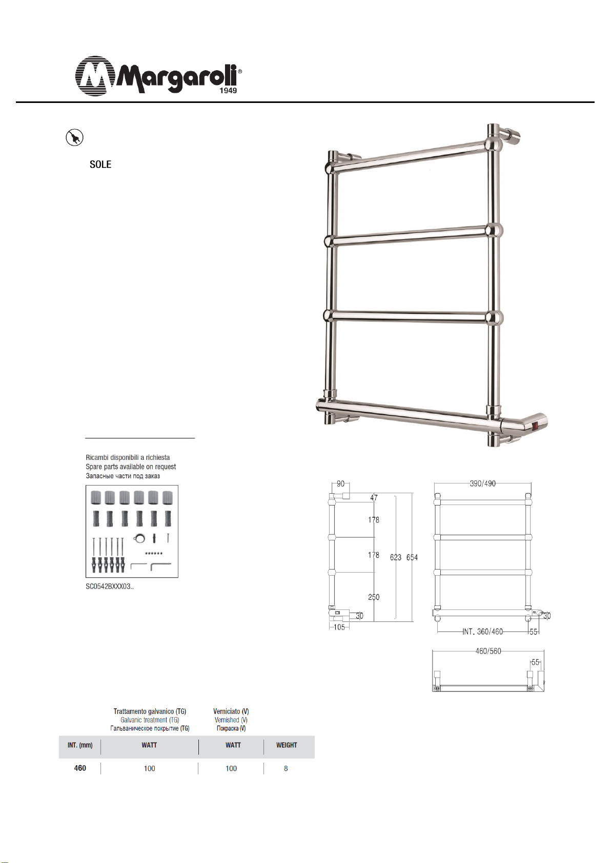
Scaldasalviette fisso componibile,
con particolari quadri 30mmX30mm
MISURA DEL TUBO: Ø25mm
MODULO AGGIUNTIVO: 180mm
COLLEGAMENTO ELETTRICO: scatola
interruttore con tasto on/off (BOX)
RESISTENZA: cartuccia riscaldante
FILO CON PRESA SCHUKO: disponibile
AROMATERAPIA: disponibile
Fixed modular heated towel rail
with squared parts 30mmX30mm.
PIPE DIMENSION: Ø25mm
ADDITIONAL MODULE: 180mm
ELECTRIC CONNECTION: on/off switch box (BOX)
ELECTRIC ELEMENT: cartridge heater
WIRE AND SCHUKO PLUG: available
AROMATHERAPY: available
Модульный стационарный полотенцесушитель
с квадратными элементами 30ммХ30мм.
ДИАМЕТР ТРУБЫ : Ø25мм
ДОПОЛНИТЕЛЬНЫЙ МОДУЛЬ: 180мм
ЭЛЕКТРИЧЕCКОЕ ПОДКЛЮЧЕНИЕ: коробка
выключателя с кнопкой вкл./выкл. (BOX)
ЭЛЕКТРИЧЕСКИЙ НАГРЕВАТЕЛЬНЫЙ ЭЛЕМЕНТ:
патронный нагреватель
КАБЕЛЬ С ЕВРО РОЗЕТКОЙ: в наличии
АРОМАТЕРАПИЯ: в наличии

Art 542/TQ
Materia prima: Ottone
Funzionamento: Elettrico
Si è elaborato il seguente manuale d’uso allo scopo di
fornire le informazioni appropriate per l’installazione e le
precauzioni da adottare da parte dell’installatore e
dell’utilizzatore. Il costruttore declina ogni
responsabilit in caso di utilizzo dell’apparecchio al di
fuori delle istruzioni fornite.
Il cavo d’alimentazione e’ collegato all’apparecchio con un
collegamento di tipo z, quindi non puo’ in alcun modo e
per nessun motivo essere sostituito in caso di
danneggiamento. Un’operazione di questo tipo renderebbe
l’apparecchio pericoloso e farebbe decadere ogni
responsabilita’ da parte del costruttore.
ATTENZIONE: Questo apparecchio può essere utilizzato
solo per supporto di asciugamani o simili.
L’apparecchio nel suo normale utilizzo non deve essere
caricato con un peso superiore a 5Kg
Utilizzare solo le viti e i tasselli in dotazione o sostituirli con
altre di uguali o maggiori caratteristiche di tenuta
meccanica
GRADO DI PROTEZIONE: pparecchio protetto contro gli
spruzzi IPX4.
IMPORTANTE:
IL COLLEGAMENTO ELETTRICO TRA
L’APPARECCHIO E LA RETE DEVE ESSERE
ESEGUITO DA PERSONALE QUALIFICATO E
CON LA RETE ELETTRICA DISATTIVATA
CONTENUTO DELLA CONFEZIONE : (vedi immagine 1)
(1) Scaldasalviette
(1) Chiave a brugola esagono 3
(4) Grani per fissaggio supporto a muro M6X6
(4) Supporti a muro
(4) Viti con tasselli per fissaggio a muro
(4) Supporti da fissare a muro
(1) Boccola per Box
(1) Tassello e vite per boccola per box
INSTALLAZIONE: (vedi disegno 2)
Rimuovere lo scaldasalviette e i suoi componenti
dall’imballo
Per il montaggio appoggiare l’articolo al muro, dopo aver
ruotato verso il lato desiderato (DX o SX) la scatola con
interruttore, facendola coincidere con l’uscita dalla parete
dei cavi di alimentazione della rete, segnare la posizione
del foro della boccola di sostegno della scatola interruttore
a questo punto eseguire 1 foro con punta Ø 4 nel muro ed
inserirvi il tassello in dotazione.
Conseguentemente ruotare gli attacchi a muro superiori e
inferiori. Segnare la posizione dei supporti a muro ed
eseguire 4 fori con una punta Ø 8 nel muro in
corrispondenza degli attacchi a muro inferiori e superiori
“D” dello scaldasalviette ed inserirvi i tasselli “B”
ssicurarsi che il cappuccio “C” sia inserito nell’attacco a
muro “D”
Fissare al muro i 4 supporti “ ” tramite le relative viti “E”
Fissare i due attacchi a muro “F” opposti alla scatola
interruttore. Ruotare lo scaldasalviette e avvicinarlo al
muro per collegare i fili elettrici che escono dal muro ”G”
con le connessioni che escono dalla scatola interruttore
“H” per fissare gli altri due attacchi a muro e la boccola “M”
di fissaggio della scatola interruttore.
Tramite la chiave a brugola presente nella confezione,
serrare il grano posto inferiormente ad ogni attacco a muro
in modo che lo scaldasalviette risulti parallelo alla parete
Far scorrere il cappuccio “C” fino ad arrivare in battuta
contro il muro.
Solo dopo aver eseguito questa operazioni potrete
riattivare il collegamento alla rete elettrica e verificare il
corretto funzionamento della scaldasalviette.
La ditta declina ogni responsabilità nel caso di montaggio
non corretto.
ATTENZIONE:
Qualora ci sia una fuoriuscita di liquido antigelo dagli
scaldasalviette assicurarsi di evitare il contatto con gli
occhi, evitare inalazione, evitare ingestione e contatto con
la pelle
Raw material : Brass
Operation: Electrical
The following manual has been elaborated in order to
supply all the useful information for a correct installation
together with the precautions to adopt both from installer
and users. Manufacturer declines every responsibility
in case of different uses from these instructions.
The heated towel rails is connected to the mains with a z
type connection, and consequently it cannot be
substituted in any case of damage. Such an action would
make the item dangerous and free the producer from
every responsibility.
ATTENTION :This item can be only used as holder for
towels and similar garments.
This item, in normal use, cannot be loaded with more than
5 Kg. weight.
Please, only use provided screws and dowels or replace
them with other ones equivalent or greater in mechanical
characteristics.
PROTECTION DEGREE: Squirts resistant IPX4.
IMPORTANT:
THE ELECTRICAL CONNECTION BETWEEN
ITEM AND MAINS MUST BE EXECUTED BY
QUALIFIED STAFF AND AFTER TURNING OFF
ELECTRICITY AT THE MAIN PANEL.
PACKING CONTENTS : (see image 1)
(1) Heated towel rail
(1) llen key
(4) Screw for upper brackets M6X6
(4) Sliding caps
(4) Screw with dowel
(4) Brackets holder
(1) Box bush
(1) Dowel and screw for box bush
INSTALLATION: (see design 2)
Take out the heated towel rail and its components from the
package.
To mount the heated towel rails, lean it against the wall,
then rotate the switch box to the desired side (Left or
Right) and let it coincide with the mains output from the
wall. Mark the position of the hole of box bush.
Then make a hole into the wall with a Ø 4 drill and insert
the provided dowel. Consequently rotate the upper and
bottom wall brackets. Mark their position and make four
holes with a Ø 8 drill in correspondence of the upper and
bottom wall brackets “D” and insert the provided dowels.
“B”
Make sure that the cap “C” has been stringed in the wall
bracket “D”
Fix the four wall bracket “ ” to the wall by the proper
screws “E”
Fix the two wall brackets “F” at the opposite side of the
wall switch box. Rotate the item and approach it to the wall
to connect the electrical whirls coming out from the wall
“G” to the cables exiting from the switch box “H” and then
fix the other two wall brackets and “M” box bush.
Only after finishing this action, you can turn the power on
and verify the heated towel rails works correctly.
Using the provided allen key now, tight the little screw
present under every wall bracket, so that the heated towel
rail looks parallel to the wall.
Let every cap “C” to slide adherent to the wall.
Our Company refuses any responsibility in the case the
assembly doesn’t respect the above mentioned instruction.
WARNING:
Whether a leakage of antifreeze liquid occurs from our
electrical towel heaters, take care not to permit any contact
with eyes and skin and avoid inhalation or ingestion
1)
542/B…….. 542/P…..
2)
ATTENZIONE: NON smaltire lo scaldasalviette come normale rifiuto urbano, ma effettuare una
raccolta separata e uno smaltimento in apposito centro attrezzato.WARNING: DO NOT get rid of
this item as urban waste, but swallow it separately or by properly equipped institutes.
This manual suits for next models
1
Other Margaroli Home Bathroom Fixture manuals

Popular Bathroom Fixture manuals by other brands

Kohler
Kohler Mira Sport Max J03G Installation and user guide

Moen
Moen 186117 Series installation guide

Hans Grohe
Hans Grohe Raindance Showerpipe 27235000 Instructions for use/assembly instructions

Signature Hardware
Signature Hardware ROUND SWIVEL BODY SPRAY 948942 Install

fine fixtures
fine fixtures AC3TH installation manual

LIXIL
LIXIL HP50 Series quick start guide


