Marine PC MPC-PPC12 User manual

MPC-PPC12 Manual
December 2012
N
S
E
W
MARINE PC
MARINE PC
MPC-PPC12
Marine Grade 12.1” LCD Monitor
with
1.8 GHZ Dual Core Computer

i
Copyright Notice
This document is copyrighted, 2012. All rights are reserved. The
original manufacturer reserves the right to make improvements to
the products described in this manual at any time without notice.
No part of this manual may be reproduced, copied, translated, or
transmitted in any form or by any means without the prior written
permission of the original manufacturer. Information provided in
this manual is intended to be accurate and reliable. However, the
original manufacturer assumes no responsibility for its use, or for
any infringements upon the rights of third parties that may result
from its use.
The material in this document is for product information only and is
subject to change without notice. While reasonable efforts have
been made in the preparation of this document to assure its
accuracy, MarinePC assumes no liability resulting from errors or
omissions in this document, or from the use of the information
contained herein.
MarinePC reserves the right to make changes in the product
design at any time without notice to its users.

ii
Acknowledgments
All other products’ name or trademarks are properties of their
respective owners.
AMI is a trademark of American Megatrends Inc.
Intel®, and Atom™ are trademarks of Intel®Corporation.
Microsoft Windows®is a registered trademark of Microsoft
Corp.
IBM, PC/AT, PS/2, and VGA are trademarks of International
Business Machines Corporation.
All other product names or trademarks are properties of their
respective owners.

iii
Packing List
Before you begin operating your PC, please make sure that the
following materials are enclosed:
MPC-PPC12 Panel PC
Power Terminal Block
Mounting brackets and screws
DVD-ROM for manual (in PDF format) and drivers
If any of these items should be missing or damaged, please contact
your distributor or sales representative immediately.
Operating System Distribution Media (if Ordered)

iv
Safety & Warranty
1. Read these safety instructions carefully.
2. Keep this user's manual for later reference.
3. Disconnect this equipment from power outlet before cleaning. Do
not use liquid or spray detergents for cleaning. Use a damp cloth.
4. For pluggable equipment, the power outlet must be installed near
the equipment and must be easily accessible.
5. Keep this equipment away from excessive moisture.
6. Put this equipment on a firm surface during installation. Dropping
it or letting it fall could cause damage.
7. The openings on the enclosure are for air convection. Protect the
equipment from overheating. DO NOT COVER THE OPENINGS.
8. Make sure the voltage and polarity of the power source is correct
before connecting the equipment.
9. Position the power cord so that people cannot damage on it. Do not
place anything over the power cord.
10. All cautions and warnings on the equipment should be noted.
11. If the equipment is not used for a long time, disconnect it from the
power source to avoid damage by transient over-voltage.
12. Never pour any liquid into an opening. This could cause fire or
electrical shock.
13. Never open the equipment. For safety reasons, only qualified
service personnel should open the equipment.
14. If any of the following situations arises, get the equipment
checked by service personnel:
a. The power plug or any connector is damaged.
b. Liquid has penetrated into the equipment.
c. The equipment has been damaged.

v
d. The equipment does not work well, or you cannot get it
to work according to the user’s manual.
e. The equipment has been dropped.
f. The equipment has obvious signs of breakage.
15. DO NOT LEAVE THIS EQUIPMENT INAN ENVIRONMENT
WHERE THE STORAGE TEMPERATURE IS BELOW -20°C
(-4°F) OR ABOVE 70°C (158°F). IT MAY DAMAGE THE
EQUIPMENT.
FCC
This device complies with Part 15 FCC Rules.
Operation is subject to the following two
conditions: (1) this device may not cause
harmful interference, and (2) this device must
accept any interference received including
interference that may cause undesired
operation.
Caution:
There is a danger of explosion if the battery is incorrectly replaced.
Replace only with the same or equivalent type recommended by the
manufacturer. Dispose of used batteries according to the
manufacturer’s instructions and your local government’s recycling or
disposal directives.

vi
NOTES

vii
Contents
Chapter 1 General Information
1.1 Introduction................................................................1-2
1.2 Specification..............................................................1-3
1.3 Dimension.................................................................1-6
Chapter 2 Hardware Installation
2.1 Panelmount Installation.............................................2-2
2.2 COM 1/2 RS-232/422/485 Serial Port Connector.....2-4
2.3 CompactFlash™ Installation.....................................2-5
2.4 Hard Disk Drive Installation.......................................2-6
Chapter 3 AMI BIOS Setup
3.1 System Test and Initialization...................................3-2
3.2 AMI BIOS Setup........................................................3-3
Chapter 4 Driver Installation
4.1 Introduction................................................................4-3
Appendix A AHCI Setting
A.1 WINDOWS OS Installation........................................A-2

Chapter 1 GeneralInformation 1- 1
General
Chapter
1
Information

Chapter 1 GeneralInformation 1- 2
1.1 Introduction
The MPC-PPC12 panel PC is an Intel ®Atom™ D525 1.8 GHz
processor computer that is designed to serve as a human machine
interface (HMI). It is a PC-based system with 12.1" color TFT LCD
display, onboard Ethernet controller, multi-COM port interfaces and
an audio controller. With a built-in CompactFlash socket, the
MPC-PPC12 is a compact and very user friendly multi-function
computer. In addition, its "fit anywhere" design makes it very
flexible and able to be used in many different kinds of installations.
It can be VESA 100 arm mounted.
For system integrators, this simple, complete, compact and highly
integrated system let you easily build into a bridge console for your
applications. Common applications include use as a chart plotter,
vessel mangement system or NMEA2000 controller.
The MPC-PPC12 is a highly functional, flexible and cost effective way
of introducing open architecture systems into the marine enviroment.

Chapter 1 General Information 1-3
1.2 Specification
System
CPU Onboard Intel®Atom™ D525 1.8 GHz
Processor
System Memory DDR3 SODIMM x 1, Max. 4 GB
LCD / CRT Controller Integrated in Processor
I/O Port USB2.0 x 4
RS-232 x 1
RS-232/422/485 x 1
LAN x 2
VGA x 1
Line-out x 1
Storage Disk Drive CompactFlash™ slot x 1 (Internal);
2.5” SATA Hard Disk Drive x 1
OS Support Windows®XP, Windows®7, Linux
Fedora, Windows®CE
Mechanical
Construction IP-65/NEMA4 for aluminum die cast
front bezel & iron chassis
Mounting Panel/ Wall/ VESA 100/ Desktop
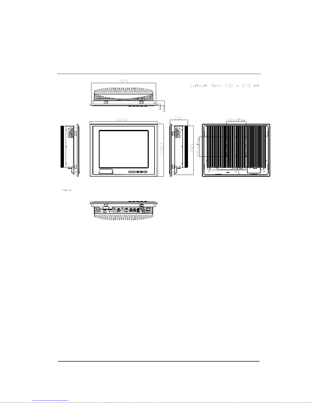
Dimension 13.6”(W) x 10.46”(H) x 3.58”(D)
(345.6mm x 265.7mm x 91mm)
Carton Dimension 17.9”(W) x 12.6”(H) x 15.75”(D)
(455mm x 320mm x 400mm)

Chapter 1 General Information 1- 4
Net Weight 15.4 lb (7 kg)
Gross Weight 19.8 lb (9 kg)
Environmental
Operating Temperature -4oF~140oF (-20oC~60oC)
Storage Temperature -4oF~158oF (-20oC~70oC)
Operating Humidity 10% to 95%@ 40oC, non-condensing
Vibration 1 g rms/ 5-500Hz/ Operation—With
Hard Disk Drive
Shock 20 G peak acceleration (11 msec.
duration)
EMC CE/FCC Class A
Power Supply 9~30V DC input ;
Over-voltage protection
Low-voltage protection
Reverse protection
LCD
Display Type 12.1” TFT LCD
Max. Resolution 1024x768
Max. Colors 262K
Luminance (cd/m2) Standard : 500 cd/m2
Hi-Brightness : 1000 cd/m2
Viewing Angle 160o(H),140o(V)

Chapter 1 General Information 1-5
Backlight LED
Backlight MTBF (Hours) 50,000
Touch Screen
Type 5-wire analog resistive
Resolution 2048x2048
Light Transmission > 80%
Lifetime35 million activations
Chapter 1 GeneralInformation 1- 6
1.3 Dimension

ediuGnoitallatsnIkciuQ2retpahC 2-1
Hardware
Installation
Chapter
2

Chapter 2 Quick Installation Guide 2 - 2
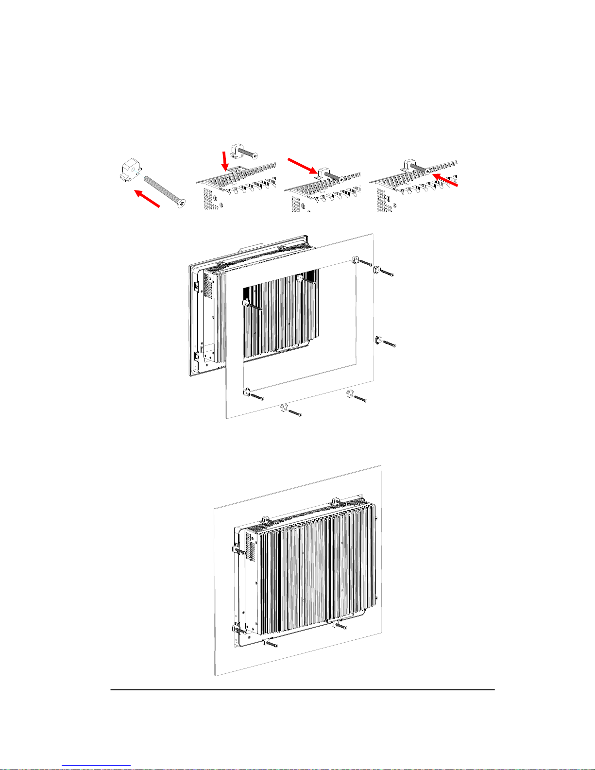
2.1 Panelmount Installation
The display panel can be mounted into the wall. You will need the
screws along with the mounting brackets, which be packed in the
accessory box. Follow the steps below:
Before you start to follow the instructions, please place the
display panel into the wall. See the following illustration on the
left.
Step 1: Place the mounting brackets and plug the screw.
Step 2: Aim the mounting set at the hole on the monitor.
Step 3: Move the mounting set to the narrow gauge and fix it with
screws.
Step 4: You’ve completed the preliminary when the mounting set
is tightened. Next, repeat the steps and tighten all mounting set
around the monitor until the monitor is firmly mounting on the
wall.
Chapter 2 Quick Installation Guide
2 - 3
1 2 3 4
Complete Illustration

Chapter 2 Quick Installation Guide 2 - 4
2.2 COM1/2 RS-232/422/485 Serial Port Connector
COM1 (D-sub 9 male)
Pin2BSignal Pin3BSignal
1 DCD 2 RXD
3 TXD 4 DTR
5 GND 6 DSR
7 RTS 8 CTS
9 RI
COM2 RS-232/422/485 (D-sub 9 male)
Pin Signal Pin Signal
1DCD
(422TXD-/485DATA-)2 RXD (422RXD+)
3TXD
(422TXD+/485DATA+) 4 DTR (422RXD-)
5 GND 6 DSR
7 RTS 8 CTS
9 RI/+5Volt/+12Volt
1
24
5
6
78
9
1
24
5
678
9
Chapter 2 Quick Installation Guide
2 - 5
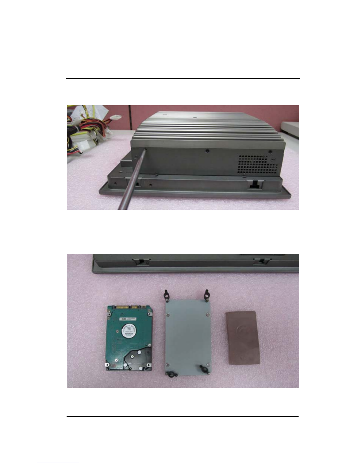
2.3 Hard Disk Drive Installation
Step 1: Unfasten the screws of the heatsink
Step 2: Get the Bracket of Hard Disk Drive and Thermal Pad from the
package

Chapter 2 Quick Installation Guide 2 - 6
Step 3: Stick the Thermal Pad onto the Hard Disk Drive and fasten the
Hard Disk Drive onto the bracket
Step 4: Fasten the screws of the hard disk bracket onto the MPC-PPC12
Table of contents
Popular Boating Equipment manuals by other brands


Humphree
Humphree HCS-5 installation manual

Vetus
Vetus BOW4512D Operation manual and installation instructions

Dock Doctors
Dock Doctors SLIDING BOARDING STEP Assembly instructions

Mastervolt
Mastervolt Mass Combi 12/2000-100 Quick installation

SeaView
SeaView PM5-FMD-8 installation instructions

Hobie
Hobie Mirage 360 manual


