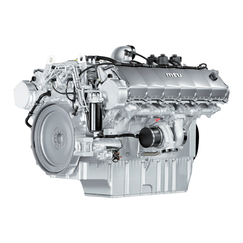
Marine Power 5.3 GEN V DI User manual

4.3L/5.3L/6.2L/LT4
MEFI 7 DIRECT INJECTION
ENGINE OWNER’S MANUAL
VERSION 4

i www.MarinePowerUSA.com
Table of Contents
Section 1: introduction
ProPosition 65......................................................................1
safety Warnings ....................................................................1
rePlacement Parts...................................................................1
safe Boating .........................................................................2
Warranty ..........................................................................2-6
Section 2: Safe Boating
carBon monoxide exPosure........................................................6
Section 3: engine identification
engine tyPe...........................................................................7
model sPecifications................................................................8
Section 4: electronic Sequential fuel injection
information ............................................................................9
Section 5: engine alarmS and inStrumentation
digital alarms......................................................................10
instrumentation ....................................................................11
Section 6: SSVec fuSe and relay encloSure ......................12-15
Section 7: PrecautionS
oil level ............................................................................16
Hydrolock ..........................................................................16
Section 8: engine oPerating inStructionS
gasoline requirements............................................................17
oil requirements ..................................................................17
starting engine efi...............................................................17
engine Break-in/25 Hour insPection.....................................17-18
Section 9: Winterization
4.3/5.7l raW Water cooled engines .......................................19
full closed cooled engines .....................................................20
Half closed cooled engines................................................21-22
full closed inBoard Jet engines ................................................23
Section 10: engine maintenance
scHeduled maintenance By oWner ..............................................24
scHeduled maintenance By qualified tecHnician...............................25
crankcase oil cHange.............................................................26
oil filters ..........................................................................27
flame arrestor ....................................................................28
g-force fuel system .............................................................28
Battery caBles .....................................................................29
multiPle engine Battery Precautions - efi ....................................29
alternator Belt tension ..........................................................29
sea Water PumP imPeller rePlacement.........................................29
closed cooling system...........................................................30
filling closed cooling system .............................................30-31
Section 11: engine diagnoSticS and codeS ........................32-34
Section 12: trouBle Shooting
engine Will not turn over .....................................................35
engine cranks But Will not start.............................................35
engine runs Poorly at HigH rPm..............................................36
HigH sPeed miss ..................................................................36
fuel system - ricH ................................................................37
fuel system - lean................................................................37
Poor fuel economy ...............................................................37
engine starts and stoPs .........................................................38
oil Pressure - loW................................................................38
oil Pressure - HigH ...............................................................38
excessive oil consumPtion.......................................................39
engine overHeating................................................................39
Water in engine cylinder or Base ..............................................40
Section 13: inStallation inStructionS
engine comPartment...............................................................41
engine mounting ..................................................................41
engine rotation ....................................................................41
engine Bed..........................................................................41
cooling system...............................................................41-42
emission-related installation instructions.....................................42
exHaust PiPing ................................................................42-43
electrical connection .............................................................43
Batteries ............................................................................43
dual engines .......................................................................43
Battery isolators ..................................................................43
engine Battery sPecifications ....................................................44
Battery caBle lengtH requirements.............................................44
sPecial fuel instructions for 6.2 550 HP engines........................44
lsa airBoat installation notes .................................................45
adaPter Harness...................................................................46
Heater connections ...............................................................47
Prestart cHecklist .................................................................48
Potentiometer oPeration..........................................................49
Warranty regiStration tranSfer .............................................50
SerVice log......................................................................51-53

1www.MarinePowerUSA.com
DANGER
WARNING
CAUTION
DANGER
WARNING
CAUTION
DANGER
WARNING
CAUTION
1. Introduction
Marine Power would like to thank you again for your pur-
chase. The pleasure and peace of mind derived from your new
engine is in direct proportion to the amount of care that it is
given. We have tried to include as much as possible in our Engine
Owner’s Manual to help you as the customer. READ THIS
MANUAL THOROUGHLY AND COMPLETELY before attempting
to operate your Marine Power engine. We ask that you become
familiar with the components and the maintenance schedules. If
you have any questions or concerns regarding this manual or your
newly purchased Marine Power engine, please feel free contact
your nearest Marine Power dealer or distributor.
Proposition 65
“Safety Warnings” and additional information or instructions are
used to alert the installer/operator of possible safety hazards in
performing certain service or maintenance procedures incorrectly
or carelessly.
These “Safety Warnings” alone cannot eliminate the hazards
that they signal. Strict compliance with these warning instruc-
tions while performing service and maintenance procedures,
plus “common sense” operation, are major accident prevention
measures.
The engine exhaust from this product contains chemicals
known to the State of California to cause cancer, birth defects
or other reproductive harm. The LT4 Is a Premium 93 Octane REQUIRED engine. The
engine will operate at significantly reduced power output with
octane levels down to 90. Operating the LT4 on fuel below
90 Octane can result in engine damage and or failure! Such
failure will not be covered under warranty!
Electrical, ignition and fuel system components are designed
and manufactured to comply with U.S. Coast Guard rules and
regulations to minimize the possibility of fire or explosion
hazard.
Safety Warnings
Signals serious damage, failure or breakdown of equipment;
severe injury or high probability of death to the user if proper
precautions are not taken. This signal word is applied in extreme
situations.
Indicates a potential hazard which could result in personal injury.
Indicates a hazard which could result in damage to equipment.
Replacement Parts
Use of replacement parts (i.e. automotive, after-market, etc.) in the
electrical, ignition and fuel systems, which are not U.S. Coast Guard
approved, could cause a fire or explosion hazard and must be avoided.
Always request that genuine Marine Power engine replacement
parts be used in any repairs or maintenance being performed on
your engine(s).
DANGER
WARNING
CAUTION
DANGER
WARNING
CAUTION
DANGER
WARNING
CAUTION

2www.MarinePowerUSA.com
1. Introduction
Safe Boating
The waterways are becoming increasingly crowded and, in order
to enjoy them safely, the operator should acquaint himself/her-
self with safe boating practices. Boating safely and seamanship
ourses are offered by the following national and state organi-
zations:
• Power Squadrons
• Coast Guard Auxiliary
• Red Cross
• State, provincial or local agencies in charge of water safety
enforcement
Marine Power recommends that all power boat operators attend
one of these courses.
To help locate a course being offered near you, contact Boat
U.S. Foundation’s toll-free national boating safety hotline,
1-800-336-BOAT, and in Virginia, 1-800-245-BOAT.
The Federal Boat Safety Act of 1971 requires that registration of
marine products sold in the United States be maintained by the
manufacturer and dealers of those products. It is imperative that
Marine Power Holding LLC receive your WARRANTY REGISTRA-
TION/SEA TRIAL form properly completed for warranty purpos-
es and to comply with federal regulation. This registration also
enables us to contact you, if it should become necessary, to change
or improve the product for your protection.
WARRANTY REGISTRATION MUST BE RECEIVED WITHIN 10
DAYS AFTER DATE OF PURCHASE BY FIRST OWNER.
Please read the Limited Warranty document that is included
with your engine registration papers and in this manual. This
document explains your warranty coverage. Please note that no
warranty repairs are to be performed without prior authorization
from the Marine Power Distributor in your area. Contact your
selling dealer directly for any required warranty repairs.
For more information, you may also visit our web site at
www.marinepowerusa.com.
Again, thanks for choosing Marine Power.
CALIFORNIA AND U.S. ENVIRONMENTAL PROTECTION AGENCY
EMISSIONS CONTROL WARRANTY STATEMENT
Your Warranty Rights and Obligations
The California Air Resources Board, U.S. E.P.A., and Marine Power
Holding LLC are pleased to explain the emission control system war-
ranty on your inboard engine. New Inboard engines must be designed,
built and equipped to meet California and EPA’s stringent anti-smog
standards. Marine Power Holding LLC must warrant the emission control
system on your Inboard engine for the periods of time listed on the next
page, provided there has been no abuse, neglect or improper mainte-
nance of your inboard engine.
Your emission control system may include parts such as fuel
injection system, the ignition system and catalytic converter. Also
included may be hoses, belts, connectors and other emission-
related assemblies.
Where a warrantable condition exists, Marine Power Holding LLC will
repair your inboard engine at no cost to you, including diagnosis, parts
and labor.

3www.MarinePowerUSA.com
1. Introduction
Manufacturer’s Warranty Coverage
THIS AGREEMENT GIVES YOU SPECIFIC LEGAL RIGHTS, AND
YOU MAY ALSO HAVE OTHER RIGHTS THAT VARY FROM JURIS-
DICTION TO JURISDICTION.
THERE IS NO OTHER EXPRESS WARRANTY. IMPLIED WARRAN-
TIES, INCLUDING THOSE OF MERCHANTABILITY AND FITNESS
FOR A PARTICULAR PURPOSE, ARE LIMITED TO THE APPRO-
PRIATE WARRANTY PERIOD IN THE ABOVE TABLE, OR TO THE
EXTENT PERMITTED BY LAW, ANY AND ALL IMPLIED
WARRANTIES ARE EXCLUDED. LIABILITY FOR INCIDENTAL OR
CONSEQUENTIAL DAMAGES ARE EXCLUDED TO THE EXTENT
EXCLUSION IS PERMITTED BY LAW. Some states or countries do
not allow limitations on how long an implied warranty lasts, and
some states or countries do not allow the exclusion or limitation of
incidental or consequential damages, so the above limitation and
exclusion may not apply to you. This warranty gives you specific
legal rights and you may also have other rights which vary from
state to state and country to country.
THE FOREGOING REMEDIES ARE EXCLUSIVE. MARINE POWER
MAKES NO OTHER EXPRESS WARRANTY. MARINE POWER SHALL
IN NO CIRCUMSTANCES BE LIABLE IN CONTRACT, IN TORT OR
OTHERWISE FOR SPECIAL, INCIDENTAL OR CONSEQUENTIAL
DAMAGES, WHETHER OR NOT FORESEEABLE. NO EMPLOYEE
OR REPRESENTATIVE OF MARINE POWER IS AUTHORIZED TO
MODIFY THIS WARRANTY, OR MARINE POWER’S STANDARD
WARRANTY FOR ANY PRODUCT.
MARINE POWER DOES NOT AUTHORIZE ANY PERSON TO
CREATE FOR MARINE POWER ANY OBLIGATION OR LIABILI-
TY OTHER THAN THAT STATED IN THE LIMITED WARRANTY.
UNDER NO CIRCUMSTANCES SHALL MARINE POWER BE LIABLE
TO THE CUSTOMER OR ANY OTHER PERSON FOR ANY CONSE-
QUENTIAL, INCIDENTAL, ECONOMIC, DIRECT, INDIRECT, GENER-
AL, OR SPECIAL DAMAGES ARISING OUT OF ANY BREACH OF
WARRANTY, EXPRESSED OR IMPLIED.
Owner’s Warranty Responsibilities
As the Inboard engine owner, you are responsible for the
performance of the required maintenance listed in your own-
er’s manual. Marine Power Holding LLC recommends that you
retain all receipts covering maintenance on your inboard engine,
but Marine Power Holding LLC cannot deny warranty solely for
the lack of receipts or your failure to ensure the performance
of all schedule maintenance. Marine Power highly recommends
that the selling dealer do Warranty Registration along with a
completed Statement of Sea Trial in order to facilitate any
warranty work necessary in the future.
As the Inboard engine owner, you should however be aware that
Marine Power Holding LLC may deny you warranty coverage if
your Inboard engine or part has failed due to abuse, neglect or
improper maintenance or unapproved modifications.
You are responsible for presenting your Inboard engine to a
Marine Power Holding LLC distribution center as soon as a prob-
lem exists. The warranty repairs will be complete within a rea-
sonable amount of time, not to exceed 30 days.
1. Marine Power Holding LLC (“Marine Power”) warrants to
the first owner purchasing at retail and all subsequent own-
Engine Type Power Electronic Mechanical
Rating Components Components
Conventional - OEM Less than or equal to 3 Years or 480 Hours 3 Years or 480 Hours
373 kW (500 HP)
Hi-Performance - OEM Between 373 kW (500 HP) 3 Years or 150 Hours 3 Years or 150 Hours
and 485 kW (650 HP)
Complete Engine Repower Less than or equal to 2 Years or 300 Hours 2 Years or 300 Hours
373 kW (500 HP)
Complete Engine Repower Between 373 kW (500 HP) 1 Year or 150 Hours 1 Years or 150 Hours
and 485 kW (650 HP)
Special Applications All 1 Year or 150 Hours 1 Years or 150 Hours

4www.MarinePowerUSA.com
ers, of every Marine Power Inboard marine engine manufac-
tured after January 1, 2008, that the emissions control devic-
es on Marine Power Inboard marine engines are free from
defects in materials and workmanship when manufactured
and will remain so for the stated period in the above table.
Marine Power warrants that each Marine Power Inboard
marine engine and factory installed accessories designed,
built and equipped with all applicable regulations adopted
by the Air Resources Board pursuant to its authority in Chap-
ters 1 and 2, Part 5, Division 26 of the Health and Safety
Code; and the U. S. Environmental Protection Agency pursu-
ant its authority in Chapter 9 of Title 5 of the U.S. Code to be
free from defects in materials and workmanship that cause
the failure of a warranted part to be identified in all material
respects to that part as described in the engine manufacturer
application for certification.
2. The warranty shall commence, on the date of delivery to
the first retail purchaser or from the date the engine is first
placed in service for demonstration or any other purpose
prior to the sale to the first retail owner. However, in no event
shall the duration of this warranty exceed three (3) years
measured from the original retail sale date.
3. Any warranted part that is not scheduled for replacement
as required maintenance in the written instructions in the
Owner’s Manual will be warranted for the appropriate
warranty period in the above table. If the part fails during
the period of warranty coverage, the part will be repaired or
replaced by Marine Power at a warranty station. Any such
part repaired or replaced under warranty will be warranted
for the remainder of the period.
4. Any warranted part that is scheduled only for regular inspec-
tion in the written instructions in the Owner’s Manual will be
warranted for the appropriate warranty period in the above
table. A statement in such written instructions to the effect of
“repair and replace as necessary” does not reduce the period
of warranty coverage. Any such part repaired or replaced
under warranty will be warranted for the remaining war-
ranty period.
5. Any warranted part that is scheduled for replacement as
required maintenance in the written instructions in the
Owner’s Manual will be warranted for the period of time
before the first scheduled replacement date for the part. If
the part fails before the first scheduled replacement, the part
will be repaired or replaced by Marine Power at a warranty
station. Any such part repaired or replaced under warranty
will be warranted for the remainder of the period to the first
scheduled replacement point for the part.
6. Repair or replacement of any warranted part under the
warranty provisions of the article will be performed at a
warranty station at no charge to the owner. Warranty services
and repairs will be provided at all Marine Power distribution
centers and trained marine dealers.
7. The engine owner will not be charged for diagnostic labor
that is directly associated with diagnosis of a defective,
emission related warranted part, provided that such
diagnostic work is performed at a warranty station.
8. Marine Power is liable for damages to other engine compo-
nents proximately caused by a failure under warranty of any
warranted part.
9. Throughout the appropriate warranty period in the table
from the previous page Marine Power will maintain a supply
of warranted parts sufficient to meet the expected demands
for such parts.
10. Any replacement part may be used in the performance of
any warranty maintenance or repairs and will be provided
without charge to the owner. Such usage will not reduce
Marine Power’s warranty obligations.
11. Add-on or modified parts, as defined in CCR, Section 1900
(b)(1) and (b)(10), Title 13, that are not exempted by the
Air Resources Board will not be used. The use of any non-
exempted add-on or modified parts by the ultimate purchas-
er will be grounds for disallowing a warranty claim made
in accordance with this article statement. Marine Power will
not be liable under this statement to warranted failures of
warranted parts caused by the use of non-exempted add-on
or modified part.
12. The following parts are covered by this general emissions
warranty statement.
A) Fuel Metering System
1) Fuel Injectors
2) Fuel Pressure Regulator
3) Manifold Absolute Pressure Sensor
4) Throttle Position Sensor
1. Introduction

5www.MarinePowerUSA.com
5) Throttle Body
6) Coolant Temperature Sensor
7) Oxygen Sensors
8) Intake Valves
B) Air Induction System
1) Intake Manifold
2) Air Filter/Flame Arrestor
C) Ignition System
1) Spark Plugs
2) Electronic Ignition System
3) Spark Advance/Retard System
4) Ignition Coil and/or Control Module
5) Ignition Wires
D) Lubrication System
1) Oil Pump and Internal Parts
E) Positive Crankcase Ventilation (PCV) System
1) PCV Valve
2) Oil Filler Cap
F) Exhaust System
1) Exhaust Manifolds and Risers
2) Exhaust Valves
3) Catalysts
G) Miscellaneous Items Used in Above Systems
1) Hoses, Clamps, Fittings, Tubing, Sealing Gaskets
or Devices and Mounting Hardware
2) Pulleys, Belts and Idlers
3) Vacuum, Temperature, Check and Timer Sensitive
Valves and Switches
4) Electronic Controls
13. The repair or replacement of any warranted part otherwise
eligible for coverage under this warranty may be denied
from such warranty coverage if Marine Power demonstrates
that the engine and/or part has been abused, neglected, or
improperly maintained, and that such abuse, neglect, or
improper maintenance was the direct cause of the need for
repair or replacement of the part.
14. This Warranty will not apply to:
A) Use of an accessories or parts not manufactured or sold by
Marine Power.
B) Neglect, failure to follow maintenance schedules,
accident, abnormal operations, misuse, negligence,
improperly maintained, improperly operated or
installed, racing or engine modification. Problems
arising from installation, application, exhaust to engine,
fuel lines to the engine, propping, cooling to the engine
or engine damage due to defective electrical hookups.
C) Rust, corrosion or effects of weather.
D) Water ingestion through exhaust or intake system.
E) Detonation or operation with fuels, oils or lubri-
cants which are not suitable for use with this product.
Detonation causes: Poor fuel quality, overloading of
engine, improper gear or propeller selection, engine
1. Introduction
overheating, excessive back pressure, incorrect ignition
timing, excessive total timing.
F) Reimbursement for: Haul-out, launch, towing, storage
charges, rental charges of any type, inconvenience of
any type, loss of time or income, expense of returning a
Marine Power product to a service facility, towing, lodg-
ing, loss or damage to personal property.
G) Carburetor replacement and labor is limited to mechani-
cal defects only. Replacement does not extend to contam-
inated fuel, varnish or other residues, changes in fuel
mixtures, poor octane fuel or adjustments beyond five (5)
hours of engine operation.
15. Marine Power reserves the right to limit warranty coverage
on engines that have accumulated excessive hours through
commercial use or any other non-typical operation.
Special Applications Warranty
Marine Power Engines that are used in inboard mud boat
applications (“Special Applications”) carry a strict limited war-
ranty. The warranty period applicable to Special Applications
such as inboard mud boat usage, shall carry a limited warranty
period of one (1) year or 150 hours, whichever occurs first. This
warranty shall only cover and be strictly limited to the repair or
replacement of parts located from the flywheel forward. Repair
or replacement of drive plates are specifically not covered. Any
and all transmission warranties must be handled by the transmis-
sion manufacturer directly. Marine Power’s emission warranty
shall not be limited by these specific limitations. This warranty

6www.MarinePowerUSA.com
2. Damages caused by extreme temperatures in the exhaust
system, including, but not limited to any occurrences of fire,
etc.;
3. Damages caused by or are the result of any sudden impact to
the propeller or any other part of the engine or its accesso-
ries;
4. Damages or failure of the damper drive plate.
Carbon Monoxide is a hazardous gas that is produced when items
containing carbon are burned. Items such as, but not limited to; wood, coal,
gasoline, natural gas, propane or oil. Carbon Monoxide (CO) is found
in many areas such as any type of internal combustion engines, heat-
ers, charcoal grills, cooking ranges and any other open flame applianc-
es. There are many possible variables for the accumulation of carbon
monoxide. Wind direction, boat speed, vessel proximity to other vessels or
structures are just a few of the possible variables that would permit
exposure to carbon monoxide gases. It is important that regular inspec-
tions of the exhaust system are conducted and maintenance is properly
performed by a qualified technician. Adequate air circulation in all
areas of your boat are necessary in order to prevent build-up of carbon
monoxide. Please contact your boat manufacturer if you have questions
regarding these hazards.
For more information regarding safe boating practices, and/or carbon
monoxide poisoning on recreational boats, contact the following:
National Marine Manufacturers Association (NMMA)
200 East Randolph Drive, Suite 5100, Chicago, IL 60601
312-946-6200 • www.nmma.org
United States Coast Guard
Office of Boating Safety Chicago, IL - CG Headquarters G-OPB-3
2100 Second Street, SW, Washington, DC 20593
202-267-0984 • www.uscgboating.org
American Boat & Yacht Council, Inc. (ABYC)
3069 Solomons Island Road, Edgewater, MD 21037-1416
410-956-1050 • www.abyc.com
covers engine related defective material and/or workmanship
only, and not replacement or refund of the equipment to which
the engine may be mounted.
This Special Applications Warranty shall NOT apply to nor shall it
extend to repairs required because of the following:
1. Damages caused by failures or inadequacies in the cooling
system;
1. Introduction
2. Safe Boating
DANGER
WARNING
CAUTION
Carbon Monoxide Exposure
Carbon Monoxide is a odorless, colorless and tasteless gas that cannot be
smelled, seen or tasted.
Sustained exposure to carbon monoxide gas may lead to brain damage,
unconsciousness or death.

7www.MarinePowerUSA.com
3. Engine Identication
Every Marine Power Engine is equipped with an Engine Identifi-
cation Tag, also known as a Serial Number Tag. This tag contains
information (model number and serial number) that will be
required before any warranty work (if necessary) can be done.
Airpac:
Engines configured for airboat applications. These engines use
closed cooling systems with automotive style radiators. Their
exhaust manifolds are dry and usually supplied by the boat
builder.
Enpac:
Engines configured for stern drive (I/O) applications. Cooling
water supply differs depending on the stern drive model mated
to. See Section 12: Installation Instructions.
Jetpac:
Engines configured for inboard jet drive applications. Cooling
water normally supplied by jet drive. Routing of inlet out out-
let cooling water lines will affect winterization. See Section 9:
Winterization procedures.
Towpac:
Engines configured for watersport tow boat applications. Engines
may be configured for conventional inboard or v-drive applica-
tion. In many of these applications throttle and shift is highly
integrated with the boat instrumentation
Sportpac:
Engines configured for traditional inboard vessels. Many of these
applications are twin installations.

8www.MarinePowerUSA.com
3. Engine Identication
Engine Type
Repower
Original Equipment
Unique Feature
Displacement
Bore & Stroke
Compression Ratio
Cylinder Block
Cylinder Head
Recommended Fuel
Max RPM @ Wot
Idle RPM
HP Fuel Pressure
LP Fuel Pressure
Oil Pressure @ 2000 RPM
Min Oil Pressure @ Idle
Operating Temp RW Cooled
Operating Temp FW Cooled
Sparkplug Type
Sparkplug Gap
Timing @ Idle
Timing @ 4000 RPM
Firing Order
Alternator Rating
Crankcase Oil
Oil Capacity
Closed Cooling Fluid
Closed Cooling Capacity
5.3 GEN V DI
V8
X
X
Direct Injection
5.3L/327 CID
96 x 92 mm
11 : 1
Aluminum
Aluminum
87 Octane
5600
ECM Controlled
60 PSI
4-7 PSI
30-60 PSI
10 PSI
N/A
175° F
12622441
.040”
ECM Controlled
ECM Controlled
1-8-7-2-6-5-4-3
150 amps
Dexos 15W50 GEN 2
8 Qts.
Antifreeze/Water
10 Qts.
6.2 LT4
V8
X
X
DI Supercharged
6.2L/374 CID
103.25 x 92 mm
10 : 1
Aluminum
Aluminum
93 Octane
5600
ECM Controlled
72 PSI
4-7 PSI
30-60 PSI
10 PSI
N/A
170°-190° F
12642722
.040”
ECM Controlled
ECM Controlled
1-8-7-2-6-5-4-3
250 amps
Dexos 15W50 GEN 2
8 Qts.
Antifreeze/Water
10 Qts.
6.2 GEN V DI
V8
X
X
Direct Injection
6.2L/374 CID
103.25 x 92 mm
11 : 1
Aluminum
Aluminum
87 Octane
5600
ECM Controlled
60 PSI
4-7 PSI
30-60 PSI
10 PSI
N/A
170°-190° F
12622441
.040”
ECM Controlled
ECM Controlled
1-8-7-2-6-5-4-3
150 amps
Dexos 15W50 GEN 2
8 Qts.
Antifreeze/Water
10 Qts.

9www.MarinePowerUSA.com
4. Electronic Sequential Fuel Injection Information
The engines covered in this manual are equipped with
Electronic Sequential Fuel Injection. The main fuel system
components include:
• The electric high and low pressure fuel pumps
• The throttle body assembly
• The fuel injectors
The fuel injection system is controlled by an Electronic Control
Module (ECM). The ECM continually monitors information from
the various sensors on the engine and configures the spark
timing and fuel delivery for optimum performance. Additionally,
the ECM protects the engine from over-revving and monitors the
oil pressure and water temperature.
The following sensors constantly provide information to the
ECM.
• Engine Coolant Temperature (ECT) Sensor
• Engine Oil Pressure Sensor
• Manifold Absolute Pressure (MAP) Sensor
• Knock Sensor
• Camshaft Positioning (CMP) Sensor
• Crankshaft Positioning (CKP) Sensor
• Intake Air Temperature (IAT) Sensor (combined with the
MAP sensor on the 5.7)
• Throttle Position (TPS) Sensor
• Pedal Position (PPS) Sensor
• Pre-Catalyst O2 (O2) Sensor (Catalyst equipped engines)
• Post-Catalyst O2 (O2) Sensor (Catalyst equipped engines)
Engines may include one or more of the following optional
sensors.
• Engine Oil Temperature Sensor
• Fuel Pressure Sensor
• Transmission Oil Temperature Sensor
• Exhaust Manifold Temperature Sensor
• Barometric Pressure (BARO) Sensor
• Super Charger Inlet Pressure (SCIP) Sensor

10 www.MarinePowerUSA.com
5. Engine Alarms and Instrumentation
Digital Alarms
If, for any reason, one or more of these sensors or associated
wiring malfunctions, the ECM’s built in self-diagnostic system sets
a trouble code and turns on the Malfunction Indicator Light (MIL)
or sounds a buzzer to alert the operator of a malfunction.
The MIL, buzzer and gauges can signal that something is wrong
before it becomes serious enough to cause an expensive repair.
Paying attention to the MIL, buzzer and gauges could also save
you or others from injury. The MIL may be replaced by verbiage
such as “Service Required” on boats equipped with electronic
instrumentation.
The MIL or “Service Required” notice comes on when there is a
problem with an engine function. Gauges can also indicate when
there is a problem with an engine functions. Often gauges and the
MIL (Service Required) work together to let you know that there is
a problem with your engine.
In most cases, when the “MIL” is on, the engine(s) may lose some
performance and/or efficiency, but remain running adequately.
Also, the light may go out or become intermittent, but a trouble
code will be logged for future diagnosis. In any case, the operator
must obtain service by an authorized dealer to determine and
repair the exact cause of the malfunction.
The engine ECM is programmed to control the engine alarm
system. This system is configured to turn on an instrument
panel mounted indicator (“MIL” or “Check Engine”) light, and,
optionally, an audible (“buzzer”) alarm to warn the operator of
engine problems.
If the “MIL” lights and/or the “buzzer” sounds during opera-
tion, the operator should scan the instrument panel readings for
possible sources of trouble. Conditions that may cause alarm ac-
tivation include:
• Low Oil Pressure
• Engine Overheat (High Temperature)
• Electronic Throttle Malfunction
• Engine Misfire
See Section 11: Engine Diagnostics and Codes for more
information.
If the boat is equipped with CAN-Buss Messaging (Electronic
Instrumentation), the main screen will likely display a “Service
Required” message when the ECM records an active trouble code.
IMPORTANT: A failure with the Electronic Throttle will result in
idle only operation of the engine. In some cases, the throttle may
be reset by turning the key off and then restarting the engine.
The operator should contact his servicing dealer to determine the
exact cause of the failure.

11www.MarinePowerUSA.com
5. Engine Alarms and Instrumentation
Instrumentation
Boat builders use many different types of instrumentation in their
boats. The operator should understand his instrumentation and
note any abnormal operating conditions.
Analog Instrumentation
Canbus Instrumentation
IMPORTANT: Engines are designed to use
both buzzers and MIL lamps. Buzzers are
use to alert operators of severe problems,
such as: Low oil pressure, high engine
temperature or low fuel pressure. See Section
11: Engine Diagnostics and Codes for more
information.

12 www.MarinePowerUSA.com
6. SSVEC Fuse and Relay Enclosure
All relays and fuses are located in the Severe Service Vessel
Electrical Center (SSVEC). This enclosure is capable of withstand-
ing direct water spray. Additionally, it contains a Goretex vent
which allows humid vapors to escape without allowing water in.

13www.MarinePowerUSA.com
6. SSVEC Fuse and Relay Enclosure

14 www.MarinePowerUSA.com
6. SSVEC Fuse and Relay Enclosure

15www.MarinePowerUSA.com
6. SSVEC Fuse and Relay Enclosure

16 www.MarinePowerUSA.com
7. Precautions
Oil Level
Check the oil level before each engine start up and every eight
(8) hours of continuous operation. It should be understood that
internal combustion engines will use a certain amount of oil
during operation as a cooling and lubricating agent (especially
during break-in period). Oil consumption should decrease after
approximately 100 hours of operation.
IMPORTANT: The space between the “FULL” and “ADD” marks
on the dipstick represent one quart. It is not necessary to add oil
unless the level is at or below the “ADD” mark.
Engine dipstick level may change due to the angle of
installation. Ensure that “high” oil level is properly marked
accordingly.
When adding crankcase oil, DO NOT OVERFILL.
If crankcase is overfilled, it will cause foaming or aeration of
oil in the oil pan. This will effect oil pressure which may result
in severe internal engine damage.
Hydrolock
Hydrolock describes a condition in which water enters the cylinder
of an engine. Water is not compressible and can cause catastroph-
ic damage. Do not try to start an engine that shows sign of having
water in the cylinders. Beware of these situations:
1. Following Wakes: Sudden slow-downs may cause the boat
wake to flow over the transom of your boat.
2. Engine Shutdown: Sudden engine shutdown while the boat
is moving may force water into the exhaust system.
3. Improper Installation: Refer to Section 13: Exhaust Piping.
An exhaust system without flappers and the specified incline
increases the likelihood of water entering the engine.
4. Improper Hoisting: Operators are sometimes tempted to
reduce hoisting time for propeller changes by hoisting only
the boat stern. Such hoisting can cause residual water in the
exhaust system to enter engine cylinders. Water entering
engine cylinders will cause the engine to lock because water
does not compress.
5. Poor engine cover design: Engines are supposed to be pro-
tected from top side water. If the engine hatch (cover) allows
water to spill on to the top of the engine, water may enter
the cylinders through the flame arrestor.
6. Belt Slinging: Too much water in the bilge of a boat will
sometimes be picked up by the crankshaft pulley and car-
ried into the flame arrestor during a hard acceleration
maneuverer.
To remove water from engine cylinders, take the following steps:
1. Remove all spark plugs.
2. Remove coil wire.
3. Crank engine for 15 seconds.
4. If there are any abnormal sounds STOP ENGINE immediate-
ly and contact your Marine Power dealer.
5. Change engine oil and filters.
6. Replace spark plugs and reattach coil wire.
7. Start engine. If there are any abnormal sounds STOP
ENGINE immediately and contact your Marine Power dealer.

17www.MarinePowerUSA.com
8. Engine Operating Instructions
Gasoline Requirements
Marine Power calibrates their engines EXCEPT LT4 for use with
high quality lead-free gasoline with a minimum octane rating of
87. Additionally, Marine Power uses octane scaling calibrations
where applicable. Octane scaling enables the engine to “learn
up” if a higher octane fuel (such as 92) is purchased. There is a
noticeable performance difference with higher octane fuels. If the
boat is used in heavily loaded conditions (i.e. heavily ballasted to
produce large wakes for surfing or wakeboarding) Marine Power
recommends the use of premium fuel (93 octane minimum). See
LT4 Warning.
The use of gasoline containing ethanol is very prevalent. Marine
Power engines are calibrated to operate on fuel containing up to
10% ethanol (E10). Do not use fuel with ethanol content higher
than 10% (E10).
Ethanol blended fuel acts as a solvent and will absorb moisture.
Excessive moisture can cause lean conditions, vapor lock and
shortened fuel life. The solvent characteristic can cause gum,
sludge and other particles to be loosened up and carried through
the fuel system.
Marine Power recommends the use of fuel stabilizer such as
Sta-Bil. Fuel stabilizer is recommended for winter storage and
should also be used if you expect to use less than a full tank of
fuel over a 2-3 week period of time. Follow the label instructions
whenever adding fuel stabilizer to the fuel tank.
Oil Requirements
Marine Power recommends the following:
Marine Power recommends that the engine oil be changed ev-
ery 100 hours of engine operation, but no less frequently than
once each calendar year, and that the engine oil filter be replaced
every time the engine oil is changed.
Starting Engine EFI
DO NOT operate engine without water being supplied
to raw water pump as pump impeller and engine will
be damaged.
Operate the bilge blower for five (5) minutes. If not equipped
with a bilge blower, open engine hatch and leave open before
starting the engine to remove any explosive vapors from the
engine compartment.
Place shift lever in the neutral position.
If this is the initial start on a new engine turn the ignition
(key) switch to the on (run) position (first detent on key switch)
and wait for 10 seconds. Turn the ignition off and repeat this
procedure 2-3 times or until you hear the fuel pump prime. Then
turn the key to the start (crank) position (2nd detent). It is not
necessary to hold the key switch in this position as the Marine
Power “SMART START” will take over. If the fuel pump is primed
the engine should start within 3-5 seconds. After the engine starts,
idle speed (RPM) will be controlled by the ECM. The idle RPM will
be elevated following a cold start until the engine warms to its
normal operating temperature.
Check for water flowing through the engine cooling
system. Water should mix with the engine exhaust. In all cases,
your positive indicator is exhaust water flow.
Check the boat’s instrument panel for any service warnings or
alarms.
Check operation of throttle and shift controls.
Check fuel tank fill level before leaving the trailer or dock.
Engine Break-In/25 Hour Inspection
To insure the maximum life of your Marine Power Engine, the
following engine break-in guidelines are recommended.
Marine Power considers the first ten (10) hours of engine
operation to be the break-in period.
During this break-in period:
Do not operate the engine at wide-open throttle.
Engine Brand/Weight
4.3L Dexos 15W-30 GEN 2
5.3L Dexos 15W-30 GEN 2
6.2L Dexos 15W-30 GEN 2
LT4 Dexos 15W-30 GEN 2
DANGER
WARNING
CAUTION
Gasoline vapors are highly explosive under certain conditions.

18 www.MarinePowerUSA.com
8. Engine Operating Instructions
Do not operate the boat at or near the maximum capacity
specified on the USCG label.
Limit the maximum engine speed to 3500 RPM
Avoid running the engine at a constant/steady RPM for sustained
periods of time. (i.e. vary the throttle/engine speed frequently)
Check the engine oil level at the beginning of each boating day,
and after each 2-3 hours of engine operation. Any time oil level
is checked look for milky discoloration, if found consult with your
dealer.
After the first ten (10) hours of engine operation but before
twenty-five (25) hours return the boat to your dealer for its first
engine oil and filter change and initial engine inspection.
DANGER
WARNING
CAUTION
The LT4 Is a Premium 93 Octane REQUIRED engine. The engine will
operate at significantly reduced power output with octane levels
down to 90. Operating the LT4 on fuel below 90 Octane can result
in engine damage and or failure! Such failure will not be covered
under warranty!
This manual suits for next models
2
Table of contents
Other Marine Power Engine manuals
Popular Engine manuals by other brands
GE
GE NEMA 140 Installation and maintenance instructions
SABB MOTOR
SABB MOTOR 2HSP Instruction book
Lenze
Lenze MQA Series Mounting and switch-on instructions

Baldor
Baldor Reliance CDX7150 Installation & operating manual
Siemens
Siemens SIMOTICS 1FT2104-4AF Configuration manual
Briggs & Stratton
Briggs & Stratton 32K400 Series Illustrated parts list
