Maritime CD110 User manual

Electronic Compass Indicator ECS1
CD110
COMPASS display
CD110-REV. 1.3 20-12-2004

Compass Display CD110
Contents
1 Introduction.............................................................................................................. 1
1.1 Package contents ............................................................................................. 1
2 Working ................................................................................................................... 2
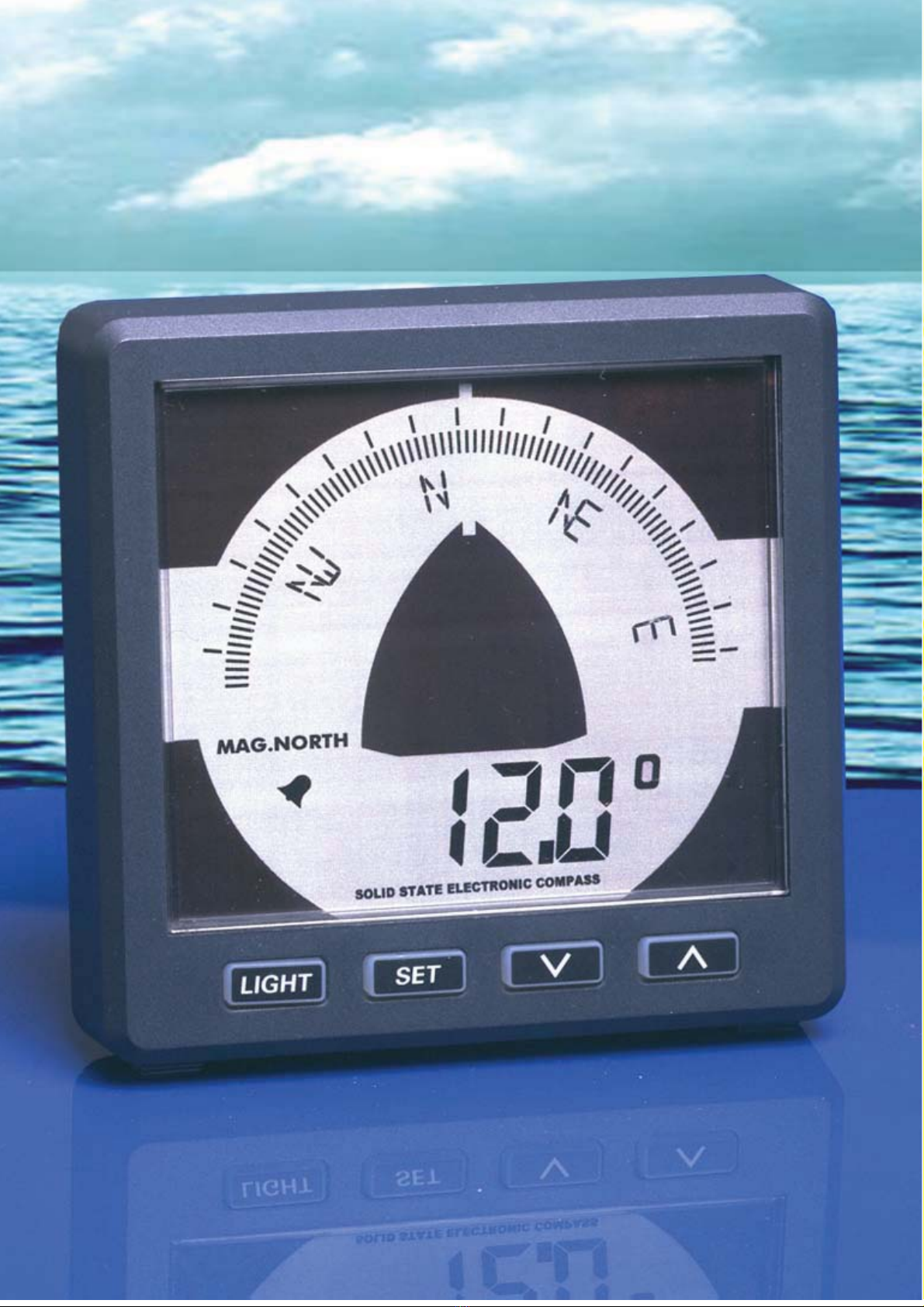
2.1 The display........................................................................................................ 2
2.2 Summary of operating functions ....................................................................... 2
2.2.1 Button sound .............................................................................................. 2
3 Operating................................................................................................................. 3
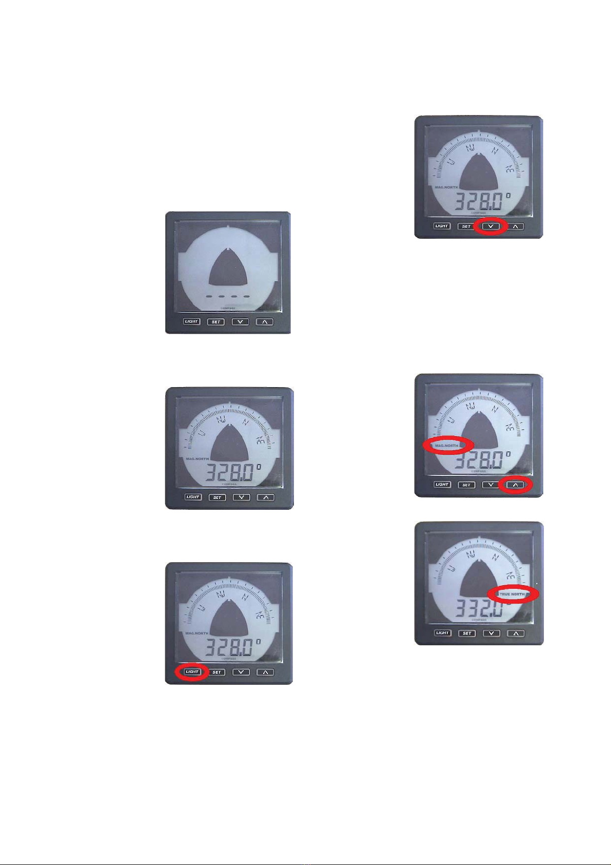
3.1 Switching on...................................................................................................... 3
3.2 Default view ...................................................................................................... 3
3.3 Backlight setting................................................................................................ 3
3.4 Off Course Alarm .............................................................................................. 3
3.5 Select magnetic or true north ............................................................................ 3
4 MENU...................................................................................................................... 4
4.1 Menu functions:................................................................................................. 4
4.1.1 Off course alarm (ST1) ............................................................................... 4
4.1.2 Damping (ST2) ........................................................................................... 4
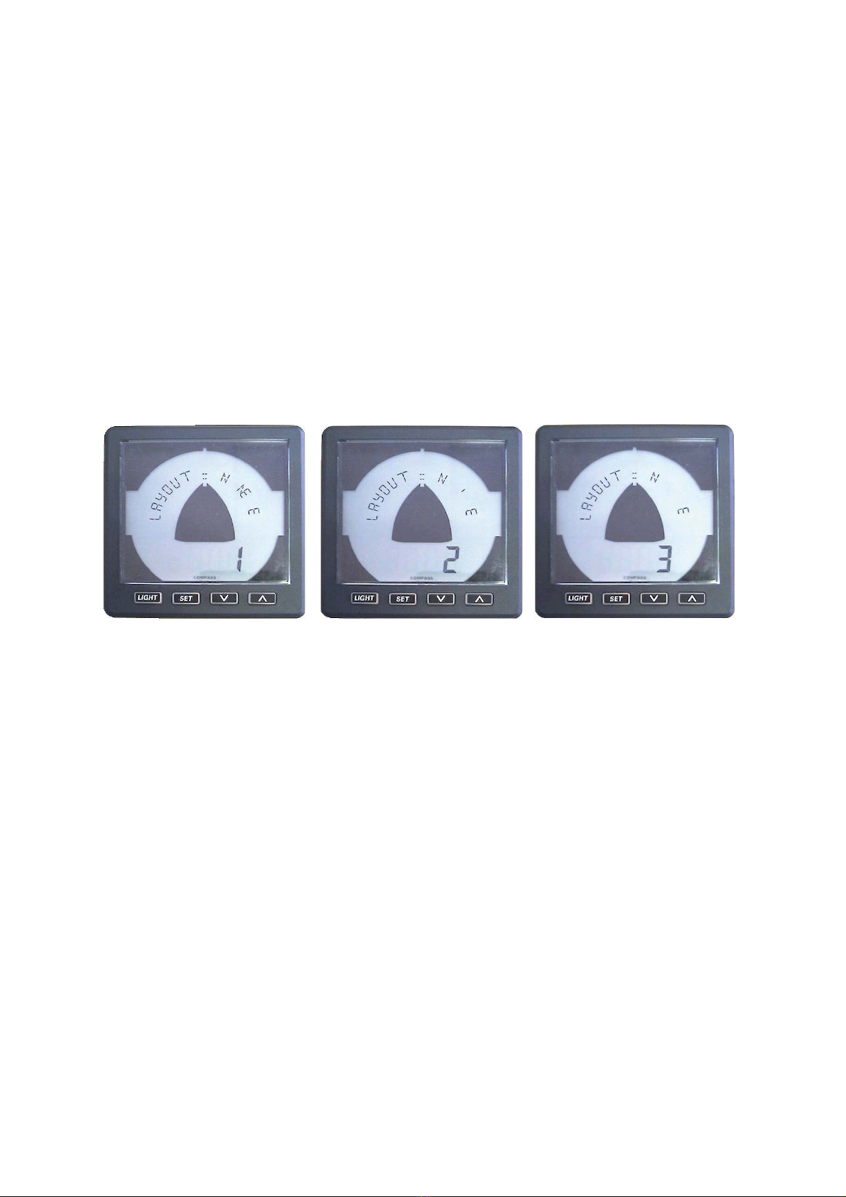
4.1.3 Layout (ST3)............................................................................................... 5
4.1.4 Key sound (ST4)......................................................................................... 5
4.1.5 Contrast (ST5)............................................................................................ 5
4.1.6 Calibration (ST6) ........................................................................................ 5
4.1.7 Align (ST7) ................................................................................................. 6
4.1.8 Variation (ST8) ........................................................................................... 6
4.1.9 Error messages .......................................................................................... 6
5 Installation ............................................................................................................... 7
5.1 Mechanical........................................................................................................ 7
5.2 Connections ...................................................................................................... 7
6 CD110 Specifications .............................................................................................. 7
6 CD110 Specifications .............................................................................................. 8
6.1 Hardware .......................................................................................................... 8
6.2 NMEA0183 messages ...................................................................................... 8
6.3 Bluetooth (optional)........................................................................................... 9
6.4 NMEA2000 (optional)........................................................................................ 9
6.5 Certifications ..................................................................................................... 9
7 Overall dimensions .................................................................................................. 9
7 Overall dimensions ................................................................................................ 10
7.1 Drill pattern...................................................................................................... 10
7.2 Outside dimensions......................................................................................... 10
8 Wiring diagrams..................................................................................................... 11
8.1 pin assignments .............................................................................................. 11
8.2 optional connections ....................................................................................... 11
8.2 optional connections ....................................................................................... 12
8.2.1 Backlight................................................................................................... 12
8.2.2 NMEA0183 echo ...................................................................................... 12
8.2.3 Alarm output ............................................................................................. 12
8.3 Service menu .................................................................................................. 12
8.3.1 Display info............................................................................................... 12
8.3.2 Compass info............................................................................................ 12
8.3.1 Display reset............................................................................................. 12
8.3.2 Compass reset ......................................................................................... 12
8.3.2 Close menu .............................................................................................. 12

1 Introduction
This manual contains information about the operation, calibration and installation of
the Compass Display ‘CD110’.
The following information can be read from the CD110 display:
x Heading on electronic compass rose
x Heading on 7 segment display
x True North or Magnetic North
x Damping
x Variation
x Alignment
x Off course alarm
1.1 Package contents
x CD110
x 2 female 6-pole connectors
x 1 female 4-pole connectors
x Mounting seal
x 4 metal rings+ M4 screwnuts
x Drill Template
x Quickstart instruction leaflet
Compass Display CD110 1

2 Working
2.1 The display
2.2 Summary of operating functions
Light Set Down Up
The unit has four control buttons. These buttons have the following functions:
x Light : press the LIGHT button one or more times to change the backlight
intensity or when in a menu this works as a reset button.
x Set : press the SET button to access the menu.
Use up/down keys to choose one of the menus and press SET to enter
the menu. If you press the SET button for more than 2 seconds you
will exit the menu.
x Down : on/off setting for the ‘off course alarm’ or when in a menu it works as a
button to select a menu or change settings.
x Up : select ‘true’ or ‘mag’ north, when in a menu it works as a button to
select a menu or change settings.
The function of a button is activated when the button is released, both UP and
DOWN buttons have an automatic repeat function. The buttons have a timeout of 1
minute.
2.2.1 Button sound
On the release of a button you will hear a key sound.
This sound can be switched offin the menu ‘Key Sound’ (ST4).
Compass Display CD110 2

3 Operating 3.4 Off Course Alarm
While in the
default view,
press the
down button to
switch the
alarm on or
off.
3.1 Switching on
The instrument must be switched on
with a separate switch (there is no
ON/OFF switch on the instrument
itself).
All segments
will be shown
for 2 seconds.
Then four
horizontal lines
are displayed
while the
display is
waiting for
compass data.
3.2 Default view
In the default
view the
current
compass
heading is
shown.
3.3 Backlight setting
The backlight has 7 settings:
x Level 1
x Level 2
x Level 3
x Level 4
x Level 5
x Remote
x Off
If the remote
setting is chosen the brightness of the
backlight will be set by a voltage
applied to the backlight pin on the
connector. See ‘Connections’ for pin
information.
Before you
can use the
alarm you have to set the values.
These have to be set by entering the
Course alarm menu (ST1).
If the alarm is on, the alarm indicator is
displayed.
3.5 Select magnetic or
true north
While in the
default view,
press the up
button to
choose
between mag.
(magnetic) or
true
(geographical)
north.
For true north indication, the variation
has to be set first. This can be done in
Variation menu (ST8).
Compass Indicator CD110 3

4 MENU
4.1 Menu functions:
To access the menu you have to press the SET button. Every time the Up/Down
button is pressed the next/previous menu item is shown, press SET to enter the
menu.
x Course alarm St 1
x Damping St 2
x Display layout St 3
x Key sound St 4
x Contrast St 5
x Calibration St 6
x Align compass St 7
x Variation St 8
x Close menu
4.1.1 Off course alarm (ST1)
The Off Course Alarm can be set for a certain course to steer by and a separate
boundary on both sides of the course. The buzzer inside the unit will beep when the
cours is out of the boundary.
x Press SET in the default view to enter the menu, press SET again to enter the
Course Alarm Menu (ST1).
Use the up/down buttons to set the preferred course.
x Press SET and enter the Portside alarm boundary with the up/down buttons.
This can be set from 2 to 45 degrees difference.
x Press SET and enter the Starboard alarm boundary with the up/down buttons.
This can be set from 2 to 45 degrees difference.
If the “Set course” is 246, the “Limit portside” set to 3 and the “Limit starboard” is set
to 2, then the alarm will sound if the course change is smaller than 246-3 = 243 and if
the course is higher than 246+2 = 248 degrees.
Use the down button in the default view to set the Alarm ON/OFF (see 3.4).
4.1.2 Damping (ST2)
Damping allows the user to change the damping level as conditions change. The
damping controls the averaging period over which the heading is displayed. Damping
does not make the compass less accurate, only slower. Damping levels can be set
from Off and 1 up to 7. In normal conditions level 2 is used.
x Press SET in the default view to enter menu. Press the up/down buttons to
select the Damping menu (ST2), press SET to enter the Damping menu.
Use the up/down buttons to change the value.
x Press SET short to enter the selected value or
x Press the Light button to reset the value to default (2) or
x Keep SET pressed for two seconds to exit to the default view.
Compass Display CD110 4

4.1.3 Layout (ST3)
There are three different layouts for the compass rose.
x Press SET in the default view to enter the menu. Press the up/down buttons to
select the Layout menu (ST3), press SET to enter the Layout menu.
x Use the up/down buttons to select a layout. A part of the selected layout is
shown in the compass rose text field.
x Press SET short to enter the selected value or
x Press the Light button to reset the value to default (1) or
x Keep SET pressed for two seconds to exit to the default view.
Example: press SET -> ST1 Course alarm
press up 2X -> ST3 Display Layout
press SET -> Layout 1= N NE E
press Up/Down -> Layout 2= N | E
press SET 2 seconds -> Default Display (1)
Layout 1 Layout 2 Layout 3
4.1.4 Key sound (ST4)
Press SET and use the up button to select the ST4 menu. Press SET to enter the
menu and now you can choose ON or OFF by pressing the up/down buttons.
x Press SET short to enter the selected value or
x Press the Light button to reset the value to default (ON) or
x Keep SET pressed for two seconds to exit to the default view.
4.1.5 Contrast (ST5)
Press SET and use the up button to select the ST5 menu. Press SET to enter the
menu and now you can choose a value between 0 to 9 by pressing the up/down
buttons.
x Press SET short and press the up/down buttons to select a contrast.
x Press the Light button to reset the value to default (0) or
x Keep SET pressed for two seconds to exit to the default view.
4.1.6 Calibration (ST6)
This Calibration menu can only be used in combination with the LCS, ECS1 or ECS3
compass.
Press SET and use the up button to select the ST6 menu. Press SET to enter the
menu and now you can choose Auto or Manual by pressing the up/down buttons.
Compass Display CD110 5

4.1.6.1 Automatic calibration
Function not used
You can switch this function OFF and use the manual calibration command.
4.1.7 Align (ST7)
Alignment error adjustment should be done by taking a couple of known runs from a
chart and compare the magnetic heading with the mag. heading shown on the
display. The difference can be compensated by setting the Align value.
x Press SET and up/down to select the Align menu (ST7). Press SET to enter
the menu. Use the up/down buttons to set the offset. This can be set in steps
of 0.1° up to +/- 99°.
To exit the menu press SET once or keep SET pressed for two seconds to exit to the
default view.
4.1.8 Variation (ST8)
The Variation can be set to compensate the magnetic heading so that the display
shows the geograpical (True) heading.
x Press SET and up/down to select the Variation menu (ST8). Press SET to
enter the menu. Use the up/down buttons to set the offset. This can be set in
steps of 0.1° up to +/- 45°.
To exit the menu press SET once or keep SET pressed for two seconds to exit to the
default view.
4.1.9 Error messages
No data input : The CD110 has not received data for more than 5 seconds,
Please check the connections
No response : No response after send a command:
x Check the connections or another not fully compatible
compass is connected.
Compass Display CD110 6

5 Installation
5.1 Mechanical
For dimension see chapter 7.
Using the template provided, cut out openings
in the instrument panel or bulkhead. Attach
the meter using the 4 threaded rods and nuts
provided.
Ensure that the seal fits correctly
between the meter and the panel or bulkhead.
5.2 Connections
For wiring diagram see chapter 8.
Connect the cable from the
compass sensor as
shown in the diagram. If you need
to cut and rejoin the cable be sure
to connect colour to colour.
The CD110 display is suitable for
both 12 and 24 Volt DC.
Connect the power supply as per
diagram.
See chapter 8 for the optional
connections.
Compass Display CD110 7

6 CD110 Specifications
6.1 Hardware
Resolution 0.5 deg.
Adjustable backlight : 5 brightness levels, off and external input
Reverse battery protection
Interface options :
x NMEA 0183 (Standard)
x NMEA 2000 (Optional)
x Bluetooth (Class 1)
The interface options are not user installable.
Power supply : 40mA @ 12V, 20mA @ 24V
Backlight current max. : 40mA (extra)
Bluetooth current max. : 100mA (extra)
NMEA2000 current max. : 100mA (extra)
Operating temp. range : -20 to +70 °C
Dimensions : 110 x 110 x (24,5 + 31,5mm)
Weatherproof Sealed: according to IP66
Alarm Output: Open collector, max. 100mA
6.2 NMEA0183 messages
The CD110 uses standard NMEA0183 messages but also some special calibration
commands and messages.
Receive standard message:
$HCHDG,X.X,Y.Y,v,Z.Z,Q*CC<13><10>
X.X = compass heading
Y.Y,v = not used
Z.Z = variation
Q = variation available (a) or invalid (v)
CC = Checksum field
<13> = carriage return
<10> = line feed
Checksum = The checksum is the last field in a message and follows the checksum
delimiter character “*”. The checksum is the 8-bit exclusive OR (no start or stop bits)
of all characters in the message, including “,” delimiters, between but not including
the “$” and the “*” delimiters.
Special commands:
$IIELP,CAL,ECS,STRT*CC<13><10> // Start calibration command
$IIELP,CAL,ECS,STOP*CC<13><10> // Stop calibration command
$IIELP,CAL,ECS,AUTO*CC<13><10> // Auto calibration command
$IIELP,CAL,ECS,MANU*CC<13><10> // Disable auto calibration command
$IIELP,CAL,ECS,VARI,X.X*CC<13><10 // Variation value command
$IIELP,CAL,ECS,ALIG,X.X*CC<13><10 // Align value command
$IIELP,CAL,ECS,SFWR*CC<13><10 // Software version command
Compass Display CD110 8

Response message:
$IIELP,CAL,ECS,DONE*CC<13><10> // message “Done”
$IIELP,CAL,ECS,FAST*CC<13><10> // message “Fast”
$IIELP,CAL,ECS,SLOW*CC<13><10> // message “Slow”
$IIELP,CAL,ECS,STRT*CC<13><10> // message “Start”
$IIELP,CAL,ECS,STOP*CC<13><10> // message “Stop”
$IIELP,CAL,ECS,SFWR,X.X,Y,Z*CC<13><10> // X.X: Software version.
Y:1=ECS1; 2=ECS2; 3=ECS3; 4=LCS
Z: 1=NMEA0183;
2=NMEA2000
3=Bluetooth
6.3 Bluetooth (optional)
Class-1 complient: Up to 100 meter range (free field)
Antenna: Integrated
Carrier frequency : 2402Mhz to 2480Mhz
Output power: 14dBm typ.
Messages: NMEA0183 format (see 7.2)
6.4 NMEA2000 (optional)
Update rate : 10 cycles per second
PGN 126208 : Request/ Command/ Acknowledgment Group function
PGN 59392 : Acknowledgment
PGN 59904 : Request
PGN 60160 : Transport Protocol, Data Transfer
PGN 60416 : Transport Protocol, Connection Management
PGN 60928 : Address Claim
PGN 126996 : Product information
PGN 126464 : Transmit/ Receive PGN List Group Function
PGN 127250 : 1. SID Sequence ID INT8 unsigned
2. Heading Sensor Reading INT16 unsigned
3. Deviation INT16 signed Not used
4. Variation INT16 unsigned
5. Heading sensor reference 2 bits 0=True
1=Magnetic
2=Error
3=Null
6. Reserved bits variable
6.5 Certifications
Maritime Navigational and Radiocommunication
Equipment & Systems : according to IEC 60945
EMC : Conducted/Radiated Emmission : according to IEC 60945-9
Conducted/Radiated Immunity : according to IEC 60945-10
Safety : Dangerous voltage, etc. : according to IEC 60945-12
Compass Display CD110 9

7 Overall dimensions
7.1 Drill pattern
(included on separate sheet)
7.2 Outside dimensions
Compass Display CD110 10

8 Wiring diagrams
8.1 pin assignments
1 GND shield
2 Backlight dim input (0 to 12V or 0 to 24V, autosense)
3 NMEA2000-2 (optional)
4 NMEA2000-1 (optional)
5 GND
6 +12V/+24V Compass power output
7 GND
8 NMEA0183 echo of NMEA input (pin 15 and 16)
9 Not used
10 +12V/+24V Battery power input (use power switch and 500mA fuse)
11 Battery GND
12 Alarm output (max. 100mA open collector)
13 NMEA0183-gnd
14 NMEA0183-out
15 NMEA0183-INA
16 NMEA0183-INB
OUTPUT
INPUT
1 2 3 4 5 6 7 8 9 10 11 12 13 14 15 16
+-
NMEA in -
NMEA in +
SHIELD
Backlight
Dim input (+)
fuse
12 / 24 V
Compass Display CD110 11

Compass Display CD110 12
8.2 optional connections
8.2.1 Backlight
The backlight input is an autosense input which means that the applied voltage is relative to the
battery voltage. If the battery voltage is 12V the backlight setting is maximum when the applied voltage
to pin 2 is 12V. If the battery voltage is 24V and the applied voltage to pin 2 is 12V the brightness will
be dimmed.
PIN 2 Backlight dim input (0 to 12V or 0 to 24V, autosense)
8.2.2 NMEA0183 echo
The NMEA echo pin is used for connecting other devices who also need the NMEA messages from
the compass sensor.
PIN 8 NMEA0183 output, in combination with GND pin 7
8.2.3 Alarm output
The Alarm output is used for connecting an external warning device such as a buzzer. If more than
100 mA is needed a small relay should be used.
PIN 12 Alarm output, in combination with the battery + pin
8.3 Service menu
To enter the service menu you have to press SET when you switch the power on.
8.3.1 Display info
Press set to view: Display type, interface, software version.
8.3.2 Compass info
Press set to view: Compass type, interface, software version.
8.3.1 Display reset
Press SET to reset the display to factory settings.
8.3.2 Compass reset
Press SET to reset the compass to factory settings.
8.3.2 Close menu
To exit the service menu press SET.

Table of contents
Popular Marine Equipment manuals by other brands

Vixen Horns
Vixen Horns VXS-9080SCL installation guide

Kenwood
Kenwood KMR-330 instruction manual

INIM Electronics
INIM Electronics enea ES2050 quick start guide

Aquatic
Aquatic CP6 User & installation manual

COBHAM
COBHAM SAILOR 6110 mini-C GMDSS installation manual

Kongsberg
Kongsberg cPAP MKII Quick reference guide