Ninglu DS207 User manual
7
N
O
p
-in
c
N
av
i
p
erati
c
h
D
i
ga
t
D
on
&
D
u
a
t
io
n
D
S
2
&
Inst
a
a
l-c
n
S
o
2
07
a
llati
o
Docume
n
Edition:
ha
n
o
u
n
o
n M
a
n
t: NLT-D
S
V1308
2
n
n
e
n
de
r
anu
a
S
207-SSE
N
2
2
e
l
r
a
l
N

1
Contents
Working Principle......................................................................................... 2
Working Principle of the Sounder........................................................... 2
Screen Display.......................................................................................... 2
Introduction .................................................................................................. 3
Screen........................................................................................................ 3
Operation ...................................................................................................... 4
Operation ...................................................................................................... 5
Installation .................................................................................................... 6
Host installation........................................................................................ 6
Operator unit............................................................................................. 6
1. Table ................................................................................................ 6
2. Hung ................................................................................................ 6
Installation .................................................................................................... 7
3. Flush................................................................................................ 7
Transducer installation ............................................................................ 7
Installation .................................................................................................... 8
Connection................................................................................................ 8
Specification................................................................................................. 9
2
Working Principle
Working Principle of the Sounder
Screen Display
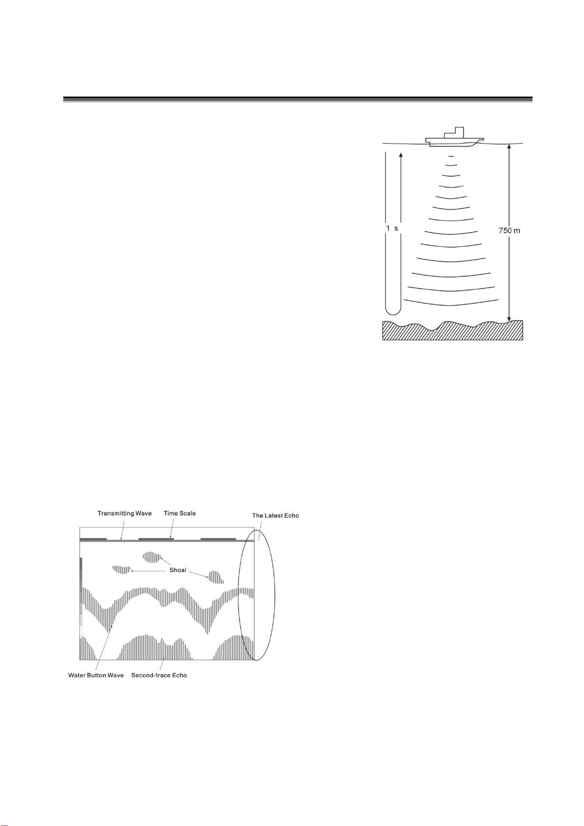
The ultrasonic wave is sent and received repeatedly by the sounder. The latest echo
is recorded as a line on the far right of the screen. The image is consisting of the
moving-to- left echo.
The acoustic velocity is 340m/s in the air and 1,500m/s
in the water. The acoustic time is one second during the
round-trip distance of the underwater 750m. So, the
target depth can be calculated by measuring the
round-trip time of acoustic wave (Fig. 1).
Due to ultrasonic frequency is higher than that of the
sound waves by human-ear hearing, ultrasonic is
suitable for underwater detection. The ultrasonic
transducer of the sounder can launch and receives the
ultrasonic wave. Through recording, the underwater
target is displayed on the LCD screen and the water
depth is calculated for display.
The discontinuous yellow line is the
time scale of 30 seconds. Under the
time scale, the horizontal line is the
transmitting wave. Shown in Fig. 2, the
three spot may be the shoal. Under shoal,
there are the water-button wave and
second-trace echo, which depth is the
twice of the water-button wave depth. The
water button is harder, the echo is
stronger and thicker.
Fig. 1
Fig. 2
3
Introduction
DS207 dual-channel echo sounder is of high sensitivity and advanced detecting
software which can display the water bottom landform, depth and figures
accurately. With 7 inch color TFT LCD screen of high resolution (480X234 Pixel),
it is easily operated and used for ship navigation.
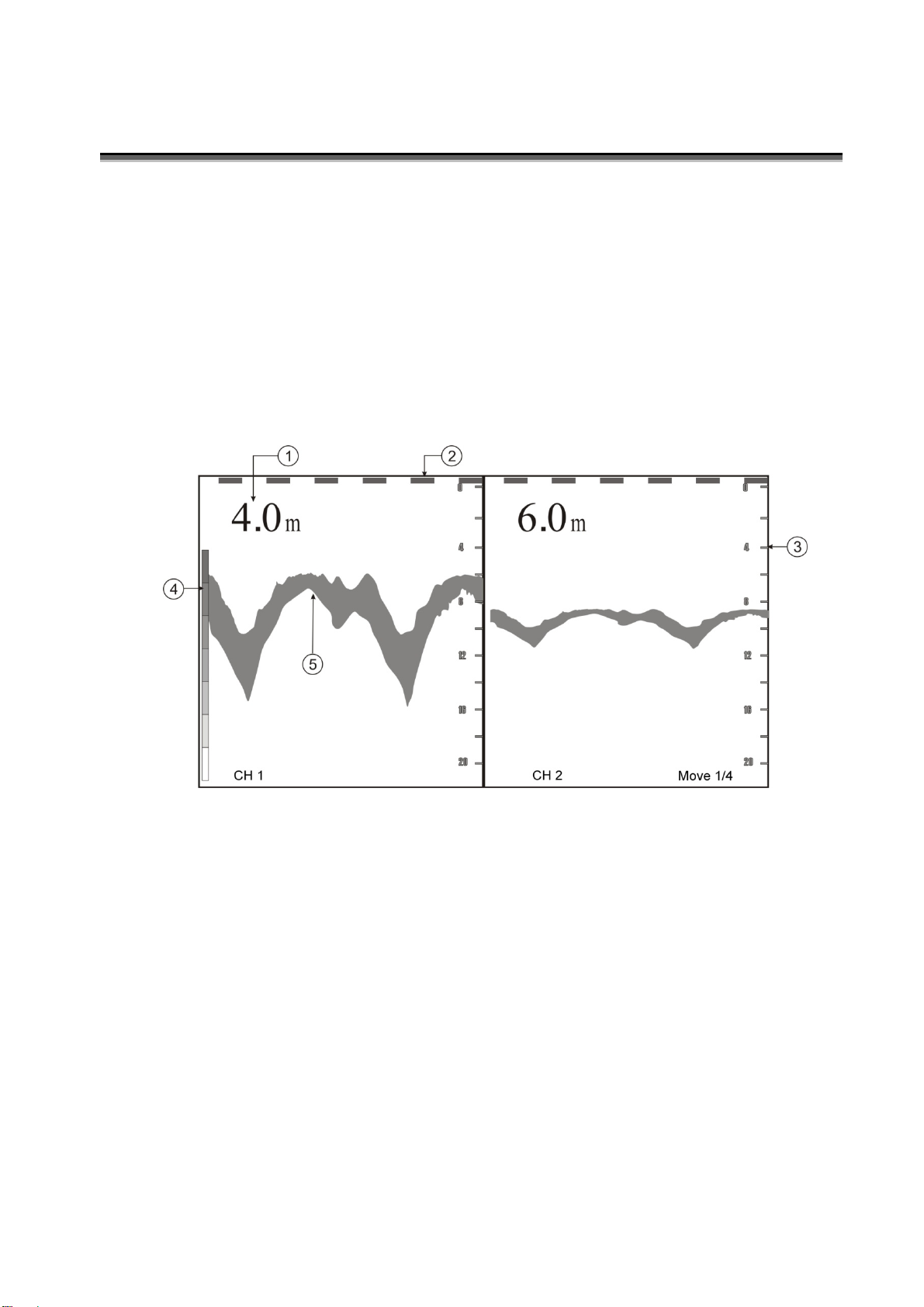
Screen
①Depth ②Time scale ③Basic range ④Echo Level ⑤Echo
4
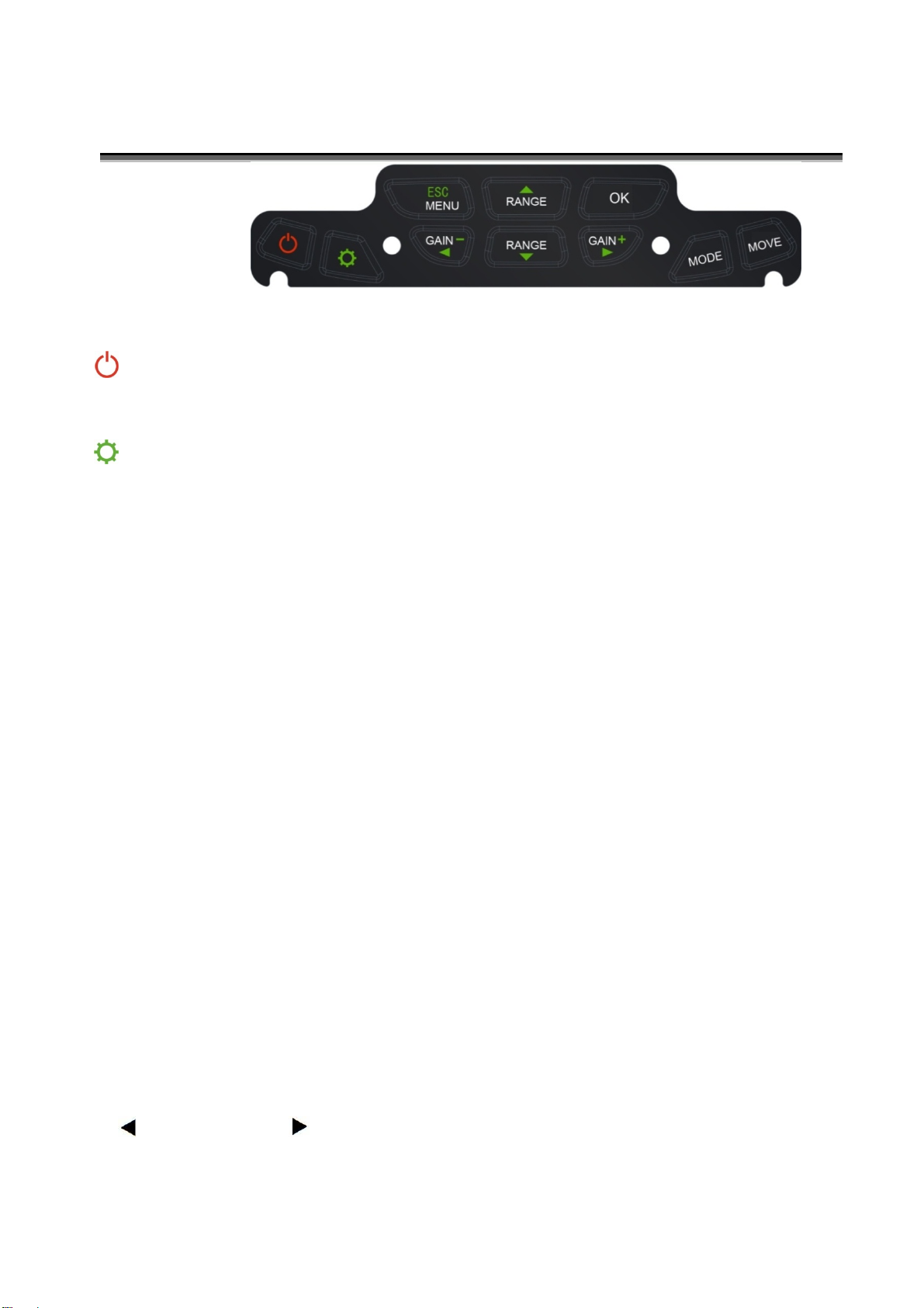
Operation
Keyboard
Power ON/OFF
Switch on/off the power supply
Brightness
Adjust the LCD brightness (LCD backlight)
GAIN
【Gain+】&【Gain-】
In single channel model,set gain by pressing【Gain+】&【Gain-】directly.
In dual channel model, using 【Menu】to adjust gain value.
RANGE
【Range▲】&【Range▼】
Press【Range▲】&【Range▼】directly to adjust basic depth range, while the Auto range is
off (set in Menu).
MODE
Press【MODE】repeatedly to choose among three display model: Channel 1, Channel 2,
Dual-channel.
MOVE
The picture speed function is to set the screen frame rolling speed based on per ping of
transmission. Press【MOVE】repeatedly to choose among speed:1/4、1/2、1/1、2/1、4/1.
MENU
Press【Menu】into menu.
【▲】:UP 【▼】: DOWN
【▲】: LEFT 【- 】: RIGHT

5
Operation
GAIN_1 Gain for channel 1:01-20
GAIN_2 Gain for channel 2:01-20
ALARM Set alarm depth: OFF/0.4-10m
BUZZER Turn on/off the alarm buzzer
LEVEL Set echo colors: 3-8
AUTO Auto range:OFF, Track 1 (channel 1), Track 2 (channel 2)
When auto range is on, range cannot be adjusted manually.
POWER Power output:BIG/SMALL
ColorSet Set background color:Blue/Black
PUSH[OK]
EXIT Save all setting and quit form menu
6
Installation
Host installation
The host installation can be in the type of Hung、Table and Flush.
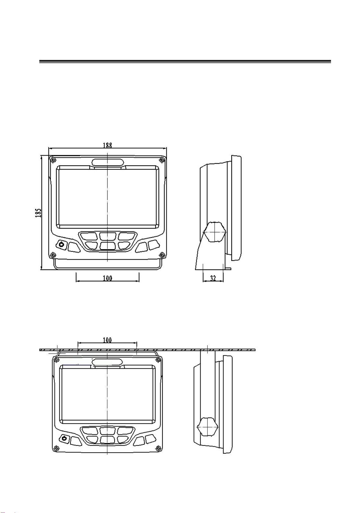
Operator unit
1. Table
2. Hung
Unit: mm
Screws location Screws location

7
Installation
3. Flush
Transducer installation
Single transducer is normally installed in the fore-ship. Larger Vessels are
often fitted with two transducers, one fore and one aft, select with an optional
transducer selector. Optimal system operation is achieved by fitting the
transducer as deep as possible on the hull. The transmitting surface of the
transducer must be installed horizontal. On vessels with a deep keel, if the
transducer must be fitted higher than the keel, it should be fitted towards the
side, as far from the keel as possible to avoid false keel echoes.
Do not mount transducers close to the propeller or aft of other hull
installations (outlets, vents or other protruding details). It is of course necessary
to select a part of the hull that is submerged under all load and speed conditions,
and to avoid positions where air is trapped in heavy weather. If a flat, horizontal
section is not available for transducer fitting, the shipyard must construct a
suitable bed. Do not paint the surface.

8
Installation
Connection

9
Specification
Item Specification
Display 7 inch TFT LCD,480×234 pixel
Frequency Dual-channel 200kHz
Range 2.5-200m
Accuracy The higher value between ±1% of the range
and ±0.1m
Resolution 0.1m
Min. depth
detectable
0.3m
Auto range Yes
Depth output NMEA0183
Output power 200kHz, 300W
Time scale On screen 30s time scale
Echo Levels 8 colors signal levels
Alarm Types Shallow
Alarm Beeper Buzzer(switch able),flashing
Power supply DC24V(19~33V), 20W
Temperature 0~50℃,IEC 60945
Water proof IP52,IEC 60529
Table of contents
Other Ninglu Marine Equipment manuals


