product designed for industrial use – keep out of the reach of children –
PN.500
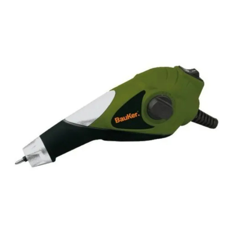
Engraving Stylus
INSTRUCTIONS INCLUDING
Types of use, recommendations for use, set-up, the work station,
safety instructions, instructions for disassembly, re-assembly and
maintenance.
IMPORTANT
These instructions must be read and fully understood prior to any
set-up, use, maintenance or repair. Keep them handy in a safe
place.
FEATURES
Description: engraving stylus
Reference: PN.500
Weight: 0.25 kg
Supplied with a 0.35 radius carbide tip.
Carbide tips available: 0.20 mm, 0.35 mm, 0.50 mm
NOISE LEVEL
72 dB(A)
Test method: average sound pressure at four points 90° at a radius
of 1 m around the source (measured in a vacuum).
VIBRATION LEVEL
11.7 m persec²
Test method: ISO 8662-1 (NFE 90-320).
RECOMMENDATIONS
Balancer / support
Safety glasses
Safety gloves
Dust mask
Hearing protection
Recommended pressure: 6 bars
Minimum air pressure: 5 bars
Maximum air pressure: 7 bars
Internal diameter of supply hose: 5 mm
Maximum length of supply hose: 10 m
WORK STATION
The work station must be clean and the floor must have good
adhesion. The toll may only be used as a hand tool and for the use
for which it was intended
INTENDED USE
Engraving on metal (steel, cast iron, aluminium, etc.). Do not use on
carbide parts.
Do not use for other work without checking with the manufacturer or
an approved dealer.
SET-UP
Use clean, lubricated air, regulated to a pressure of 6 bars. Follow
the recommendations given (hose, safe pressure, etc.). Provide a
lubricating regulator filter on the supply line and a shut-off valve that
can be accessed and operated easily. In the lubricator, use an oil
especially designed for pneumatic tools. Set the lubricator for a rate
of one drop per minute.
After initial use, directly insert a small quantity (3 ml) of pneumatic
tool oil into the hose and run the tool at no load. Repeat, if
necessary.
USE
Turn the ring (ref. 2) to start the vibration. Adjust the position of the
ring for the optimum tip vibration (ref 17). Put the tip in contact with
the surface to be marked and do the desired marking or drawing by
slowly moving the tool. The engraving stylus must not be inclined by
more than 15° from the vertical from the work piece surface.
Changing the tip: undo the front casing (ref 3), remove the tip (ref
17), the spring (ref 12) and remove the seal (ref 10). Check the
condition of the seal (ref 10) and the spring (ref 12); change, if
necessary. Place the seal (ref 10) on the new tip. Position the tip
and the spring (ref12) inside the casing (ref 3). Screw the cover (ref
3) firmly in place.
MAINTENANCE
The important points about maintaining this tool are as follows:
- Keep it clean. From time to time, check the condition of
the compressed air connections, the correct operation of
the inlet adjustment (ref 2) and the condition of the
marking tip (ref 17).
- Check that the set-up instructions are followed (clean,
lubricated air, suitable oil, pressure between 5 and 7 bars).
- If the stylus remains unused for a long period, pour a
small quantity (3 ml) of pneumatic tool oil directly into the
supply hose, then run the tool for 2 or 3 seconds to
distribute a film of oil.
DISASSEMBLY INSTRUCTIONS
ensure that the air supply is disconnected. Carefully study the
exploded view attached, before starting to disassemble the product;
collect the parts in a clean container of sufficient size.
Take care with the direction of the threads: left–handed threads are
identified by the letter G in the exploded view.
INSTRUCTIONS FOR RE-ASSEMBLY
Carefully clean each piece and check the extent of wear. Replace
worn parts only with original parts. Re-assemble in the reverse
order, lubricating each part with air tool oil. Check that each moving
part operates correctly.
LA-CO Industries Inc. 1201 Pratt Boulevard, Elk Grove Village, IL 60007-5746 USA
LA-CO Industries Europe S.A.S., Allée des Combes PI de la Plaine de l’Ain 01150 BLYES France


