manuals.online logo
Brands
  1. Home
  2. •
  3. Brands
  4. •
  5. Epilog Laser
  6. •
  7. Engraver
  8. •
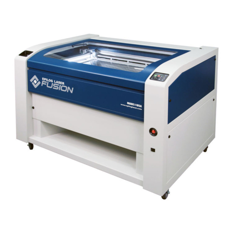
  9. Epilog Laser Fusion User manual

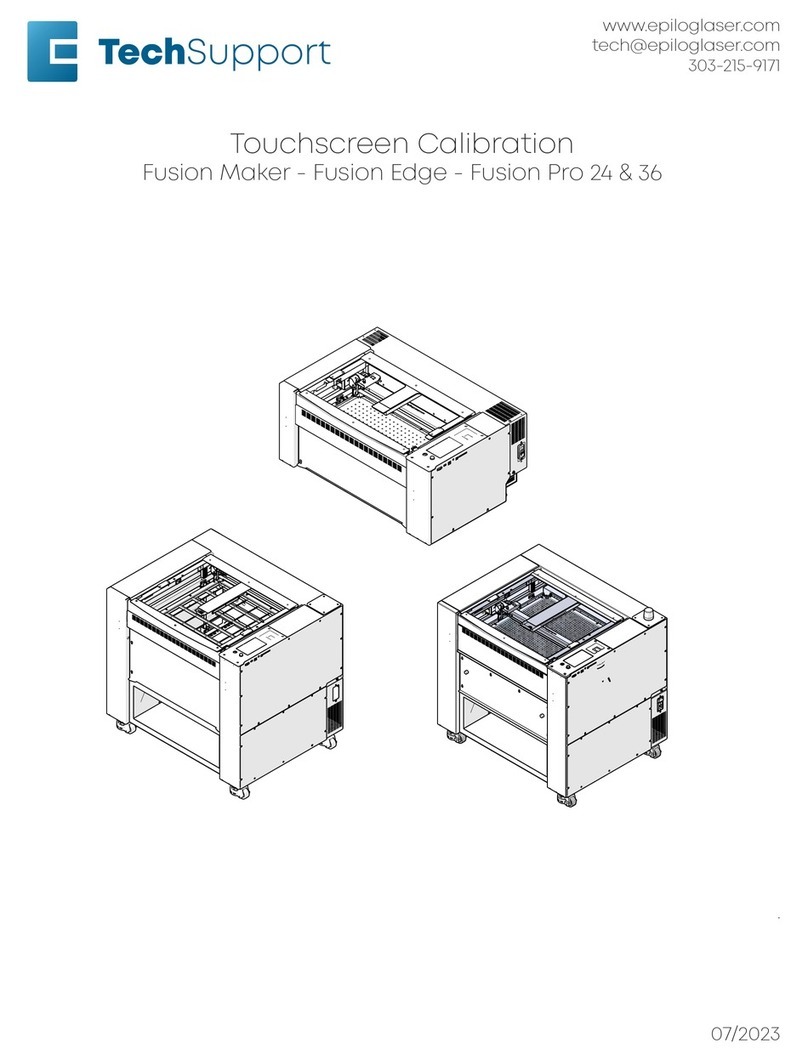
Epilog Laser Fusion User manual

www.epiloglaser.com
tech@epiloglaser.com
303-215-9171
CO2 Laser Alignment
Fusion Maker - Fusion Edge - Fusion Pro 24 & 36
Parts Required Tools/ Materials Required
• LC0397 - Holder, Target, Alignment • 5/32” Allen Wrench
• 3/32” Allen Wrench
• Masking Tape
• Eyeglasses or protective eyewear
.
07/2023
17000 - CO2 Laser Alignment
2
CO2 Laser Alignment
CO2 laser alignment should be checked
periodically to ensure that the engraver is
operating at optimum peormance.
Complete this procedure if any of the
following behaviors are observed:
• Laser power appears weak in certain
areas of the table, especially when
moving from le to right in the
engraver
• The engraver is unable to eectively
cut through materials at or around the
recommended settings.
• Optics in the lens assembly fail
prematurely.
• If the engraver has been moved to a
new location.
Or if any of these components have been
replaced:
• Laser tube
• Mirror #1, #2, or #3
• X-axis assembly
• Red dot diode
CO2 Laser Safety
The laser assembly used in the Fusion Pro
CO2 engraver can cause serious and or
permanent injury if safety procedures are
not observed.
Do not fire the CO2 laser with any of the
engraver panels removed.
Do not place any part of your body in the
beam path while the laser is in operation.
Do not defeat the safety interlock system
in the engraver.
It is recommended that eye protection
such prescription eyeglasses, Lexan, or
other polycarbonate safety glasses be
worn by all those present for the duration
of the laser alignment procedure.
!
!
17000 - CO2 Laser Alignment
3
The CO2 laser alignment consists of three
(3) parts:
• Pre-alignment to ensure that the CO2
laser and red dot diode are coaxial.
• Cutting laser alignment.
• Perpendicular alignment
Pre-Alignment
1. Turn on the engraver, and let it
complete the startup process.
2. Install the laser alignment target over
the window optic on the le side of
the lens carriage and place a piece of
masking tape over the target:
3. Press the Gear icon on the display to
enter the Settings menu:
4. Press the Alignment button to enter
the Alignment Mode menu:
The Alignment Mode menu allows you to
move the lens carriage to specific table
position and fire the laser without the
need to send a job to the engraver.
5. Ensure that the laser power is set to
10% and press the Activate button
once to fire the laser.
6. Look through the top door, or open the
top door if needed, and observe if the
laser marked the masking tape.
7. If the laser did not mark the tape,
close the top door and press and hold
the Activate button while observing
the masking tape on the alignment
target. As soon as you observe the
laser marking the tape, let go of the
Activate button.
In certain situations the CO2 laser
alignment may be very poor, preventing
you from getting a burn mark in position
4. If this is the case, attempt to get a burn
mark in position 1.
8. Once a burn mark is observed on
masking tape, press the Red Dot
Pointer button to turn on the red dot:
17000 - CO2 Laser Alignment
4
1. Inspect the location of the red dot in
relation to the burn mark le by the
laser.
If additional viewing space is needed to
observe the alignment target, the y-axis
bellows can be disconnected from the
x-axis assembly.
2. For an accurate alignment, both the
red dot and burn mark should appear
in the same exact location on the
tape.
3. If both the red dot and burn mark
appear in the same exact location on
the tape, move to the next section of
the alignment procedure.
At this point in the alignment procedure,
the goal is that the red dot and burn
mark are aligned with each other. The
position of the red dot and burn mark in
relation to the center of the alignment
target is not important.
4. If both the red dot and burn mark do
not appear in the same exact location
on the tape, remove the lower rear
panel of the engraver and locate the
red dot diode to the right side of the
laser tube:
Adjusting the Red Dot
1. Adjust the red dot so that it is
centered over the burn mark on the
masking tape made by the laser using
the three (3) Allen adjustment screws:
2. Once the red dot and burn mark
appear in the same exact spot, install
the lower rear panel of the engraver
and move to the Cutting Laser
Alignment procedure
Cutting Laser Alignment
It is very important that the laser and the
red dot are coaxial prior to beginning this
process. You will not be able to properly
align the laser if the red dot and the
cutting laser are not coaxial.
For alignment purposes, the table of the
engraver is separated into four (4)
quadrants or table positions. The
location of each quadrant or position is
determined by the relative distance from
the laser.
17000 - CO2 Laser Alignment
5
Table Positions
There are four (4) mirrors in the Fusion Pro
CO2-only engraver, all of which may need
to be adjusted while aligning the cutting
laser.
Each of the mirrors in the Fusion Pro
engraver are referenced by number in
this procedure and correspond to a
specific table location. When adjusting
a mirror, ensure that the correct one is
being adjusted for that specific table
location.
Mirror Locations, Numbers, and
Corresponding Table Position
Mirror 1 / Position 1
Mirror 2 / Position 2
Mirror 3 / Positions 3 & 4
Mirror 4/Perpendicular Alignment
17000 - CO2 Laser Alignment
6
1. Inspect the location of the red dot in
relation to the burn mark le by the
laser.
If additional viewing space is needed to
observe the alignment target, the y-axis
bellows can be disconnected from the
x-axis assembly.
2. For an accurate alignment, both the
red dot and burn mark should appear
in the same exact location on the
tape.
3. If both the red dot and burn mark
appear in the same exact location on
the tape, move to the next section of
the alignment procedure.
At this point in the alignment procedure,
the goal is that the red dot and burn
mark are aligned with each other. The
position of the red dot and burn mark in
relation to the center of the alignment
target is not important.
4. If both the red dot and burn mark do
not appear in the same exact location
on the tape, remove the lower rear
panel of the engraver and locate the
red dot diode to the right side of the
laser tube:
Adjusting the Red Dot
1. Adjust the red dot so that it is
centered over the burn mark on the
masking tape made by the laser using
the three (3) Allen adjustment screws:
2. Once the red dot and burn mark
appear in the same exact spot, install
the lower rear panel of the engraver
and move to the Cutting Laser
Alignment procedure
Cutting Laser Alignment
It is very important that the laser and the
red dot are coaxial prior to beginning this
process. You will not be able to properly
align the laser if the red dot and the
cutting laser are not coaxial.
For alignment purposes, the table of the
engraver is separated into four (4)
quadrants or table positions. The
location of each quadrant or position is
determined by the relative distance from
the laser.
17000 - CO2 Laser Alignment
7
Table Positions
There are four (4) mirrors in the Fusion Pro
CO2-only engraver, all of which may need
to be adjusted while aligning the cutting
laser.
Each of the mirrors in the Fusion Pro
engraver are referenced by number in
this procedure and correspond to a
specific table location. When adjusting
a mirror, ensure that the correct one is
being adjusted for that specific table
location.
Mirror Locations, Numbers, and
Corresponding Table Position
Mirror 1 / Position 1
Mirror 2 / Position 2
Mirror 3 / Positions 3 & 4
Mirror 4/Perpendicular Alignment
17000 - CO2 Laser Alignment
8
Adjusting Mirror/Position 1
1. Place a new piece of masking tape on
the alignment target.
2. Ensure that the red dot pointer is
activated.
3. In Alignment Mode, press Top Le to
move the lens carriage to the top le
corner (position 1) of the engraver.
4. Inspect the location of the red dot in
relation to the center of the alignment
target. If the red dot pointer is not in
the center of the alignment target,
adjustments will need to be made to
mirror 1.
5. Remove the lower mirror cover at the
back le corner of the engraver:
6. Adjust the red dot position so it is
centered on the alignment target
using the three (3) Allen adjustment
screws located on the back of mirror 1:
Mirror 1 Adjustment Screw Guide
Adjusting Mirror/Position 2
1. Ensure that the red dot pointer is
activated.
2. In Alignment Mode, press Bottom
Le to move the lens carriage to the
bottom le corner (position 2) of the
engraver.
3. Inspect the location of the red dot in
relation to the center of the alignment
target. If the red dot pointer is not in
the center of the alignment target,
adjustments will need to be made to
mirror 2.
17000 - CO2 Laser Alignment
9
4. Remove the upper mirror cover at the
back le corner of the engraver:
5. Adjust the red dot position so it is
centered on the alignment target
using the three (3) Allen adjustment
screws located on the back of mirror 2:
Mirror 2 Adjustment Screw Guide
6. Once the red dot position is centered
on the alignment target, move the
carriage back to position 1.
7. If the red dot position is still centered
on the alignment target while the
lens carriage is in position 1, move to
Adjusting Mirror/Position 3.
8. If the red dot position is no longer
centered on the alignment target
while the lens carriage is in position 1
aer adjusting position 2, adjustments
to mirror/position 1 will need to be
made again.
9. Move between positions 1 and 2,
adjusting the respective mirror for
each position until the red dot is
centered on the alignment target at
both positions.
In some cases, this process can take
several back and forth movements be-
tween positions 1 and 2. Ensure that the
correct mirror is being adjusted for each
position.
Adjusting Mirror 3/Positions 3&4
1. Ensure that the red dot pointer is
activated.
2. In Alignment Mode, press Top Right to
move the lens carriage to the top right
corner (position 3) of the engraver.
3. Inspect the location of the red dot in
relation to the center of the alignment
target. If the red dot pointer is not in
the center of the alignment target,
adjustments will need to be made to
mirror 3.
17000 - CO2 Laser Alignment
10
4. Remove the le panel of the engraver.
5. Adjust the red dot position so it is
centered on the alignment target
using the three (3) Allen adjustment
screws located on the back of mirror 3:
Mirror 3 Adjustment Screw Guide
6. Once the red dot position is centered
on the alignment target, move the
carriage back to positions 1 and 2.
7. If the red dot position is still centered
on the alignment target while the lens
carriage is in positions 1 and 2, move
to the Perpendicular Alignment.
8. If the red dot position is no longer
centered on the alignment target
while the lens carriage is in positions
1 and or 2 aer making adjustments
to mirror/position 3, adjustments to
mirror/positions 1 or 2 will need to be
made again.
9. Move between positions 1, 2, and 3,
adjusting the respective mirror for
each position until the red dot is
centered on the alignment target at
all three positions.
In some cases, this process can take
several back and forth movements
between positions 1, 2, and 3. Ensure that
the correct mirror is being adjusted for
each position.
Perpendicular Alignment
Once the mirrors have been aligned, we
need to adjust for the perpendicularity of
the cut. By making these adjustments, we
can ensure that the vector cut is as close
to 90 degrees as possible.
This is a very important step for
customers who do a lot of cutting with
the machines.
Failure to verify the perpendicular
alignment can result in poor vector
peormance and premature failure of
the optics in the lens carriage.
1. Ensure that the red dot pointer is
activated.
2. Use the Focus menu to raise the table
up, stopping short of depressing the
autofocus plunger.
3. Remove the alignment target from
the lens carriage and place it on the
table, directly under the lens tube.
Move the target so the red dot is
centered on the alignment target.
Once here, place a piece of masking
tape over the target to ensure that it
does not move.
4. Using the Focus menu, lower the table
3-4” (75mm - 100mm).
17000 - CO2 Laser Alignment
11
5. Inspect the location of the red dot in
relation to the center of the alignment
target. If the red dot pointer is not in
the center of the alignment target,
adjustments will need to be made to
mirror 4:
6.
7.
8.
9.
10.
11.
12.
13.
14.
15.
16.
Mirror 4 Adjustment Guide
17. Adjust the red dot location so that it is
centered on the alignment target.
18. Raise the table while watching the
location of the red dot. If the red
dot moves o of the center of the
alignment target, repeat this process,
until there red dot does not change
position when raising or lowering the
table.
If further assistance is required, contact
Epilog Laser Technical Support by phone
at 303-215-9171, or by email at
tech@epiloglaser.com

Other manuals for Fusion

10

This manual suits for next models

3

Other Epilog Laser Engraver manuals

Epilog Laser Fusion User manual

Epilog Laser

Epilog Laser Fusion User manual

Epilog Laser Fusion User manual

Epilog Laser

Epilog Laser Fusion User manual

Epilog Laser Fusion Pro 32 User manual

Epilog Laser

Epilog Laser Fusion Pro 32 User manual

Epilog Laser Helix Installation and operation manual

Epilog Laser

Epilog Laser Helix Installation and operation manual

Epilog Laser FiberMark User manual

Epilog Laser

Epilog Laser FiberMark User manual

Epilog Laser Fusion User manual

Epilog Laser

Epilog Laser Fusion User manual

Epilog Laser FiberMark User manual

Epilog Laser

Epilog Laser FiberMark User manual

Epilog Laser MINI User manual

Epilog Laser

Epilog Laser MINI User manual

Epilog Laser MINI 18 User manual

Epilog Laser

Epilog Laser MINI 18 User manual

Epilog Laser Fusion Use and care manual

Epilog Laser

Epilog Laser Fusion Use and care manual

Epilog Laser MINI User manual

Epilog Laser

Epilog Laser MINI User manual

Epilog Laser FiberMark Fusion 13000 User manual

Epilog Laser

Epilog Laser FiberMark Fusion 13000 User manual

Epilog Laser Edge 12 User manual

Epilog Laser

Epilog Laser Edge 12 User manual

Epilog Laser Zing User manual

Epilog Laser

Epilog Laser Zing User manual
Epilog Laser Fusion Pro 32 User manual
Epilog Laser

Epilog Laser Fusion Pro 32 User manual

Epilog Laser Fusion M2 32 User manual

Epilog Laser

Epilog Laser Fusion M2 32 User manual

Epilog Laser Zing User manual

Epilog Laser

Epilog Laser Zing User manual

Epilog Laser Fusion Pro 32 User manual

Epilog Laser

Epilog Laser Fusion Pro 32 User manual

Epilog Laser Zing User manual

Epilog Laser

Epilog Laser Zing User manual

Epilog Laser Fusion Pro 32 User manual

Epilog Laser

Epilog Laser Fusion Pro 32 User manual

Epilog Laser Mini Series User manual

Epilog Laser

Epilog Laser Mini Series User manual

Epilog Laser Helix User manual

Epilog Laser

Epilog Laser Helix User manual

Epilog Laser Zing User manual

Epilog Laser

Epilog Laser Zing User manual
Epilog Laser LEGEND 24EX 6000 User manual

Epilog Laser

Epilog Laser LEGEND 24EX 6000 User manual

Popular Engraver manuals by other brands

Gerber Dimension 200 manual

Gerber

Gerber Dimension 200 manual

twotrees TS2 user manual

twotrees

twotrees TS2 user manual

CO/Tech DM-11-UK Original instructions

CO/Tech

CO/Tech DM-11-UK Original instructions

LaserPro Spirit LS user guide

LaserPro

LaserPro Spirit LS user guide

GCC Technologies LaserPro S400 user manual

GCC Technologies

GCC Technologies LaserPro S400 user manual

ATOMSTACK P7 Series installation manual

ATOMSTACK

ATOMSTACK P7 Series installation manual

COMGROW COMGO Z1 user manual

COMGROW

COMGROW COMGO Z1 user manual

Click 'N Carve 8403 Operating	 instruction

Click 'N Carve

Click 'N Carve 8403 Operating instruction

Proxxon GG 12 manual

Proxxon

Proxxon GG 12 manual

Parkside PMGS 12 B2 Operation and safety notes

Parkside

Parkside PMGS 12 B2 Operation and safety notes

GCC Technologies LaserPro Venus II user manual

GCC Technologies

GCC Technologies LaserPro Venus II user manual

Roland EGX-350 user manual

Roland

Roland EGX-350 user manual

Parkside PMGS 12 Operation and safety notes

Parkside

Parkside PMGS 12 Operation and safety notes

Xtool F1 user manual

Xtool

Xtool F1 user manual

Roland JEWELA JWX-10 user manual

Roland

Roland JEWELA JWX-10 user manual

Vision VE810 4 Series user manual

Vision

Vision VE810 4 Series user manual

Niigata seiki PICK-MARKER AP-03 instruction manual

Niigata seiki

Niigata seiki PICK-MARKER AP-03 instruction manual

Parkside PMGS 12 B2 Operation and safety notes

Parkside

Parkside PMGS 12 B2 Operation and safety notes

manuals.online logo
manuals.online logoBrands
  • About & Mission
  • Contact us
  • Privacy Policy
  • Terms and Conditions

Copyright 2025 Manuals.Online. All Rights Reserved.