i
TABLE OF CONTENTS
PARAGRAPH
SECTION 1 INTRODUCTION
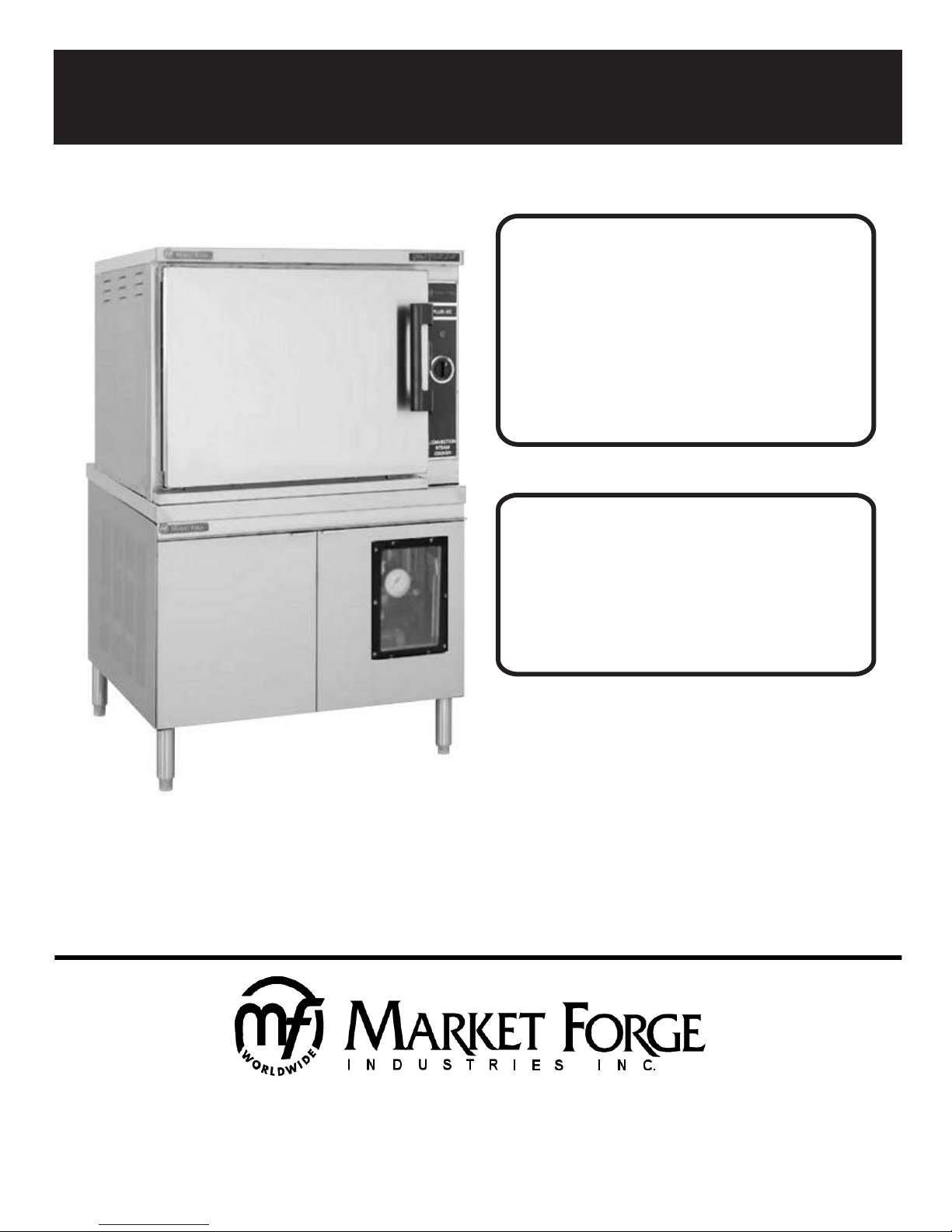
1.1Description ............................................
1.2Basic Functioning .................................
1.3Service ..................................................
SECTION 2 INSTALLATION
2.1Assembly ..............................................
2.2Setting in Place .....................................
2.3Mechanical Connections ......................
2.4W ater Connections ...............................
2.5Installation Check-Out ..........................
2.5.1Initial Control Settings ...........................
2.5.2Cooker Check-Out ................................
2.5.3Shut-Down Procedure ..........................
2.6Reversing the Doors .............................
SECTION 3 OPERATION
3.1Operating Controls & Indicators ...........
3.2Operating Procedures ..........................
3.2.1Steam Source Operation ......................
3.2.2Preheating ............................................
3.2.3Cooking ................................................
3.2.4Shut-Down Procedure ..........................
3.3Cleaning ...............................................
3.4Drainage ...............................................
3.4.1Cooking Compartment Drainage ..........
3.4.2Drip/Spill Trough Drainage ...................
3.5T est Kitchen Bulletin .............................
SECTION 4 PRINCIPLES OF OPERATION
4.1General .................................................
4.2Plumbing Circuits ..................................
4.2.1Steam Inlet Line ....................................
4.2.2Steam Exhaust & Drain Lines ...............
4.2.3Steam Exhaust Condensing System ....
4.3Electrica Circuits ...................................
4.3.1Control Circuit Components .................
4.3.1.160 MinuteTimer ....................................
4.3.1.2Indicator Lights .....................................
4.3.1.3Buzzer ..................................................
4.3.1.4Door Interlock Switch ............................
4.3.1.5Thermostatic Switch .............................
SECTION 5 TROUBLE-SHOOTING
5.1General .................................................
5.2T rouble-Shooting ..................................
5.3Electrical Fault Isolation ........................
5.4Elec Trouble-Shooting Procedures .......
5.4.1Incoming Power ....................................
5.4.2Electrical Inspection ..............................
5.4.360 Minute Timer ....................................
5.4.3.1Timer Contacts .....................................
5.4.3.2Timer Motor ..........................................
5.4.4Door Interlock Switch ............................
5.4.5Steam Solenoid V alves .........................
5.4.6Indicator Lights .....................................
5.4.7Cooking Compartment Thermostat
Switch ...................................................
PARAGRAPH
5.4.8Buzzer ..................................................
5.4.9Cold W ater Condener Circuit ................
5.4.10Wiring ...................................................
SECTION 6 MAINTENANCE
6.1General .................................................
6.2Preventive Maintenance .......................
6.2.1Cooking Compartment Cleaning ..........
6.3Repair & Replacement .........................
6.3.1Door Latch Tension Adjustment ............
6.3.2Door Handle Tension Adjustment .........
6.3.3Door Gasket Replacement ...................
6.3.4Exterior Panel Removal ........................
6.3.5Steam & W ater Solenoid Valve
Replacement ........................................
SECTION 7 ILLUSTRATED PARTS LIST
7.1General .................................................
7.2Ordering Information .............................
7.3Index of Illustrated Parts List ................
7.4Illustrated Parts List ..............................
LIST OF TABLES
TABLE
SECTION 3 OPERATION
3-1Controls & Indicators ............................
SECTION 5 TROUBLE-SHOOTING
5-1General Trouble-Shooting Guide ..........
5-2Electrically Fault Isolation Guide ..........
LIST OF ILLUSTRATIONS
FIGURE
SECTION 2 INSTALLATION
2-1T ypical Door Layout ..............................
SECTION 3 OPERATION
3-1Controls & Indicators ............................
SECTION 4 PRINCIPLES OF OPERATION
4-1Pictorial Diagram -
Steam & W ater Circuits ........................
SECTION 5 TROUBLE-SHOOTING
5-1Wiring Diagram, ST -12 .........................
5-2Schematic Diagram, ST -12 ...................
SECTION 7 ILLUSTRATED PARTS LIST
7-1Cabinet Assembly .................................
7-2Door Assembly .....................................
7-3Control Panel Assembly .......................
7-4Condenser Assembly ............................
PAGE
1-1
1-1
1-1
2-1
2-1
2-1
2-1
2-1
2-2
2-2
2-2
2-2
3-1
3-1
3-1
3-1
3-1
3-1
3-2
3-2
3-2
3-2
3-2
4-1
4-1
4-1
4-1
4-1
4-2
4-3
4-3
4-3
4-3
4-3
4-3
5-1
5-1
5-1
5-1
5-2
5-2
5-3
5-3
5-3
5-6
5-6
5-6
5-6
PAGE
5-6
5-7
5-7
6-1
6-1
6-1
6-1
6-1
6-2
6-2
6-2
6-2
7-1
7-1
7-1
7-2/7-6
3-3
5-1
5-2
2-3
3-2
4-2
5-4
5-7
7-3
7-4
7-5
7-6