3INSTALLATION
Installation Information
UNPACKING
Immediately after unpacking, check for possible shipping
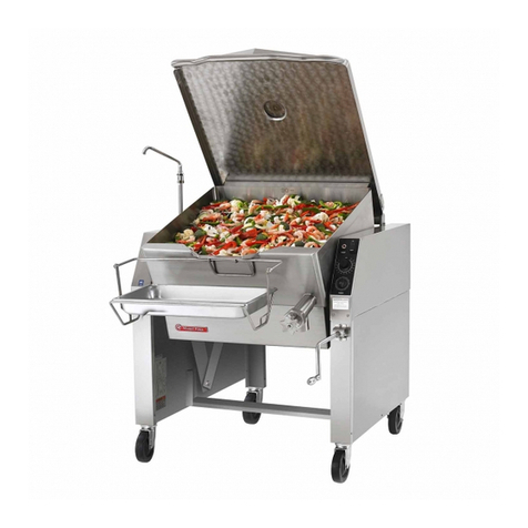
damage. If the tilting universe plus electric skillet is found
to be damaged, save the packing material and contact the
carrier within 15 days of delivery.
Before installing, verify that the electrical service agrees
with the specications on the rating plate located on the
right side panel as you face the front of the skillet. If the
supply and equipment requirements do not agree, contact
your dealer.
SHIPPING DAMAGE CLAIM PROCEDURE:
The equipment is inspected & crafted carefully by skilled
personnel before leaving factory. The transportation com-
pany assumes full responsibility for safe delivery upon ac-
ceptance of this equipment.
If shipment arrives damaged:
1. Visible loss or damage: Note on freight bill or express
delivery and have signed by the person making de-
livery.
2. File claim or damages immediately Regardless of the
extent of damages.
3. Concealed loss or damage: If damage is noticed after
unpacking, notify the transportation company imme-
diately and le ‘concealed damage’ claim with them.
This should be done within fteen days from the date
delivery is made to you. Retain container for inspec-
tion.
LOCATION
The installation location must allow adequate clearances
for servicing and proper operation. A minimum front clear-
ance of 36”, and rear clearance of 6” is required.
INSTALLATION CODES AND STANDARDS:
Your Tilting Universe Plus Electric Skillet must be installed
in accordance with:
4. Provincial and local codes, with: USA state and local
codes, or in the absence of local codes, with: The
National Electrical Code ANSI/NFPA-70 (Latest Edi-
tion), or in the absence- of local codes, with: Canada
CSA C22.1 Canadian Electrical Code, Part 1.
5. ANSI/NFPA Standard #96, “Vapor Removal from
Cooking Equipment”, (Latest Edition), available from
Tha National Fire Protection Association, Battery-
march Park, Quincy, Massachusetts (MA) 02269.
LEVELING AND ANCHORING THE SKILLET:
1. Place the skillet in the desired location of installation.
2. Place a carpenter’s level on the top of the skillet pan
and turn the adjustable feet to level the skillet from
side-to-side and front-to-back.
3. Mark hole locations on the oor through the anchor-
ing holes provided in the rear adjustable ange feet.
4. Remove the skillet from the anchoring holes marks
that you marked on the oor and drill a hole for each
marking. After all holes have been drilled, place the
skillet back into original position.
5. Check to make sure the skillet is still level. (See Step
2).
6. Bolt and anchor the skillet securely to the oor, then
seal the bolt and anged feet with a silastic or equiva-
lent compound.
7. If faucet is provided, connect water supply and check-
operation.
8. Turn the power on and check for proper operation.
ELECTRICAL CONNECTION
WARNING
Electrical and grounding connections must
comply with the appliance portions of The
National Electrical Code and/or other local
codes.
NOTE Do not install in such a manner that a service per-
son cannot remove the control box cover.
1. Connect unit to a branch circuit having a voltage and
circuit type specied on the name plate and of suf-
cient size to carry load. The amps per line wire for the
various voltage rating are shown in the table.
NOTE: Supply wires must be suitable for tempera-
ture of at least 200°F (90°C). Additionally,
all wiring must conform to the requirements
of local and national electric codes. Conduit
and ttings must be watertight.
2. Connect ground wire from electrical service to ground
lug.
3. Ensure that skillet is rmly seated on frame before
checking connection and functioning of controls.
NOTE: Unit is equipped with an interlock switch that
shuts off current to the heating elements
when skillet pan is more than (10°) above
normal horizontal cooking position.
4. Switch on current supply to unit. Check for proper fuc-
tioning of controls and heating elements.
