Market Forge Industries STM-EX User manual

Your Sterilizer Experts
Manufacturing –Distribution –Maintenance- Guaranteed!
Alfa Medical 1-800-762-1586
265 Post Ave 516-280-7822
Westbury, NY 11590 516-280-7832 fax
www.sterilizers.com
The attached manual is for your records.
Go to the below web site to look for parts
http://bit.ly/Market-Forge-Sterilmatic-Parts

35 Garvey Street
Everett, Massachusetts 02149

1
TABLE OF CONTENTS
SECTION 1 INSTALLATION INSTRUCTIONS
INSTALLATION ........................................................................................................................................................................... 2
ELECTRICAL .............................................................................................................................................................................. 2
OUTSIDE VENTING .................................................................................................................................................................... 2
WATER-COOLED EXHAUST CONDENSER .............................................................................................................................. 2
RECORDING THERMOMETER .................................................................................................................................................. 2
TRAY SUPPORTS ...................................................................................................................................................................... 3
BAFFLE INSTALLATION ............................................................................................................................................................ 3
OPERATION CHECK .................................................................................................................................................................. 3
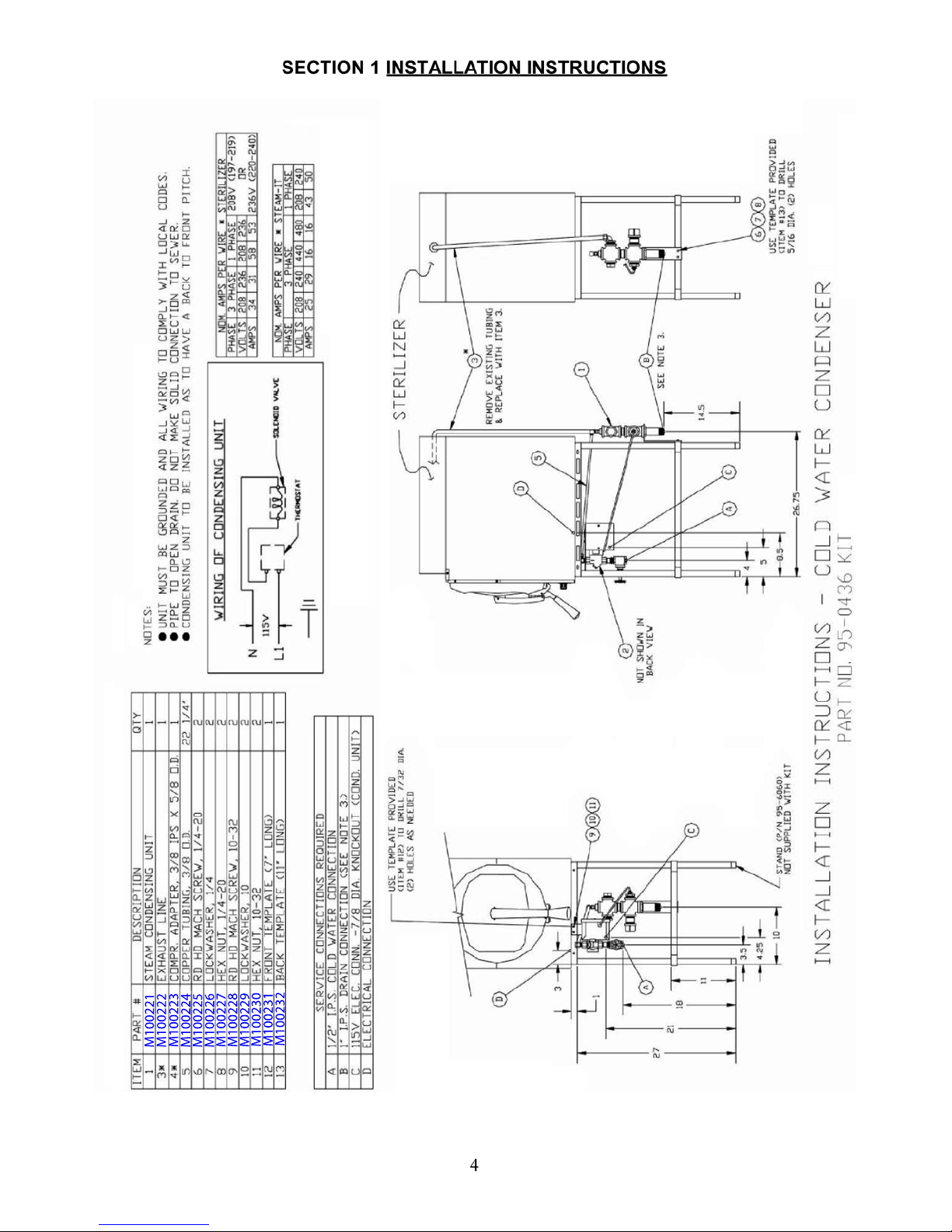
INSTALLATION INSTRUCTIONS FOR COLD WATER CONDENSER ....................................................................................... 4
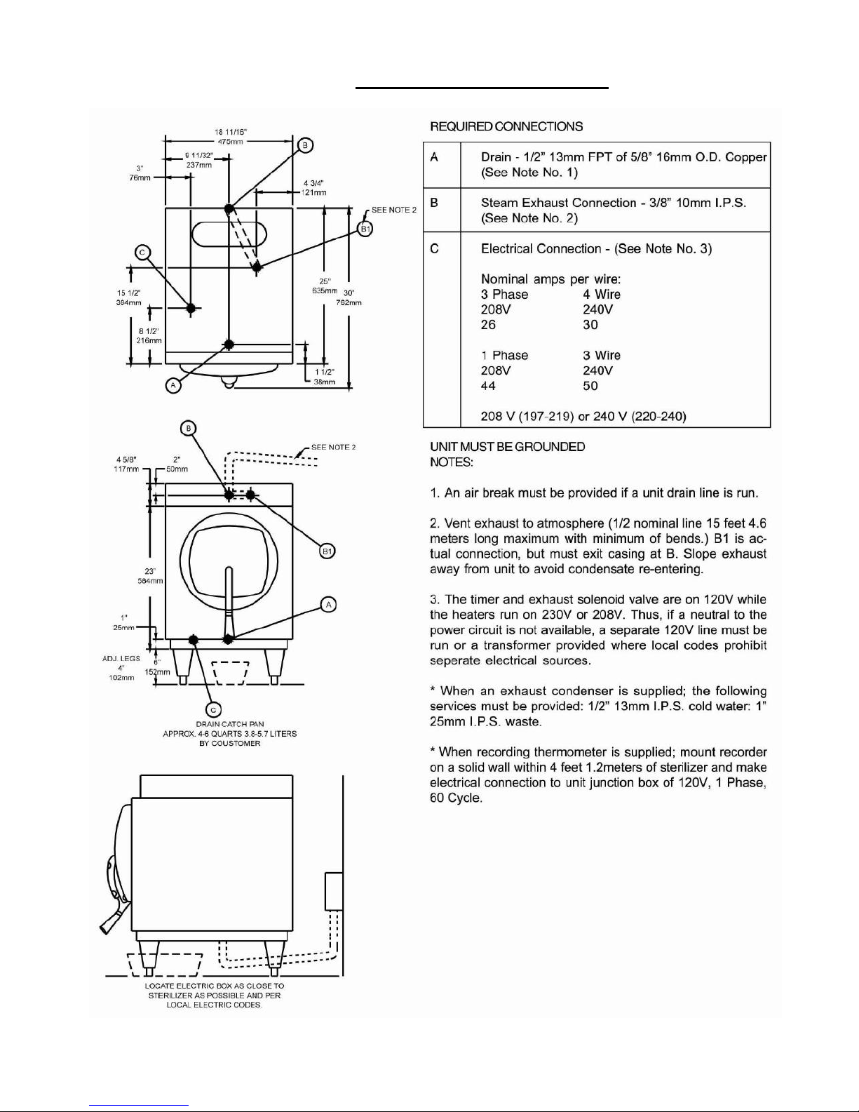
REQUIRED CONNECTIONS ...................................................................................................................................................... 5
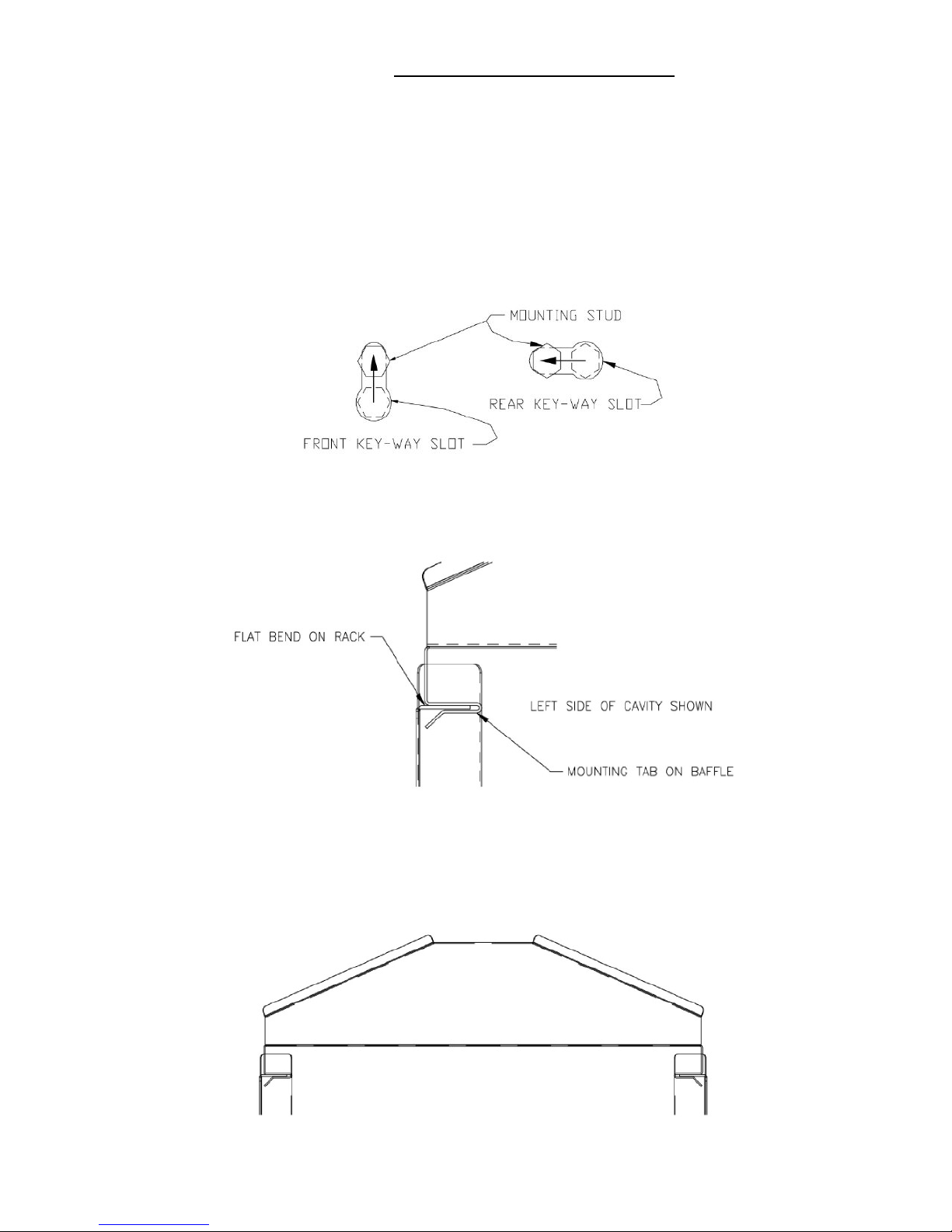
INSTALLING PAN SUPPORTS AND BAFFLES ......................................................................................................................... 6
ELECTRICAL SUPPLY CONNECTIONS FOR STM-E AND STM-EL........................................................................................... 7
ELECTRICAL SUPPLY CONNECTIONS FOR STM-EX AND STM-ELX ..................................................................................... 7
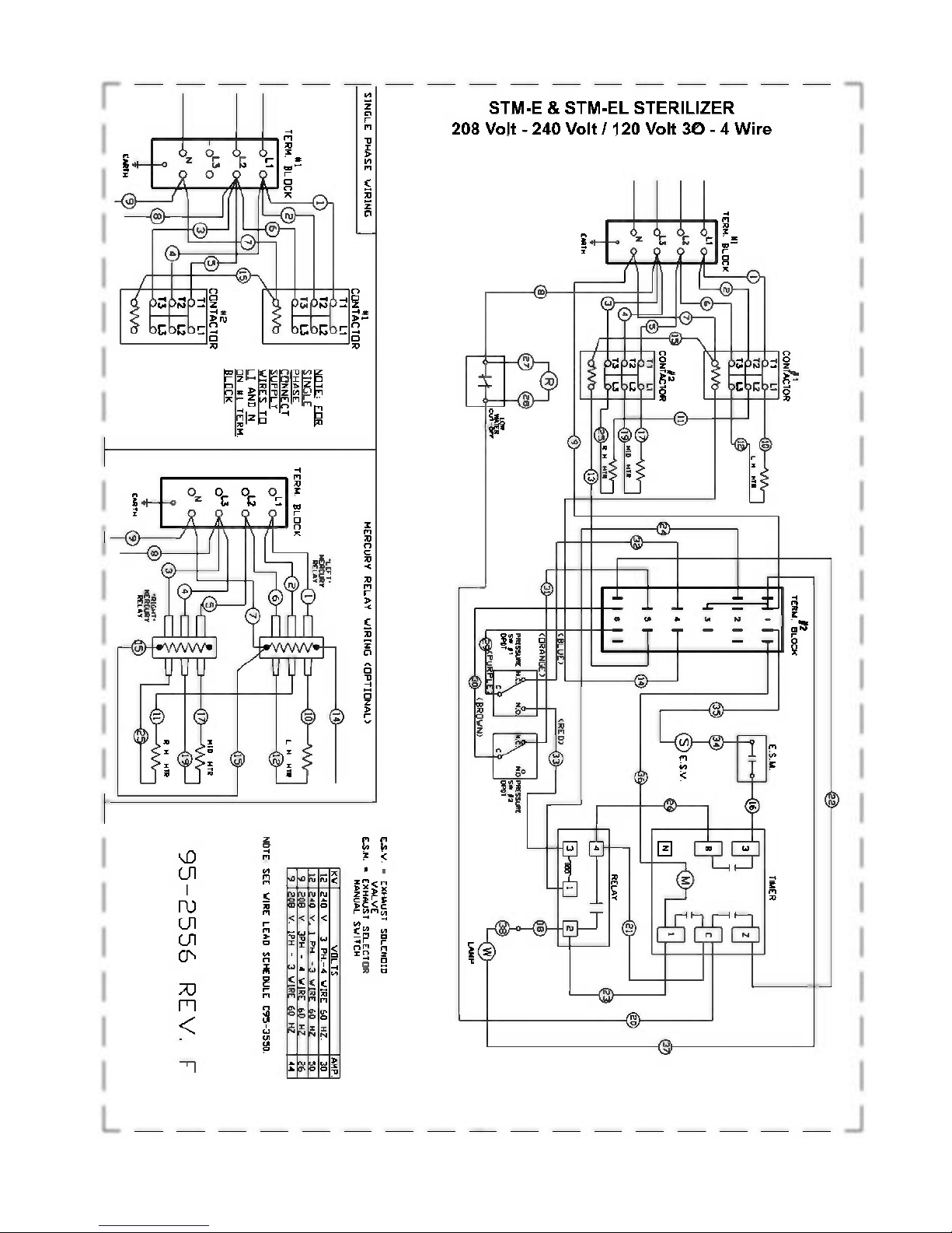
DOMESTIC WIRE DIAGRAM FOR STM-E AND STM-EL ........................................................................................................... 8
DOMESTIC WIRE DIAGRAM FOR STM-EX AND STM-ELX ...................................................................................................... 9
TYPICAL CIRCUIT CONNECTION FOR STM-E AND STM-EL ...................................................................................................10
TYPICAL CIRCUIT CONNECTION FOR STM-EX AND STM-ELX EXPORT ...............................................................................11
INSTALLATION FOR OPTIONAL RECORDING THERMOMETER .............................................................................................12
TO REMOVE THE CHART ..........................................................................................................................................................12
TO INSTALL NEW CHART .........................................................................................................................................................12
PEN ADJUSTMENT ....................................................................................................................................................................12
REPLACEMENT PARTS FOR 24 HOUR THERMOMETER ........................................................................................................12
SECTION 2 WATER CONDITIONS ............................................................................................................................................13
SECTION 3 OPERATING INSTRUCTIONS
OPERATING INSTRUCTIONS ....................................................................................................................................................14
STERILIZATION GUIDE .............................................................................................................................................................15
MINIMUM STERILIZATION TIMES .............................................................................................................................................16
SECTION 4 DAILY CLEANING
DAILY CLEANING PROCEDURE ...............................................................................................................................................16
SECTION 5 ASSEMBLY
STERILMATIC OPEN STAND .....................................................................................................................................................17
STERILMATIC OPEN STAND WITH CONDENSER ...................................................................................................................17
PARTS LIST FOR CONDENSER WITH OPTIONAL STAND ......................................................................................................17
STERILMATIC DOOR ASSEMBLY .............................................................................................................................................17
DOOR ADJUSTMENT .................................................................................................................................................................18
THE DOOR GASKET ..................................................................................................................................................................18
DOOR LIFT SPRING ...................................................................................................................................................................18
TO REMOVE THE DOOR ASSEMBLY .......................................................................................................................................19
DOOR ASSEMBLY PARTS LIST ................................................................................................................................................19
THE FULCRUM AND DRAIN ASSEMBLY ..................................................................................................................................20
FULCRUM AND DRAIN PARTS LIST .........................................................................................................................................20
ROLLER ASSEMBLY ..................................................................................................................................................................21
DOMESTIC – THE PRESSURE ACTUATED TEMPERATURE CONTROL, STM-E AND STM-EL .............................................21
DOMESTIC – HOW IT WORKS .................................................................................................................................................. 21
DOMESTIC – ADJUSTING THE RANGE OR OPERATION, STM-E ...........................................................................................21
EXPORT - THE PRESSURE ACTUATED TEMPERATURE CONTROL, STM-EX AND STM-ELX .............................................22
EXPORT – HOW IT WORKS ...................................................................................................................................................... 22
EXPORT – CHECKING THE 100o
C SETTING, STM-ELX ...........................................................................................................22
EXPORT – ADJUSTING THE RANGE OF OPERATION, STM-ELX ...........................................................................................22
DOMESTIC – CHECKING THE 230oSETTING, STM-EL ........................................................................................................... 23
DOMESTIC – ADJUSTING THE RANGE OF OPERATION, STM-EL .........................................................................................23
CAST-IN THE HEATING ELEMENTS .........................................................................................................................................23
THE LOW WATER CUT-OFF (MANUAL RESET) .......................................................................................................................23
THE ELECTRIC CONTACTORS .................................................................................................................................................23
THE TIMER .................................................................................................................................................................................24
THE STEAM PRESSURE GAUGE ..............................................................................................................................................24
THE SAFETY VALVE ..................................................................................................................................................................24
THE FLUE ...................................................................................................................................................................................24
THE EXHAUST SOLENOID VALVE ............................................................................................................................................24
TO REPLACE A THERMOSTATIC ELEMENT ............................................................................................................................25
THE STEAM TRAP .....................................................................................................................................................................25
HOW IT WORKS .........................................................................................................................................................................25
SECTION 6 ILLUSTRATED PARTS
MASTER ILLUSTRATION AND PARTS, STM-E AND STM-EX .......................................................................................... 26 & 27
MASTER ILLUSTRATION AND PARTS, STM-El AND STM-ElX ......................................................................................... 28 & 29
CONTROL CONSOLE PARTS LIST FOR STM-E AND STM-EX .................................................................................................30
CONTROL CONSOLE PARTS LIST FOR STM-EL AND STM_ELX.............................................................................................31
DOOR HANDLE PARTS LIST .....................................................................................................................................................32
SECTION 7 TROUBLE SHOOTING
STEAM TRAP TROUBLE-SHOOTING ........................................................................................................................................33
TROUBLE-SHOOTING GUIDE ...................................................................................................................................................33
SECTION 8 WARRANTY INFORMATION ..................................................................................................................................34

2
SECTION 1 INSTALLATION INSTRUCTIONS
AUTOMATIC STERILMATIC STEAM PRESSURE STERILIZER
MODELS: STM-E, STM-EL, STM-EX & STM-ELX
Your Sterilmatic Sterilizer has been developed to answer the need for a compact, automatic,
low-cost steam pressure sterilizer. The following instructions cover installation. Should
service be required, it is readily available by contacting our authorized service agency
located nearest to you. The name of your local service company can be obtained from your
Market Forge Representative in your area or by contacting the Service Department at Market
Forge Co., 35 Garvey Street, Everett, MA 02149, Tel. (617) 387-4100.
INSTALLATION
Set sterilizer on counter, using the 4" (102mm) legs provided or assemble the an optional
stainless steel stand with under-shelf. If your Sterilmatic includes a water-cooled exhaust
condenser, we recommend the use of the Sterilmatic stand, part number 95-6060. First, level
unit in place, then adjust front legs to pitch the unit forward 1/4" (6mm) to insure positive
drainage of the cylinder.
ELECTRICAL
Connect to proper electrical supply box and disconnect switch as shown on one of the
following schematic diagrams-208 or 240 volts, single or three phase. Connection is located
behind the terminal box cover at the lower left side of unit. Whether the supply current is 208
volt or 240 volt, single or three phase, all control circuits are 120 volts. In order to accomplish
this connection, a current-carrying grounded neutral must be provided. Thus, a three phase
system must be 4-wires and a single phase system must be 3-wires. If a current-carrying
grounded neutral is not available from the power source, a separate 120 volt circuit must be
run. Most electrical codes require, and we recommend, that a separate disconnect switch be
located within sight of the sterilizer. When separate 120 volt control circuit must be run, this
must also be part of the disconnect box assembly.
OUTSIDE VENTING
Connect 1/2" (13mm) nominal tubing exhaust to outside vent connection located on the top
of the control housing. IMPORTANT: Exhaust line must be vented to the outside to eliminate
the exhausted steam and the accompanying noise from entering the room. Use 1/2" (13mm)
copper tubing or suitable alternate. Length of the line should not exceed 15 feet (4.5 meters)
and should have a minimum of bends. The line should slope downward after leaving the
sterilizer in order to insure condensate drainage.
WATER-COOLED EXHAUST CONDENSER
If outside venting is not possible, an optional water-cooled condenser is available for
connection to an open drain. If required order part number 95-0436 kit.
RECORDING THERMOMETER
If a recording thermometer is provided, refer to installation guide provided with recorder.

3
SECTION 1 INSTALLATION INSTRUCTIONS
TRAY SUPPORTS
Install side tray supports. Tray supports are attached by means of key-hole clearance slots
which are slipped over studs located on the sides of the Sterilmatic chamber.
BAFFLE INSTALLATION
To insure maximum drying of packs, a baffle is supplied with your STM-E Sterilmatic. Place
perforated splash baffle in bottom of the sterilizing chamber. Install small baffle with no
perforation at the rear of the upper tray support channel.
OPERATION CHECK
To check for proper operation of unit:
1. Close drain valve by turning handle clockwise.
WARNING:
DO NOT OPEN DRAIN VALVE WHILE UNIT IS OPERATING. PREMATURE OPENING
MAY RESULT IN SCALDING OF OPERATOR.
2. Fill chamber with 4 to 6 quarts (3.7 to 5.6 liters) of ordinary tap water. DO NOT USE
DISTILLED OR DIONIZED WATER.
3. Close chamber door.
4. Set exhaust selector to INSTRUMENTS AND PACKS (fast exhaust) or LIQUIDS (slow
exhaust).
5. Set timer to 15 minutes. Cycle will go to completion automatically.
NOTE: Cycle timer will not start until sterilizing temperature is obtained.


5
SECTION 1 INSTALLATION INSTRUCTIONS

6
SECTION 1 INSTALLATION INSTRUCTIONS
INSTRUCTIONS FOR INSTALLING PAN SUPPORTS AND BAFFLES
1. Locate the mounting studs on the inside of the chamber. There are two rack mounting studs on each side.
2. Taking one pan support and positioning rack so that the pan stop is facing the rear of the unit and the wires
are facing toward the center of the unit. The pan stop is a piece of sheet metal welded to the rack with a 65o
bend.
3. Begin to hang the pan support by placing the rear key-way slot onto the rear mounting stud and slide the
rack until the slot sits on the mounting stud. When this is done correctly the front mounting stud will be in
position to place the front key-way slot. Slide the rack down into its correct position. See Fig. 1.
Fig. 1.
4. After installing one pan support rack correctly, you can install the baffle. Position the baffle so that the 45o
bend is facing up and towards the front of the unit. Slide the mounting tab onto the flat bend on the pan stop
bracket. The baffle should now stay in place by itself, but in a tilted state. See Fig. 2.
Fig. 2.
5. Position the second pan support rack into the cavity and slide the other mounting tab onto the rack flat bend
while the pan support rack is not on the mounting studs. Hang the pan support by placing the rear key-way
slot onto the rear mounting stud and slide the rack until the slot sits on the mounting stud. When this is done
correctly the front mounting stud will be in position to place the front key-way slot. Slide the rack down
into its correct position. See Fig. 3.
Fig. 3.

7
SECTION 1 INSTALLATION INSTRUCTIONS
THE ELECTRIC SUPPLY CONNECTIONS FOR STM-E AND STM-EL
Connect to proper electrical supply as indicated on nameplate on top of unit. Connection is
located behind the terminal box cover at the lower left side of unit. Whether the supply
current is 208 or 240 volt, single phase or three phase, all control circuits are 120 volts. In
order to accomplish this, a current-carrying grounded neutral must be provided.
Thus, a three phase system must be 4-wires and a single phase system must be 3-wires. If a current-
carrying grounded neutral is not available from the power source, a separate 120 volt circuit must be
run. Most electrical codes require, and we recommend, that a separate disconnect switch be located
within sight of the sterilizer. When a separate 120 volt control circuit must be run, this must also be
part of the disconnect box assembly.
THE ELECTRIC SUPPLY CONNECTIONS FOR STM-EX AND STM-ELX EXPORT
Connect to proper electrical supply as indicated on nameplate on top of unit. Connection is located
behind the terminal box cover at the lower left side of the unit. All control circuits are 220 volts.
In order to accomplish this, a current-carrying grounded neutral must be provided.
Thus, a three phase system must be 4-wires. Most electrical codes require, and we recommend, that
a separate switch be located within sight of the sterilizer.

8
SECTION 1 INSTALLATION INSTRUCTIONS

9
SECTION 1 INSTALLATION INSTRUCTIONS

10
SECTION 1 INSTALLATION INSTRUCTIONS
TYPICAL CIRCUIT CONNECTION FOR STM-E AND STM-EL

11
SECTION 1 INSTALLATION INSTRUCTIONS
TYPICAL CIRCUIT CONNECTION FOR STM-EX AND STM-ELX EXPORT MODELS

12
SECTION 1 INSTALLATION INSTRUCTIONS
INSTALLATION FOR OPTIONAL RECORDING THERMOMETER
The Optional Recording Thermometer may be surface or panel mounted as best accommodates the layout of
the sterilization area.
1. Remove the top cover. Remove the pipe plug located in the Y-fitting that also accommodates the
safety relief valve and which is connected directly to the sterilizing chamber.
2. Insert the thermometer bulb of the temperature recorder into the pipe, from which the plug was
removed.
3. Tighten the fittings. Bend that portion of the Thermometer bulb coil that extends inside the shell
toward the rear of the cylinder and at an angle of 45° so that it does not interfere with mounting
the overhead baffle plate (Item #20 Master Illustration).
4. For mounting the recorder on a wall or on the unit itself, the 3/16" diameter tapped holes in the
angles which are attached to the recorder must be drilled out. This allows for the use of wood or
sheet metal screws on walls or panels, and nuts and bolts on the unit itself.*
5A. Electrical connections to the recorder are made by running a line from the recorder to any 120
volt supply. Connection can also be made at the supply connection for the unit by utilizing the
proper wires to gain 120 volts. Connect either L 1, L2, or L3 for power lead (black wire and the
neutral white wire) line for the other side of the 120 volt line.
5B. Electrical connections to the recorder are made by running a line from the recorder to any 220
volt supply. Connection can also be made at the supply connection for the unit by utilizing the
proper wires to gain 220 volts. Connect either L 1, l2, L3 for power lead (black wire and the
neutral white wire) line for the other side of the 220 volt line.
6. The United Electric Recording Thermometer is a 24 hour clock and should be run continuously.
Charts should be changed every 24 hours.
"For further mounting instructions. see the Manufacturers Instruction and Maintenance Instructions, Form #17-0099."
TO REMOVE THE CHART
1. Unscrew and remove the chart knob and lift the pen by depressing the pen lifter.
2. Grasp edge of the chart, lift off the chart hub and slide downward and out without permitting the
paper to touch the pen.
TO INSTALL NEW CHART
1. Slide edge of the chart under the pen and over the hub, insert the upper edge under the
nameplate chart guide and seat the chart hole on the hub.
2. Set correct chart time to the chart plate time index line and replace the knob.
PEN ADJUSTMENT - If the pen point is not aligned properly with the temperature to be recorded (as
checked by an ordinary thermometer), it may be corrected in the following manner:
1. Locate the small fillister head screw on the right side of the extreme upper end of the Pen
Assembly.
2. Turn the screw clockwise for pen movement toward the hub (or counter-clockwise for pen
movement away from the hub) until the temperature value of the ink line has been adjusted to its
proper position.
PART NO. 10-7933 REPLACEMENT 24 HOUR THERMOMETER CHART FAHRENHEIT
PART NO. 08-6244 REPLACEMENT 24 HOUR THERMOMETER CHART CELSIUS

13
SECTION 2 WATER CONDITIONS
Market Forge from time to time is asked the question about using distilled or dionized water
for use with our Sterilizer models STM-E and STM-EL. We are always asked why these
water choices are not allowed for use with our units and what would be recommended. To
address this situation, we have complied the following as a means of satisfying these
questions:
1. We have found that the use of distilled or dionized water will aggressively attack the
pure coat of Aluminum Alclad, which protects the bottom surface from oxidizing and
then eventually pitting (reference: Operating and Maintenance Instructions).
2. In addition pitting can also be caused by several other external environmental factors.
Few examples are as follows. These conditions have been highlighted in our
documentation.
Grains of hardness in the water supply should be as follows (.25 to 2).
a pH imbalance in the water supply can greatly affect the life to the aluminum
cylinder. The pH range that would be recommended is between 7.0-8.5.
The lack of a positive electrical ground can cause an electrolytic reaction that
will accelerate pitting.
Another contribution to accelerate pitting is the type of cleaning solutions used
or the abrasive scrubbing pads. If a low pH is present with the detergents being
used or an abrasive pad, the protective Alclad coating will be removed during
the cleaning process.
Spillage of media being sterilized can also contribute to the accelerated pitting if
it is corrosive.
IMPORTANT NOTE:
Market Forge will not be responsible for damage resulting from the use of hard or
corrosive water, from failure to drain the unit daily, or from inadequate cleaning
procedures.

14
SECTION 3 OPERATING INSTRUCTIONS
OPERATING INSTRUCTIONS:
1. IMPORTANT: Make sure the drain valve is closed. Fill bottom of the sterilizer
chamber with approximately six quarts of water of just bellow ledge at bottom of door
opening. (If water supply is known to be hard or corrosive, a source of treated water
should be used.) DO NOT USE DISTILLED WATER. (See page 13)
2. LOAD STERILIZER: Use proper sterilizer loading procedures when placing materials
in sterilizer chamber. All solid containers or instruments must be placed so that water
or air will not be trapped in them.
3. CLOSE DOOR: Grasp handle, and holding it in vertical position, pull door down until
bottom of door rests in the bottom of door opening. Then rotate handle forward,
engaging the lower curved portion under the horizontal rod in the casting at the bottom
of the door opening. Push handle all the way down and back until door is locked
securely in position.
4. SET EXHAUST SELECTOR: Located at center of the control housing mounted on
top of the unit, to correct position. Unit is now ready to start. All items, other than
solutions, may be sterilized with selector at "Instruments". Solutions require a low
exhaust. Place selector at "Liquids".
5. DETERMINE CORRECT STERILIZATION TIMES: (Referring to pages 15 & 16 for
minimum required times in the sterilization guide and times table.) NOTE: In no case
should the timer be set to less than 15 minutes. Sterilization will not be accomplished
in less than 15 minutes exposure time.
6. TURN TIMER: Located at upper right front of sterilizer. Select desired length of
sterilizing period. This turns power supply on and starts the cycle after pressure-
temperature combination has been reached. Amber pilot light indicates that the timer
is running.
7. When the sterilizer chamber reaches the selected temperature, the timed exposure
cycle will begin. When the exposure cycle is completed, the electric supply will be
opened automatically. When the chamber pressure gauge located at the top of the
control housing reads "0", the door may be opened. (Release handle and let go to
avoid possible contact with remaining steam.) When opening the door, allow a few
seconds for steam to escape from chamber before opening completely.
8. To assist in drying racks, release door handle after pressure has been attained at start
of cycle. Pressure in chamber will keep door closed. The use of a wire basket will
provide better drying for dressings. At end of sterilizing cycle, release door handle and
open slightly. Do not lift door to open position. This will allow steam and moisture to
escape. Allow door to remain in this position for 15 to 20 minutes before removing
load. Small packs can be dried successfully with this procedure. We do not
recommend the sterilization of large packs, such as linens. Be sure condensate
baffles are in position in the chamber.
9. Remove load and check water level for next operation.

15
SECTION 3 OPERATING INSTRUCTIONS
STERILIZATION GUIDE
PACKS (Linens, gloves, etc.) – Use wire basket to facilitate drying. Be sure condensate
baffles are in place. Place packs on edge and arrange load in chamber, so that only minimal
resistant to passage of steam through the load will exist. NOTE: Place gloves in upper two-
thirds of chamber.
JARS, CANISTERS (etc.) – Place containers on side to allow for displacement of air and
complete contact of steam to surfaces. Drying is also facilitated.
PETRI DISHES, PIPETTES, DESICCATORS (etc.) – Should be inverted.
UTENSILS, TREATMENT TRAYS – Placed on edges to facilitate drying.
INSTRUMENT SETS – Place instruments set in trays having mesh or perforated bottoms.
Place trays flat on shelves.
COMBINING FABRICS & HARD GOODS – Place hard goods on lowest shelves.
PLASTIC UTENSILS – DO NOT stack or nest plastic items.
LIQUIDS – Sterilize medium liquids separately from other supplies or materials. Set exhaust
selector to proper position (liquids).
SMALL ITEMS – Sterilize small items in baskets, or trays.

16
SECTION 3 OPERATING INSTRUCTIONS
MINIMUM STERILIZATION TIMES
TIME (Minutes) ARTICLES
15 - Glassware, empty, inverted.
- Instruments, metal in covered or open tray, padded or unpadded.
- Needles, unwrapped.
- Pipettes, blood diluting, serological, volumetric, etc
- Tubing glass (6mm), (10mm) inverted
20 - Flasked solutions 75-250 mo.
- Instruments, metal combined with other materials in
covered and/or padded tray.
- Instruments wrapped in double thickness muslin.
- Rubber gloves, catheters, drains, tubing, etc. Unwrapped
or wrapped in muslin or paper.
30 - Brushes in dispensers, in cans of individually wrapped.
- Dressings, wrapped in paper or muslin, small packs only.
- Flasked solutions 500-1000 ml.
- Needles, luer, individually packaged in glass tubes or paper.
- Syringes, unassembled, individually packaged in muslin or paper.
45 - Flasked solutions 1500-2000 ml.
SECTION 4 DAILY CLEANING
DAILY CLEANING PROCEDURE: (AT THE END OF THE DAY)
a. Remove bottom splash baffle
NOTE: IMPORTANT!
STERILIZING CHAMBER MUST BE CLEANED AND DRAINED DAILY USING THE
FOLLOWING PROCEDURE. WASH WETTED PORTION OF THE CYLINDER
THOROUGHLY BY ADDING A MILD DETERGENT TO WATER IN CYLINDER.
b. If a soft cloth or brush is used with the detergent and does not completely remove the
surface film, a nylon soap pad should be used. After washing thoroughly rinse with clean
water. Dry cylinder* and leave door open overnight.
* The Sterilmatic cylinder is constructed of corrosion resistant Alclad aluminum alloy. The
protective properties of this material afforded to the interior portion of the cylinder which is
exposed to water may be destroyed by allowing a film to form. Such a film can be caused
by salts or other contaminants in the water. Corrosion may also occur if water is not drained
daily.
SECTION 5 ASSEMBLY


18
SECTION 5 ASSEMBLY
DOOR ADJUSTMENT
The Door Adjustment is Located in the
Fulcrum Casting at the base of the door
opening. This adjustment employs the use
of a screw and locknut In order to adjust
the Sterilmatic Door to a tighter closed
position (to prevent steam from leaking by
the door gasket as pressure builds up), it
is necessary to loosen the locknut and
back off the screw at least one-quarter of
a turn and re- tighten the locknut.
THE DOOR GASKET
Keep the gasket clean. With normal
closing and locking of the door assembly,
a steam-tight seal should be made
between the door gasket and the door opening. This seal cannot be maintained if particles of
foreign matter are allowed to accumulate upon either of the contacting surfaces.
If there is leakage by the door gasket before a steam build-up within the cooking chamber
causes it to stop, regard the door assembly as improperly adjusted. A re-adjustment must
then be made of the door screw.
To change the door gasket, remove the entire door assembly as a unit. Discard the old
gasket, replace it with a new one (no cement is required), and reinstall the door assembly.
Make an operational check for leakage and adjust the door, if necessary.
DOOR LIFT SPRING
Market Forge supplies door lift springs in sets only. This policy has been found to be in the
best interest of the customer. Through continuous use, some of the original qualities of the
springs are lost and it becomes advantageous to make replacements to both the left and
right door lift springs in the event that one becomes damaged or broken.
Replacement door lift springs are marked with tabs at the factory prior to shipment to identify
a right from a left spring. These springs must be installed with the right door lift spring on the
right of the door and the left door lift spring on the left of the door as viewed from the front of
the sterilizer.
This manual suits for next models
3
Table of contents
Other Market Forge Industries Steriliser manuals