Market Forge Industries STM-ED User manual

ELECTRIC STERILMATIC STERILIZER
OWNER’S MANUAL
ELECTRIC STERILMATIC STERILIZER
DIGITAL VERSION
03/14 REV. A
H-2117
INSTALLATION
OPERATION
MAINTENANCE
TROUBLE-SHOOTING
PARTS & SERVICE
WARRANTY
•
•
•
•
•
•
DOMESTIC MODEL: □STM-ED EXPORT MODEL: □STM-EDX
35 Garvey Street, Everett, MA 02149
Telephone: (617) 387-4100, (866) 698-3188
Fax: (617) 387-4456, (800) 227-2659
custserv@m i.com, www.m i.com
FORM NO.: Sterilizers.com - Your Sterilizer Expert
Distribution – Maintenance - Guaranteed
Alfa Medical - 10 Bond St Great Neck NY 11021

INTRODUCTION
Product Description ..........................................................i
Service Contacts ..............................................................i
SECTION 1 INSTALLATION INSTRUCTIONS
Service & Technical Information Contact..........................1
Operating Environmental Conditions................................1
Intended Use - Sterilization Cycle ....................................1
Installation ........................................................................1
Electrical...........................................................................1
Outside Venting ................................................................1
Water-Cooled Exhaust Condenser...................................1
Tray Supports...................................................................1
Bafe Installation ..............................................................1
Operation Check...............................................................1
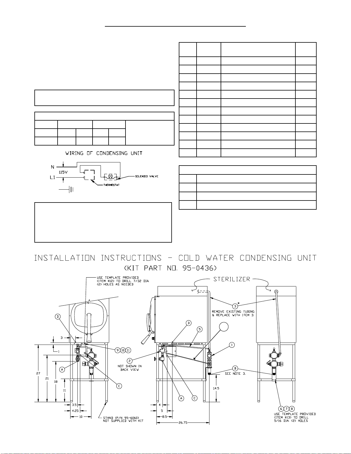
Cold Water Condenser .....................................................2
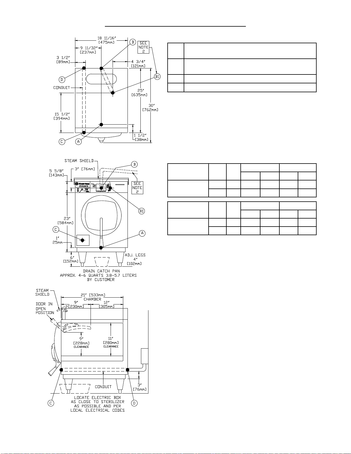
Service Connections.........................................................3
Electrical Requirements....................................................3
Dimensions.......................................................................3
Instructions for Installing Pan Supports & Bafes.............4
Electrical Supply Connections..........................................4
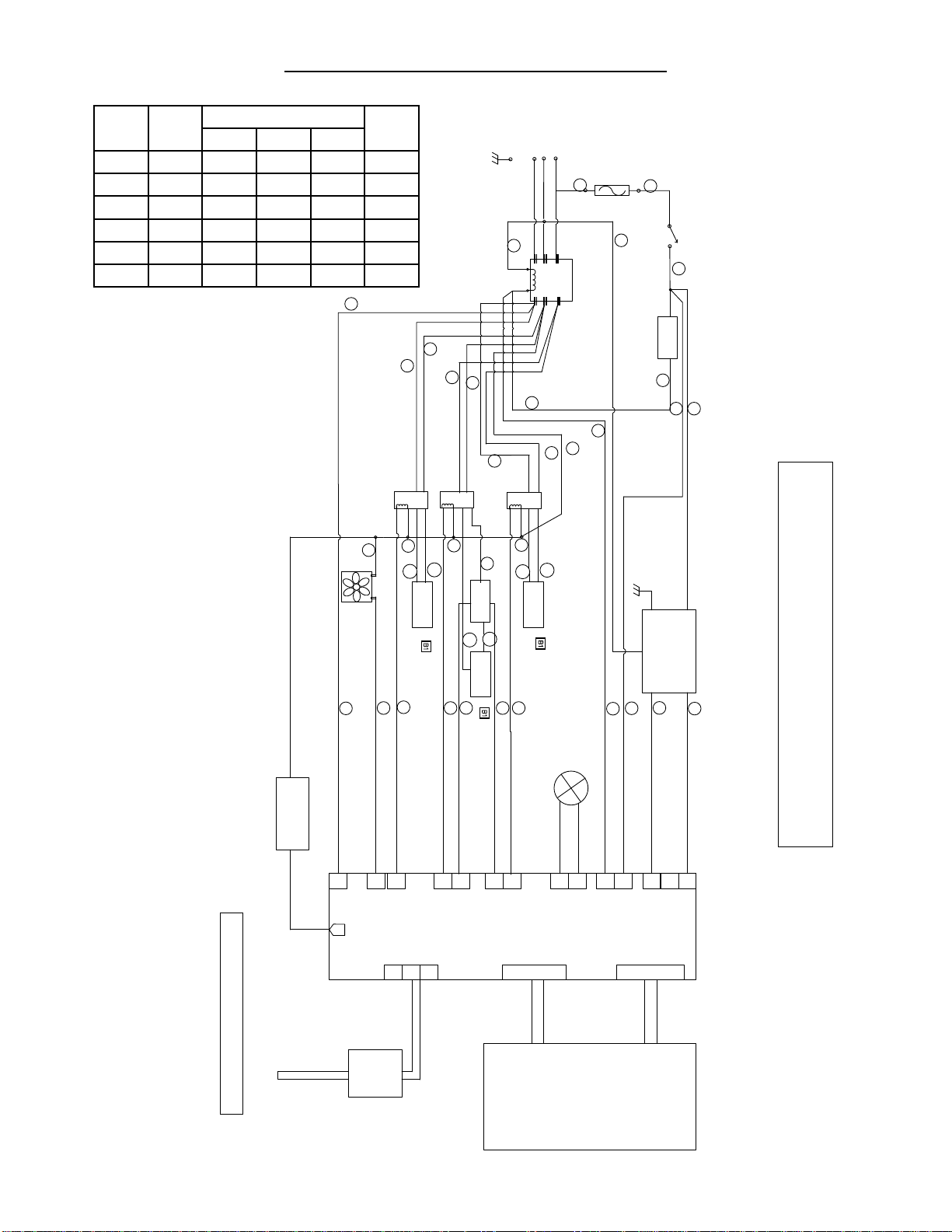
Wiring Diagram - 1 Phase ................................................5
Wiring Diagram - 3 Phase ................................................6
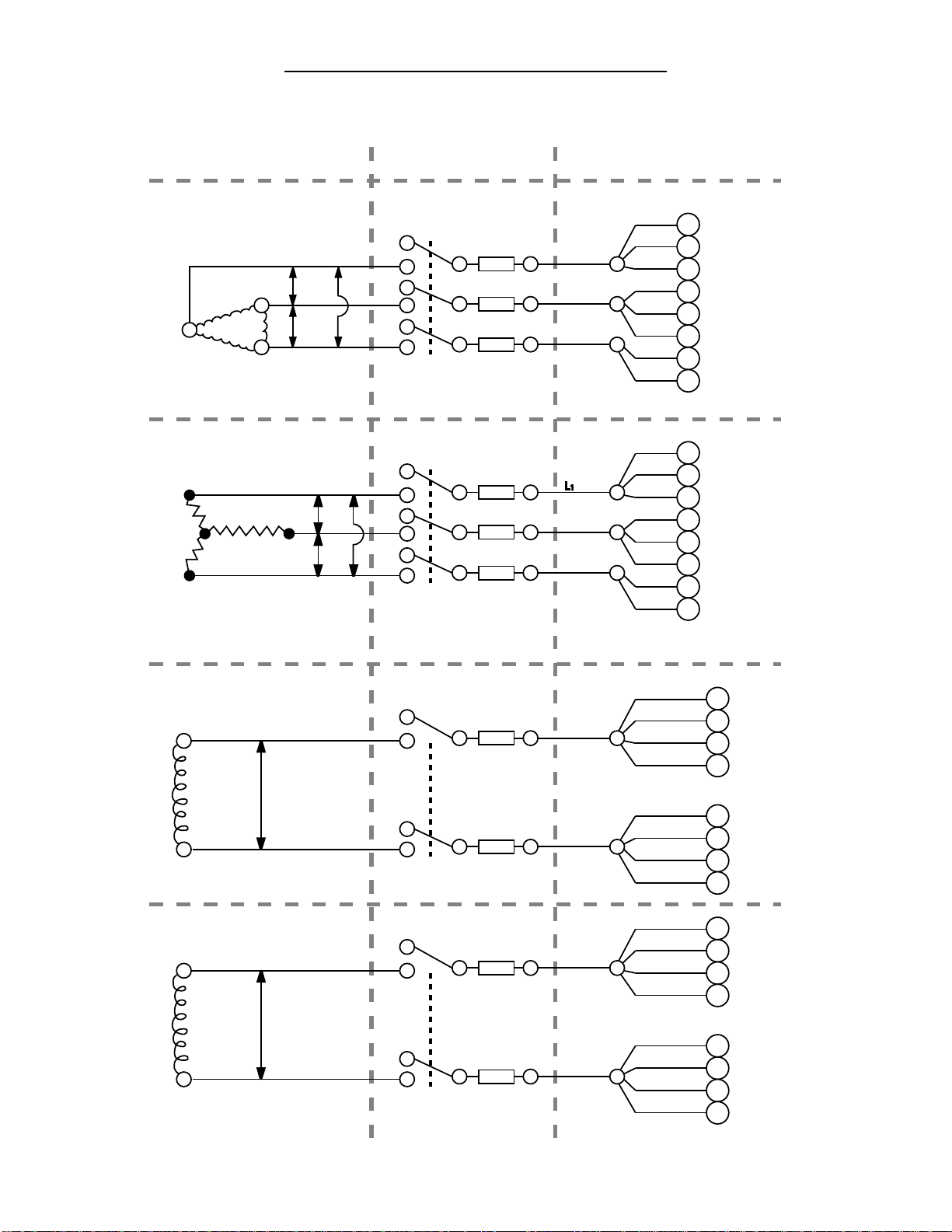
Typical Circuit Connection for STM-ED............................7
SECTION 2 WATER CONDITIONS
Water Conditions ..............................................................9
SECTION 3 OPERATING INSTRUCTIONS
General Operating Instructions.........................................10
Load Sterilizer...................................................................10
Close Door........................................................................10
Determine Correct Sterilization Times..............................10
Sterilization Guide ............................................................10
Minimum Sterilization Times Table ...................................11
CONTROL PANEL
Detailed Operating Instructions ........................................12
Controller Overview..........................................................13
Set Up...............................................................................13
Manual Programing ..........................................................13
Setting Units .....................................................................13
Setting Temperature .........................................................13
Setting Time......................................................................14
Setting Vent Mode ............................................................14
Stopping the Unit..............................................................14
Description of Cycles........................................................14
Preset Keys......................................................................15
Programing Preset Keys...................................................15
Using Preset Keys............................................................15
Printing Data Logger.........................................................15
Print Key...........................................................................16
Printing Previously Run Cycles ........................................16
Printer Paper Cutting........................................................16
Printer paper Changing ....................................................16
Low Water Reset ..............................................................17
Steps to Reset the Unit.....................................................17
Recommended Steps but not Required ...........................17
SECTION 4 MAINTENANCE
Daily Cleaning Procedure.................................................18
SECTION 5 FIELD SERVICE INSTRUCTIONS & ASSEMBLY
Sterilmatic Open Stand.....................................................19
Sterilmatic Open Stand with Condenser...........................19
Parts List for Condenser with Optional Stand...................19
Door Adjustment...............................................................19
Door Assembly .................................................................20
The Door Gasket ..............................................................20
Door Lift Spring.................................................................20
To Remove the Door Assembly ........................................20
The Fulcrum & Drain Assembly........................................21
Roller Assembly................................................................21
Cast-In Heating Elements.................................................22
Low Water Cut-Off Manual Reset.....................................22
Saftey Valve......................................................................22
The Flue ...........................................................................22
Echaust Solenoid Valve....................................................22
SECTION 6 ILLUSTRATED PARTS LIST
Vent Piping .......................................................................23
Electrical Components......................................................24
Sterilizer Assembly ...........................................................25
Pan Supports & Bafe ......................................................26
Door Handle Assembly.....................................................27
SECTION 7 TROUBLE-SHOOTING
Trouble Shooting Guide....................................................29
SECTION 8 APPENDIX
Error Codes ......................................................................30
SECTION 9 WARRANTY INFORMATION
Sterilizer Warranty ............................................................31
Sterilizer Warranty Resistration ........................................32
TABLE OF CONTENTS

A. Product Description:
The Market Forge Sterilmatic Sterilizer with Digital Controller (model STM-ED) is a compact, automatic, low cost
steam pressure sterilizer (autoclave).
The sterilizing cylinder is a 3/16” (4.8mm) thick wall, welded aluminum. The exterior is made of polished stainless
steel. Interior dimensions of 16” (406mm) diameter and 26” (660mm) long with a cubic content of 5,220 cubic
inches (0.085 cubic meters) and has a door opening of 13-1/2” (343mm) wide and 11” (279mm) high. The steril-
izing compartment has a pan capacity of:
□ (3) 12” x 20” x 2 ½” (305mm x 508mm x 64mm) or,
□ (2) 12” x 20” x 4” (305mm x 508mm x 102mm) or,
□ (1) 12” x 20” x 6” (305mm x 508mm x 152mm)
The sterilizer door is a self-sealing type that cannot be opened until the steam pressure is completely exhausted
from the chamber. The door is 12 gauge stainless steel and removable for cleaning without tools. The door gas-
ket is one-piece molded, also replaceable without tools or cement.
The sterilizing cycle is fully automatic with the time, temperature and venting controlled by the microprocessor
based, digital controller.
The sterilizing temperature can be set anywhere in a range from 225°F (107°C) and 250°F (121°C). There is an
on-board data logger/printer. The data logger records the time, temperature and pressure for each sterilization
cycle. This data can be stored for future printing or printed out following each cycle.
B. Service Contacts:
Should repairs be required, a network of authorized agencies is available to assist with prompt service. A current
Directory of Authorized Service Agencies may be obtained by contacting:
Market Forge Industries, Inc.
35 Garvey Street
Everett, Massachusetts 02149-4403
Telephone: (617) 387-4100
Toll Free: (866) 698-3188
Fax: (617) 387-4458
Outside MA Fax: (800) 227-2659
Parts / Price / Service Telephone: (888) 259-7076
Email: custserv@mi.com
Web Site: www.mi.com
To nd an Authorized Service Agent in your area, go to:
http://www.mi.com/company/service
INTRODUCTION
i
Sterilizers.com - Alfa Medical - 10 Bond St Great Neck NY 11021

1
AUTOMATIC STERILMATIC STEAM
PRESSURE STERILIZER
MODELS: STM-ED, & STM-EDX
SERVICE & TECHNICAL INFORMATION CONTACT
NOTE: This unit should be serviced by qualied
service personnel only.
Your Sterilmatic Sterilizer has been developed to
answer the need for a compact, automatic, low-cost
steam pressure sterilizer. The following instructions
cover installation. Should service be required, it is
readily available by contacting our authorized ser-
vice agency located nearest to you. The name of
your local service company can be obtained by con-
tacting the Service Department at Market Forge.,
Tel (617) 387-4100 or e-mail custserv@mi.com, or
go to: http://www.mi.com/company/service to nd
an authorized service agent in your area.
OPERATING ENVIRONMENTAL CONDITIONS
This unit is designed for commercial use and to be
safe at least under the following conditions:
For indoor use only.
For use at altitudes up to 6500ft (2000m)
For use at temperatures from 41oF (5oC) to 104oF
(40oC).
Maximum relative humidity 80% for temperatures
up to 88oF (31oC) decreasing linearly to 50% rela-
tive humidity at 104oF (40oC).
Main supply voltage uctuations not to exceed ±
10% of nominal voltage.
Transient overvoltages according to Installation
Categories II (in accordance with IEC 664).
Pollution Degree 2 (in accordance with IEC 664).
INTENDED USE - STERILIZATION CYCLE
This unit is intended to be operated intermittently.
After a pre-heat cycle, the longest period of steril-
ization (heating) should be a maximum of 60 min-
utes. The digital timer allows up to 99 minutes, but
it should be kept at no more than 60 minutes. After
each use the unit should be opened for removal
and reloading of product. The water level should
be checked after each use and relled when nec-
essary.
INSTALLATION
Set sterilizer on counter, using the 6” (152mm) legs
provided or assemble the optional stainless steel stand
with under-shelf. If your Sterilmatic includes a water-
cooled exhaust condenser, we recommend the use
of the Sterilmatic stand, part number 95-6060. First,
•
•
•
•
•
•
•
level unit in place, then adjust rear legs to pitch the unit
forward 1/4” (6mm) to insure positive drainage of the
cylinder.
ELECTRICAL
Connect to proper electrical supply box and disconnect
switch as shown on one of the following schematic dia-
grams - 208 or 240 volts, single or three phase. Con-
nection is made from the rear of the unit, through the
conduit to the terminal box located at the front of the
unit. See installation specications on page 5.
OUTSIDE VENTING
Connect 1/2” (13mm) nominal tubing exhaust to out-
side vent connection located on top of unit, within the
control housing. IMPORTANT: Exhaust line must be
vented to the outside to eliminate the exhausted steam
and the accompanying noise from entering the room.
Use 1/2” (13mm) copper tubing or suitable alternate.
The overall height and length of the line should not rise
more then 4 feet (1.2 meters) above the unit and ex-
ceed 15 feet (4.5 meters) with a minimum of bends.
The line should slope downward after leaving the steril-
izer in order to insure condensate drainage.
WATER-COOLED EXHAUST CONDENSER
If outside venting is not possible, an optional water-
cooled condenser is available for connection to an
open drain. If required order part no. 95-0436 kit.
TRAY SUPPORTS
Install side tray supports. Tray supports are attached
by means of key-hole clearance slots which are slipped
over studs located on the sides of the Sterilmatic cham-
ber.
BAFFLE INSTALLATION
To insure maximum drying of packs, a bafe is supplied
with your Sterilmatic. Place perforated splash bafe in
bottom of the sterilizing chamber. Install small bafe
with no perforation at the rear of the upper tray support
channel.
NOTE: The perforated bafe is not to be used as a
shelf to place media or other items. It is intended to
eliminate splashing.
OPERATION CHECK
To check for proper operation of unit:
Close drain valve by turning handle clockwise.
WARNING: DO NOT OPEN DRAIN VALVE WHILE
UNIT IS OPERATING. PREMATURE OPENING
MAY RESULT IN SCALDING OF OPERATOR.
Fill chamber with 4 to 5 quarts (3.8 to 4.7 liters) of
ordinary tap water. DO NOT USE DISTILLED OR
1.
2.
SECTION 1 INSTALLATION INSTRUCTIONS

2
SECTION 1 INSTALLATION INSTRUCTIONS
COLD WATER CONDENSER
ITEM PART
NO. DESCRIPTION QTY.
1 95-2119 Steam condensing unit 1
2 95-2219 Thermostat Box Assy. 1
3 95-0086 Exhaust line 1
5 15-7057 Copper tubing 3/8 OD
22.25”
6 10-1775 Rd. Hd. Mach. Screw, 1/4-20 2
7 10-2500 Lockwasher, 1/4 2
8 10-2308 Hex Nut, 1/4-20 2
9 10-1812 Rd. Hd. Mach. Screw, 10-32 2
10 10-2505 Lockwasher, 10 2
11 10-2340 Hex Nut, 10-32 2
12 95-4009 Front Template (7” Lg) 1
13 95-4010 Back Template (11” Lg) 1
SERVICE CONNECTIONS REQUIRED
A
1/2” IPS Cold Water Connection
B
1” IPS Drain Connection (See Note 3)
C
115V Elec. Connection 7/8 Ø knockout (cond. unit)
D
Electrical Connection
DEIONIZED WATER.
Close chamber door.
Set exhaust selector to INSTRUMENTS AND
PACKS (fast exhaust) or LIQUIDS (slow exhaust).
Set timer to 15 minutes. Cycle will go to completion
automatically.
NOTE: Sterilizing cycle timer will not start until steril-
izing set point temperature is obtained.
AMPS PER WIRE *STERILIZER
Phase 3 Phase 1 Phase 208V (197-219)
or
240V (220-240)
Volts 208 240 208 240
Amps 26 30 45 52
NOTES:
Unit must be grounded and all wiring to comply with local
codes.
Pipe to open drain. Do not make solid connection to sewer.
Condensing unit to bt installed. Requires a front to back pitch,
shown in the illustration below (see A).
1.
2.
3.
3.
4.
5.
A

3
SECTION 1 INSTALLATION INSTRUCTIONS
REQUIRED CONNECTIONS:
ADrain - 1/2” (13mm) FPT of 5/8” (16mm) OD
copper (see note 1)
BSteam Exhaust Connection - 3/8” (10mm) IPS
(see note 2)
C Electrical Connection - (*see table below)
DPower Supply
ELECTRICAL REQUIREMENTS: Unit will be rated at
12kW at 236V and will be equipped for operation at:
□208-240V, 3 Wire, 1 Phase, 60 Hz
□ 208-240V, 4 Wire, 3 Phase, 60 Hz
□ 220V, 1 Phase, 50 Hz
□ 220V, 3 Phase, 50 Hz
AMP/PHASE
DOMESTIC
MODEL kW Hz
Single Phase
Three Phase
208V 240V 208V 240V
STM-ED 9.3 60 45A - 26A -
12.4 60 - 52A - 30A
EXPORT
MODEL kW Hz
Single Phase
Three Phase
220V 240V
220/380V 240/415V
STM-EDX 10.4 50 48A - 16A -
12.4 50 - 52A - 18A
UNIT MUST BE GROUNDED
MAIN SUPPLY VOLTAGE FLUCTUATIONS ARE NOT TO
EXCEED ± 10% NOMINAL SUPPLY VOLTAGE
NOTES:
An air break must be provided if a unit drain line is run.
Vent exhaust to atmosphere. B1 is actual connection,
but must exit casing at B.
IMPORTANT: Exhaust line must be vented to the out-
side to eliminate the exhaust steam and the accompa-
nying noise from entering the room. Use 1/2” (13mm)
copper tubing or suitable alternate. The overall height
and length of the line should not rise more then 4’ (1.2
meters) above the unit and exceed 15’ (4.5 meters) with
a minimum of bends. The line should slope downward
after leaving the sterilizer in order to ensure condensate
drainage.
IMPORTANT: Failure to comply with this outline will af-
fect the sterilization process.
When an exhaust condenser is supplied; the following
services must be provided: 1/2” (13mm) IPS cold water:
1” (25mm) IPS waste: 115V electrical line.
•
•
1.
2.

4
SECTION 1 INSTALLATION INSTRUCTIONS
INSTRUCTIONS FOR INSTALLING PAN SUPPORTS AND BAFFLES
Locate the mounting studs on the inside of the chamber. There are two rack mounting studs on each side
(see Fig. 1).
Taking one pan support and positioning rack so that the pan stop is facing the rear of the unit and the wires
are facing toward the center of the unit. The pan stop is a piece of sheet metal welded to the rack with a 65° bend.
Begin to hang the pan support by placing the rear key-way slot onto the rear mounting stud and slide the rack
until the slot sits on the mounting stud. When this is done correctly the front mounting stud will be in position
to place the front key-way slot. Slide the rack down into its correct position (see Fig 2).
After installing one pan support rack correctly, you can install the upper bafe. Position the bafe so that the
45° bend is facing up towards the front of the unit (see Fig. 3). Slide the mounting tab onto the at bend on
the pan stop bracket. The bafe should now stay in place by itself, but in a tilted state (see Fig. 4).
Position the second pan support rack into the cavity and slide the other mounting tab onto the rack at bend
while the pan support rack is not on the mounting studs. Hang the pan support by placing the rear key-way
slot onto the rear mounting stud and slide the rack until the slot sits on the mounting stud. When this is done
correctly the front mounting stud will be in position to place the front key-way slot. Slide the rack down into
its correct position.
Place the Perforated Water Bafe so that it sits on the bottom of the inside of the sterilizer chamber (see Fig. 5).
CAUTION: Do not cover the holes in the Perforated Water Bafe by using it as a shelf. This will result in a
disrupted ow of steam.
THE ELECTRIC SUPPLY CONNECTIONS FOR STM-ED: Connect to proper electrical supply as indicated on
nameplate on top of unit. The power supply cord is brought in from the rear of the unit, through the conduit and
the connection is made at the terminal box located at the front of the unit.
THE ELECTRIC SUPPLY CONNECTIONS FOR STM-EDX: Connect to proper electrical supply as indicated on
nameplate on top of unit. Connection is made from the rear of the unit, through the conduit to the terminal box
located at the front of the unit. All control circuits are 220 volts.
In order to accomplish this, a current-carrying grounded neutral must be provided.
Thus, a three phase system must be 4-wires. Most electrical codes require, and we recommend, that a separate
switch be located within sight of the sterilizer.
1.
2.
3.
4.
5.
6.
7.

5
SECTION 1 INSTALLATION INSTRUCTIONS
Volts Phase AMPs Per Line Wire kW
L1 L2 L3
208 1 45 45 -- 9.3
208 3 26 26 26 9.3
220 1 48 48 -- 10.4
220 3 28 28 28 10.4
240 1 52 52 -- 12.4
240 3 30 30 30 12.4
SSR 3+
-
1CONTROL
BOARD
2
1
2
1
2
4
9
8
3
7
2
1
P4
P13 PRINTER
1
2
J4
POWER
J3
J21
J21
J21
J21
J21
J5
J14
J1
J13
T1
POWER
LOW WATER LED
P21
P5
T1
THERMISTOR
PROBE
EXHAUST
VALVE
4
21
+
-
L
G
POWER
SUPPLY
5 VDC
K1
2
3
5
4
24
7
8
9
6
26
23
K3
LOW WATER
CUTTOFF
13
13
13
13
27
L1
L2
L1
L2
L1
L2
POWER
31
29
1.5 A
FUSE
1
5
20
N
28 22
L2 (2A)
L1 (1A) L1
L2
L3
T2
T3
23
16
14
21
25
RS232
RS232
13
18
15
4
MK
22
HEATER 2
17
HEATER 1
T1
T2
K2 T1
T2 19
HEATER 3
T1
T2 25
11
10
12
WIRE YEL 22 GA
WIRE BRN 22 GA
WIRE RED 22 GA
WIRE RED 22 GA
WIRE RED 22 GA
WIRE BLU 18 GA
WIRE BLU 22 GA
WIRE RED 18 GA
WIRE BLK 22 GA
WIRE ORG 22 GA
WIRE ORG 22 GA
WIRE ORG 18 GA
WIRE ORG 22 GA
WIRE ORG 18 GA
WIRE RED 18 GA
WIRE BLK 18 GA
WIRE ORG 18 GA
WIRE RED 18 GA
30
WIRE BLU 18 GA
WIRE ORG 22 GA
WIRE ORG 22 GA
WIRE BLK 16 GA
WIRE RED 16 GA
WIRE WHT 16 GA
WIRE RED 16 GA
WIRE WHT 16 GA
WIRE BLK 16 GA
WIRE RED 18 GA
WIRE ORG 22 GA
WIRE ORG 22 GA
DIGITAL STERILMATIC MODEL STM-ED - 1 PHASE WIRING DIAGRAM
DRAWING No. 95-6311 Revision A - Date 10/25/13
DRAWING No. 95-6311 Revision A

6
SECTION 1 INSTALLATION INSTRUCTIONS
Volts Phase AMPs Per Line Wire kW
L1 L2 L3
208 1 45 45 -- 9.3
208 3 26 26 26 9.3
220 1 48 48 -- 10.4
220 3 28 28 28 10.4
240 1 52 52 -- 12.4
240 3 30 30 30 12.4
SSR 3+
-
1CONTROL
BOARD
2
1
2
1
2
4
9
8
3
7
2
1
P4
P13 PRINTER
1
2
J4
POWER
J3
J21
J21
J21
J21
J21
J5
J14
J1
J13
C
C
T1
POWER
LOW WATER LED
P21
P5
T1
THERMISTOR
PROBE
EXHAUST
VALVE
4
21
+
-
L
G
POWER
SUPPLY
5 VDC
K1
2
3
5
4
24
7
8
9
6
26
23
LOW WATER
CUTTOFF
13
13
13
13
27
L1
L2
L1
L2
POWER
31
29
2.0 A
FUSE
1
5
20
N
1
22
L3 (3A)
L2 (2A)
L1 (1A)
30
L1
L2
L3
T2
T3
23
16
14
21
25
RS232
RS232
13
18
15
4
MK
22
WIRE RED 18 GA
WIRE BLK 22 GA
WIRE ORG 22 GA
WIRE YEL 22 GA
WIRE BRN 22 GA
WIRE RED 22 GA
WIRE RED 22 GA
WIRE ORG 22 GA
WIRE ORG 22 GA
WIRE BLK 16 GA
WIRE ORG 18 GA
WIRE ORG 22 GA
WIRE RED 22 GA
WIRE BLU 18 GA
WIRE BLU 22 GA
WIRE RED 16 GA
WIRE WHT 16 GA
WIRE RED 16 GA
WIRE BLK 16 GA
WIRE ORG 18 GA
WIRE BLU 18 GA
WIRE ORG 22 GA
WIRE RED 18 GA
WIRE ORG 18 GA
WIRE BLK 18 GA
WIRE RED 18 GA
WIRE WHT 16 GA
WIRE ORG 18 GA
WIRE RED 18 GA
WIRE ORG 22 GA
FAN
K3
L1
L2
HEATER 1
T1
T2
K2 T1
T2
HEATER 3
T1
T2 25
11
10
12
HEATER 2
17
19
DIGITAL STERILMATIC MODEL STM-ED - 3 PHASE WIRING DIAGRAM
DRAWING No. 95-6312 Revision A - Date 10/25/13
DRAWING No. 95-6312 Revision A

7
SECTION 1 INSTALLATION INSTRUCTIONS
15
240 Volt, 3 Phase
240
240
16
23
13
25
14
18
21
40A
40A
40A
L1
L2
L3
ELECTRICAL SOURCE UNIT WIRING
FUSE AND
DISCONNECTED MEANS
TYPICAL CIRCUIT CONNECTION FOR STM-ED STERILIZER
240
15
208 Volt, 3 Phase
208
208
16
23
13
25
14
18
21
40A
40A
40A
L1
L2
L3
208
15
240 Volt, 1 Phase
240
21
16
23
18
25
14
13
60A
60A
L1
L2
15
208 Volt, 1 Phase
208
21
16
23
18
25
14
13
50A
50A
L1
L2

8
SECTION 1 INSTALLATION INSTRUCTIONS
1
4- Wire, 3 Phase
Delta (480/240V)
4- Wire, Wye Connected
380/220V, 3 Phase
240
240
8
2
12
19
25
7
5
20A
20A
20A
L2
L1
N
N
L3
480
ELECTRICAL SOURCE UNIT WIRING
FUSE AND
DISCONNECTED MEANS
TYPICAL CIRCUIT CONNECTION FOR STM-EDX STERILIZER -EXPORT-
480
415
415
20A
20A
20A
L1
L2
L3
240
1
8
2
12
19
25
7
5
4- Wire, Wye Connected
415/240V, 3 Phase
N
380
380
20A
20A
20A
L1
L2
L3
220
1
8
2
12
19
25
7
5
This page intentionally left blank.

9
SECTION 2 WATER CONDITIONS
Market Forge from time to time is asked the question about using distilled or deionized water for use with our
Sterilizer models STM-ED and STM-EDX. We are always asked why these water choices are not allowed for use
with our units and what would be recommended. To address this situation, we have complied the following as a
means of satisfying these questions:
We have found that the use of distilled or deionized water will aggressively attack the pure coat of Aluminum
Alclad, which protects the bottom surface from oxidizing and then eventually pitting (reference: Operating
and Maintenance Instructions).
In addition pitting can also be caused by several other external environmental factors. Few examples are as
follows. These conditions have been highlighted in our documentation.
Grains of hardness in the water supply should be as follows (.25 to 2).
A pH imbalance in the water supply can greatly affect the life to the aluminum cylinder. The pH range that
would be recommended is between 7.0-8.5.
The lack of a positive electrical ground can cause an electrolytic reaction that will accelerate pitting.
Another contribution to accelerate pitting is the type of cleaning solutions used or the abrasive scrubbing
pads. If a low pH is present with the detergents being used or an abrasive pad, the protective Alclad coating
will be removed during the cleaning process.
Spillage of media being sterilized can also contribute to the accelerated pitting if it is corrosive.
CHLORINE LEVEL ≤ 1 PPM.
IMPORTANT NOTE:
Market Forge will not be responsible for damage resulting from the use of hard or corrosive water, from
failure to drain the unit daily, or from inadequate cleaning procedures.
1.
2.
•
•
•
•
•
•

10
SECTION 3 OPERATING INSTRUCTIONS
GENERAL OPERATING INSTRUCTIONS:
IMPORTANT: Make sure the drain valve is closed.
Fill bottom of the sterilizer chamber with approxi-
mately six quarts of water or just below ledge at
bottom of door opening. (If water supply is known
to be hard or corrosive, a source of treated water
should be used.) DO NOT USE DISTILLED OR
DEIONIZED WATER. (See section 2)
LOAD STERILIZER: Use proper sterilizer load-
ing procedures when placing materials in sterilizer
chamber. All solid containers or instruments must
be placed so that water or air will not be trapped
in them.
CLOSE DOOR: Grasp handle, and holding it
in vertical position, pull door down until bottom of
door rests in the bottom of door opening. Then
rotate handle forward, engaging the lower curved
portion under the horizontal rod in the casting at
the bottom of the door opening. Push handle all the
way down and back until door is locked securely in
position.
DETERMINE CORRECT STERILIZATION
TIMES: (Referring to page 11 for minimum steril-
ization times table.) NOTE: In no case should the
timer be set to less than 15 minutes. Sterilization
will not be accomplished in less than 15 minutes
exposure time.
When the sterilizer chamber reaches the selected
temperature, the timed Heating/Sterilization cycle
will begin. When the Heating/Sterilization cycle
is completed, the electric supply to the heating
elements will be opened (shut off) automatically.
When the chamber pressure reaches 0 (zero) the
door may be opened.
NOTE: Before opening the chamber door be
sure to have the Control Panel Flip Cover in the
‘DOWN’ position. This protects the LCD screen
from coming into contact with too much steam.
At this point you may release the handle and let
go to avoid possible contact with the remaining
escaping steam. When opening the door allow a
few seconds for steam to escape from the cham-
ber before opening completely.
NOTE: For more detailed Operating Instructions
please refer to Section 3 titled ‘DETAILED OP-
ERATING INSTRUCTIONS’
To assist in drying racks, release door handle af-
ter pressure has been attained at start of cycle.
Pressure in chamber will keep door closed. The
use of a wire basket will provide better drying for
dressings. At end of sterilizing cycle, release door
handle and open slightly. Do not lift door to open
1.
2.
3.
4.
5.
6.
position. This will allow steam and moisture to es-
cape. Allow door to remain in this position for 15
to 20 minutes before removing load. Small packs
can be dried successfully with this procedure. We
do not recommend the sterilization of large packs,
such as linens. Be sure condensate bafes are in
position in the chamber.
Remove load and check water level for next opera-
tion.
STERILIZATION GUIDE:
PACKS(Linens, gloves,etc.): Use wire basket
to facilitate drying. Be sure condensate bafes are
in place. Place packs on edge and arrange load in
chamber, so that only minimal resistant to passage
of steam through the load will exist.
NOTE: Place gloves in upper two-thirds of chamber.
JARS, CANISTERS (etc.): Place containers on
side to allow for displacement of air and complete
contact of steam to surfaces. Drying is also facili-
tated.
PETRI DISHES, PIPETTES, DESICCATORS
(etc.): Should be inverted.
UTENSILS, TREATMENT TRAYS: Placed on
edges to facilitate drying.
INSTRUMENT SETS: Place instruments set in
trays having mesh or perforated bottoms. Place
trays at on shelves.
COMBINING FABRICS & HARD GOODS:
Place hard goods on lowest shelves.
PLASTIC UTENSILS: DO NOT stack or nest
plastic items.
LIQUIDS: Sterilize liquids separately from other
supplies or materials. Set vent to slow.
SMALL ITEMS: Sterilize small items in baskets,
or trays.
NOTE: IF THE EQUIPMENT IS USED IN A MAN-
NER NOT SPECIFIED BY THE MANUFACTURER,
THE PROTECTION PROVIDED BY THE EQUIP-
MENT MAY BE IMPAIRED.
7.
•
•
•
•
•
•
•
•
•

MINIMUM STERILIZATION TIMES
TIME (Minutes) ARTICLES
15 Glassware, empty, inverted.
Instruments, metal in covered or open tray, padded or unpadded.
Needles, unwrapped.
Pipettes, blood diluting, serological, volumetric, etc
Tubing glass (6mm), (10mm) inverted
•
•
•
•
•
20 Flasked solutions 75-250 ml.
Instruments, metal combined with other materials in covered and/or padded tray.
Instruments wrapped in double thickness muslin.
Rubber gloves, catheters, drains, tubing, etc. Unwrapped or wrapped in muslin or
paper.
•
•
•
•
30 Brushes in dispensers, in cans of individually wrapped.
Dressings, wrapped in paper or muslin, small packs only.
Flasked solutions 500-1000 ml.
Syringes, unassembled, individually packaged in muslin or paper.
Needles, luer, individually packaged in glass tubes or paper.
•
•
•
•
•
45 Flasked solutions 1500-2000 ml.•
11
SECTION 3 OPERATING INSTRUCTIONS

12
SECTION 3 OPERATING INSTRUCTIONS
DETAILED OPERATING INSTRUCTIONS
Before operating this unit be sure to have read the Owner’s manual for proper setup, service connections and
installation. In addition, the Owner’s manual will cover sterilization recommendations, daily cleaning procedures
and parts lists.
IITEM DESCRIPTION BUTTON
1Control Panel Power - ON ( I ), OFF ( 0 )
2 Reset Button
3Low Water Indicator Light
4Down Key
5Printer Key
6 Preset Keys
7Up Key
8Start / Cancel Key
9Digital LCD Display
10 Temperature Key
11 Time Key
12 Vent Key
13 Print out
14 Printer Door Button
2 11 10 9 7 8 13
1 3 12 4 5 6
14
A. ControlPanelIdentication

13
SECTION 3 OPERATING INSTRUCTIONS
B. Controller Overview
The Digital Controller is made up of the Operational Keys, Digital LCD Display and the Data Logger/Printer. The
operator can set the controller to display in either degrees Fahrenheit (°F) with pressure in PSI or in degrees
Celcius (°C ) with pressure in kPa.
During operation the Digital LCD Display will show the actual temperature within the sterilizer chamber, the time
remaining for the sterilizer cycle and the vessel pressure in digital form and bar form. It will also display the cur-
rent cycle state, Heating up, Timing (sterilizing) or Venting.
The three operating parameters that can be set by the operator are sterilizing Temperature, sterilizing Time
and Venting mode.
The sterilizing temperature can be set in a range from 225°F (107°C) to 250°F (121°C).
The sterilizing Time can be set in Minutes and Seconds (if desired).
The Venting mode can be set to FAST (approximately 3 minutes) or SLOW (approximately 11 minutes).
To initiate a sterilizing cycle you need to set three parameters, Temp, Time and Venting. Or you can set com-
monly used values for these parameters into three ‘Preset’ keys. Each Preset key can store a value for all three
parameters. The parameter values stored in the Preset keys can easily be selected before running a sterilization
cycle. This avoids you having to set all three parameters every time you run the unit.
Each sterilization cycle records the temperature, time and pressure at one minute intervals during the heat-up
cycle, the sterilization cycle and the venting cycle. These cycles are described in more detail below. The re-
corded data can be printed out after each complete run or printed out later, on an as-needed basis.
C. Setup
Make sure unit is connected to its electrical source. Make sure unit has recommended amount of water in its
chamber. Make sure unit drain is closed. If a ventilation hood is required, make sure unit is placed accordingly
under the hood.
Be sure that the unit’s door is closed and locked before operating!
Once the unit has power, push the black Control Panel Power switch to On ( I ). This will bring power to the
control panel and illuminate the Digital LCD Display screen.
You are now ready to use the unit.
D. Manual Programming
The rst step is to decide what form of temperature and pressure measurement you want to use, Fahrenheit and
PSI or Celsius and kPa. This can be changed at any point during operation.
Setting units (°F & PSI) or (°C & kPa);
Press and hold the UP key and the DOWN key while simultaneously pressing and releasing the TEMP
key will toggle between (°F/PSI) and (°C/kPa).
Setting Temperature
While the unit is powered up but not in use, considered the ‘Idle State’, the temperature being displayed
is the current temperature within the sterilizer chamber.
Pressing and releasing the TEMP key will display the current set-point temperature for three seconds.
To set the target sterilization temperature set-point;
●
▪
●
▪
▪
▪

14
SECTION 3 OPERATING INSTRUCTIONS
Press and hold the TEMP key until the display goes blank and shows only the temperature. Now
press the appropriate UP or DOWN key to get to desired set-point.
When the full display returns the target set-point has been set.
Setting Time
While in the ‘Idle State’ the Time being displayed is the current time set-point.
To set the target sterilization time set-point;
Press and hold the TIME key until the display goes blank except for the minutes. Now press the
appropriate UP or DOWN key to reach the desired sterilization set-time minutes.
After three seconds the minutes will blank and the seconds set-point will be displayed. If you
need to set the desired seconds, again, use the appropriate UP or DOWN keys.
If seconds are not required than either don’t touch any key and after three seconds the full dis-
play will come back and the TIME is now set or immediately press the TIME key again and that
will also set the time.
Setting VENT mode
While in the ‘Idle State’ the VENT mode will be displayed as either FAST or SLOW, whichever is active.
To set the desired VENT mode (SLOW or FAST);
At any point during any cycle the VENT mode can be toggled simply by pressing and releasing
the VENT key.
Starting the unit
Once you have set your desired TEMP, TIME and VENT type you can now proceed in starting the unit.
To start unit;
Press the START/CANCEL key
Stopping the unit
Once the unit is started it will run through all 3 cycles automatically (cycles are described below) and fin-
ish in the DONE state (also described below).
If at any time throughout the cycle you have to stop or cancel the cycle just press and hold (for 3 seconds)
the START/CANCEL key.
After stopping the unit in this manner the unit will still have to go through the VENT cycle to release the
pressure within the chamber before you can open the unit door.
Description of cycles;
HEATING cycle – Once the START/CANCEL key is pressed the unit will flash the HEATING icon while
the sterilizer is heating up to the sterilization temperature set-point. While it is heating the set-point TIME
is displayed and will not change.
TIMING (sterilizing) cycle – When the unit reaches its set-point temperature the unit will enter the steril-
ization or TIMING cycle. At this point the unit will display and count down the sterilization time.
VENTING cycle – When the timing (sterilization) cycle time reaches zero the set VENTING cycle begins.
The FAST VENT is programmed to vent for 3 minutes through the solenoid valve. The SLOW VENT is
programmed to vent for 11 minutes through a bleeder orifice.
DONE state – At the completion of the VENTING cycle the unit will display DONE and a beeper will
sound. The beeper sequence will be ON for 1 second and OFF for 9 seconds. This sequence will repeat
until any key on the control panel is pressed or 3 minutes have passed.
Once in the DONE state it is safe to open the chamber door. Before opening the chamber door be sure
to have the Control Panel Flip Cover in the ‘Down’ position. This protects the LCD screen from coming
into contact with too much escaping steam from the chamber. When the door is left in the closed position
you may notice a rise in the temperature and pressure on the LCD screen. You should open the chamber
▫
▫
●
▪
▪
▫
▫
▫
●
▪
▪
▫
●
▪
▪
▫
●
▪
▪
▪
●
▪
▪
▪
▪

15
SECTION 3 OPERATING INSTRUCTIONS
door to allow the chamber to cool.
NOTE: There is never any harm in releasing the chamber door latch. If there is pressure inside the cham-
ber the door cannot open due to its design which does not allow the door to open under pressure.
E. Preset Keys
There are three PRESET keys numbered 1, 2 & 3. In each key you can save set-point values for the Tempera-
ture, Time and Vent mode. For example, if you commonly need to sterilize a media that requires specic set-
point values, you can save these specic values into a PRESET key. This way you don’t need to keep setting
the Temp, Time and Venting info before each running of a sterilization cycle.
Programming PRESET Keys
To save values into a PRESET key;
Press and hold the desired PRESET key (1, 2 or 3). The display
shows the values currently stored in that preset key. When the
“PRESET” icon and the preset “number” icon in the display start to
flash, the values are now ready to re-program. At this point you can
change any or all of the parameters, Temp, Time, Vent as described
previously.
Every three seconds without an UP or DOWN key press the display
will proceed from TEMP, MINUTES, then to SECONDS waiting for
new preset set-points then exits the program preset state.
During this programming state you can advance from the Temp
menu to the Time menu simply by pressing the TIME key.
Likewise, while in the Time menu you can advance from Time-min-
utes to Time-seconds simply by pressing the TIME key.
In addition, while in the Time menu you can go back to the Temp
menu by pressing the TEMP key.
At any point during this programming state you can press the appro-
priate PRESET number key and that will store the new values and
exit the programming state.
Using PRESET Keys
While the unit is in the ‘Idle State’ simply press the appropriate PRESET key
(1, 2 or 3) to use the values previously stored into that PRESET key. At this
point you just need to press the START/CANCEL key.
F. Printing/Data Logger
This unit is set up to record the Time, Temperature and Pressure during all phases of
the full sterilization cycle. All three of these parameters are recorded at one-minute
intervals. The data logging clearly labels the printed output with headers separating
the three cycles, HEATING, STERILIZING and VENTING.
Each run is assigned a unique ID number that is printed at the top of the printout.
Each unique ID number is made up of two numbers separated by a dash (-).
(Example; #237-00053)
PRINT OUT EXAMPLE
The rst 3 digit number is a number that never changes. It is a unique number that identies the sterilizer unit
itself. The last ve digits are incremented by one for every time the unit is run.
●
▪
▫
▫
▫
▫
▫
▫
●
▪

16
SECTION 3 OPERATING INSTRUCTIONS
Also included at the end of each printout is the following; Example:
The DATE, OPERATOR and COMMENTS elds can be hand written in if
required.
PRINT Key
In the LCD Display, if the word PRINT is displayed then the recorded data will be automatically printed
at the end of the full sterilization cycle. Likewise, if the word PRINT is not displayed then the recorded
data will not be printed automatically after the full sterilization cycle completes.
To toggle between PRINT enable and PRINT disable just press and release the PRINT key. This can
be performed at any time during the Heating, Timing (Sterilization) or Venting cycles.
Printing previously run cycles
The data logger will store approximately 20 full sterilization cycles. This number may vary slightly de-
pending on how long each cycle runs. For example, the data logger can store more cycles set at 30
minutes versus cycles all set at 60 minutes.
As stated before each full cycle is assigned a unique ID number. This number can be used to scroll
back through the data logger and print out the exact cycle you want to print out. There is also an option
to print out ALL the previous cycles.
To print out selected cycles;
Press and hold the PRINT key. The display will show the ID of the last run cycle. To scroll back
through the cycles just press the DOWN key. Likewise, during the scrolling, you can hit the
UP key to scroll forward through the cycles. At your selected cycle ID number just press and
release the PRINT key.
To print out all the cycles;
Press and hold the PRINT key. When the display shows the last run ID number keep hitting the
DOWN key until the word ‘ALL’ is displayed. Now press and release the PRINT key.
Printer Paper cutting
The paper will be cut automatically at the end of each single print or printing ALL.
G. Printer Paper Changing
Follow these steps to re-load the printing paper;
Push the printer door “open” button. Two doors will open, the inner door and outer door.
Remove paper roll spool from printer. Remove black plastic spindle from center of spent paper roll. DO
NOT DISCARD BLACK PLASTIC SPINDLE!
Insert black plastic spindle into new paper roll. Insert new paper roll into printer. (Note: paper exits
from top of roll)
Hold paper tip with one hand and close the inner door by pressing on the yellow strip.
Close black outer door making sure that paper protrudes through the slot.
●
▪
▪
●
▪
▪
▪
▫
▪
▫
▫
●
▪
1.
2.
3.
4.
5.
DATE:
OPERATOR:
COMMENTS:

17
SECTION 3 OPERATING INSTRUCTIONS
H. Low Water Reset
If the water inside the chamber is allowed to run dry it will trigger the Low Water Cut-off. At this point the unit
will;
Shut down all three heating elements
Light the red Low Water indicator light.
Start the Venting cycle
The Data Logger will record the error code
(Note: The sterilizer’s LCD display may show the temperature and pressure rising slightly during this venting
period but that is normal.)
Once the unit completes the VENTING cycle the screen will flash ‘DONE’ and display ‘SERVICE’
and the Beeper will sound.
Steps to Reset the unit;
1. The LCD display now shows ‘ERR 06’ and beeper changes to a constant tone.
(Note: An explanation of Error Codes is shown below in the Appendix)
Recommended steps but not required:
Shut off ‘ON/OFF’ power switch to controller.
Wait until unit cools down. Opening the unit door will help the unit to cool down quicker.
When power is restored the buzzer tone will continue and ‘ERR 06’ will be displayed again.
2. Open the door and add water to the chamber.
3. Once the chamber has cooled enough you can press the Low Water Cutoff RESET button. Listen for
the ‘click’ sound.
4. If constant tone continues press any menu key to turn off.
5. The unit is now back in the ‘Idle State’ and ready to be run again.
▫
▫
▫
▫
▫
▪
▪
▪
Other manuals for STM-ED
1
This manual suits for next models
1
Table of contents
Other Market Forge Industries Steriliser manuals