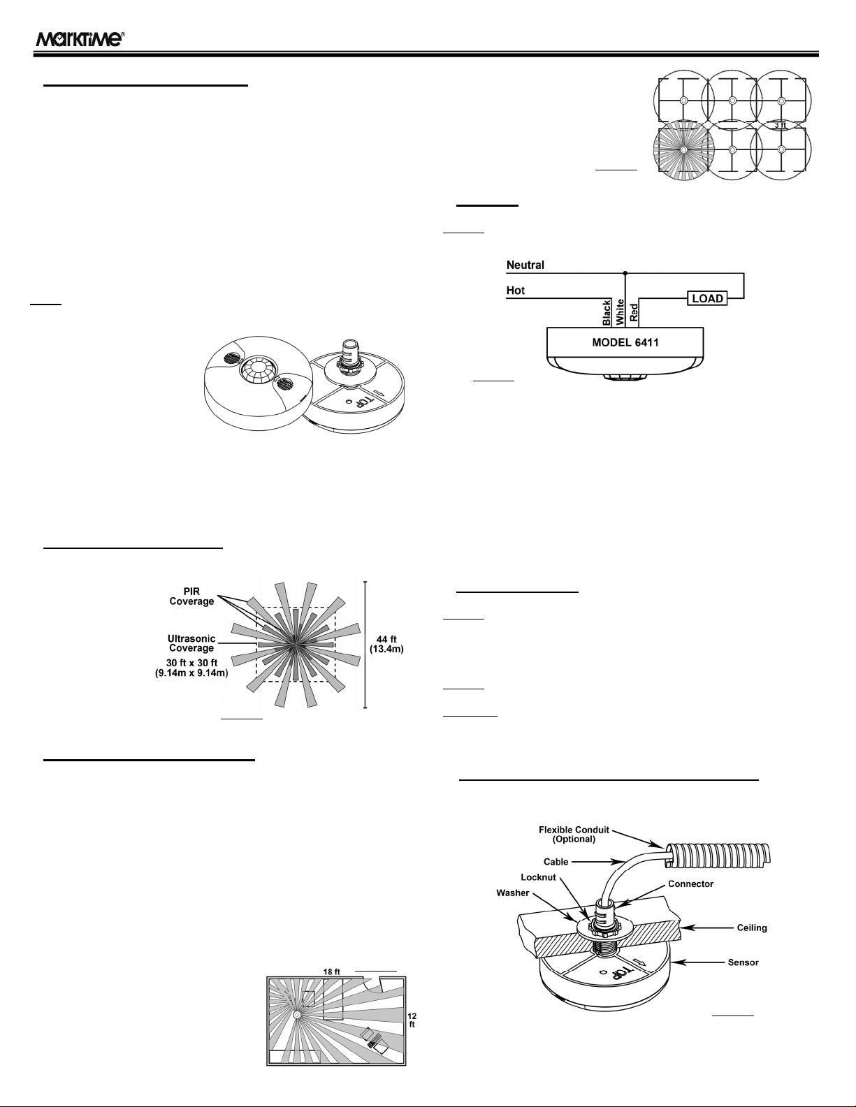
4) Attach the sensor to the round hole as shown in Figure-5.
5) Install the large washer and locknut to the threaded portion of the sensor,
and twist the locknut until the sensor is tight.
6) Connect the line voltage wires to the appropriate lead wires on the sensor
cable. (See WIRING section.)
7) Slide Flex EMT sleeve over mounting base connector if being used.
8) Adjust the settings of the sensor if required by accessing the controls on
the sensor housing (see Figure-6). See the Settings Section for customizing
the operation of the sensor.
9) Snap the front cover onto the sensor housing and restore circuit power.
NOTE:THERE IS A 45 SECOND WARM-UP PERIOD WHEN POWER IS FIRST APPLIED.
♦SETTINGS
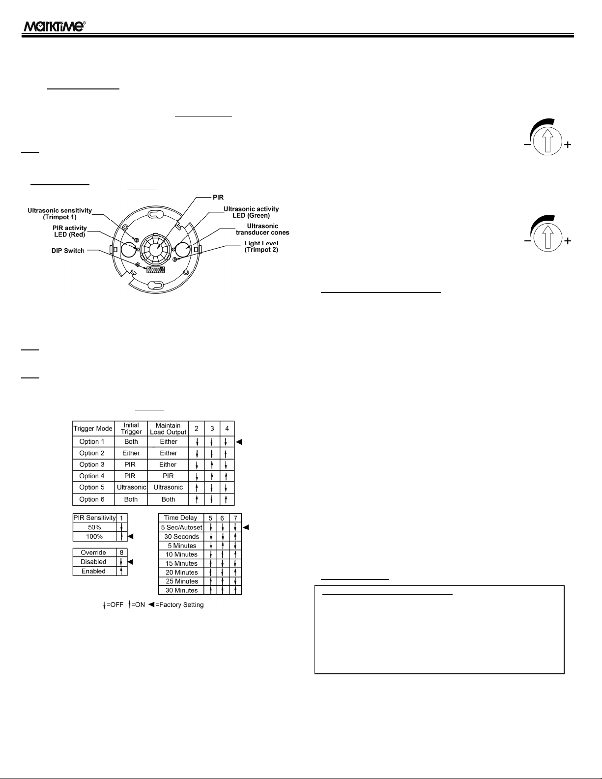
1) The 6411 sensor has 8 DIP switches under the sensor cover that can be
used to adjust the PIR sensitivity, trigger mode, time delay, & override
feature. See Figure-7 for all available DIP switch settings and defaults.
NOTE:THE SENSORS ARE PRESET AT THE FACTORY TO ALLOW FOR QUICK
INSTALLATION IN MOST APPLICATIONS.
NOTE:BEFORE MAKING ADJUSTMENTS, BE SURE OFFICE FURNITURE IS
INSTALLED, LIGHTING CIRCUITS ARE TURNED ON, AND HVAC SYSTEMS ARE IN THE
OVERRIDDEN/ON POSITION.
PIR Sensitivity Setting: Switch 1
50% - Sensor's coverage is smaller; about half of the widest range.
100% - Maximum range of the sensor's PIR coverage (1600 sq-ft).
Trigger Mode: Switches 2, 3, 4
The sensor has 6 trigger options. In the trigger mode DIP switch setting
table:
- Both: Requires motion detection by the PIR and Ultrasonic sensor.
- Either: Requires motion detection by only one technology.
- PIR: Requires motion detection by the PIR sensor.
- Ultrasonic: Requires motion detection by the Ultrasonic sensor.
Time Delay: Switches 5, 6, 7
The sensor will hold the lights on as long as occupancy is detected. The
time delay countdown starts when no motion is detected. After no motion is
detected for the length of the set time delay, the sensor will turn the lights off.
Override: Switch 8
To override all sensor functions, set to ON position.
Ultrasonic Sensitivity Adjustment, Trimpot 1
To adjust the ultrasonic sensing level, rotate the
"Ultrasonic" trimpot as needed.
- Turn towards the "+" for a larger room space.
- Turn towards the "-" to avoid false triggering in a smaller
room and if near a doorway or heat source.
Ambient Light Level Adjustment, Trimpot 2
To adjust the ambient light level (to accomodate amount of daylight entering
the room), rotate the "Light" trimpot as needed.
Turn towards the "-" if enough daylight enters the room for
it's intended use (lights will not turn on when motion is
detected).
Turn towards the "+" if lights should turn on regardless of
amount of available daylight. Range is 100Lux to Daylight.
♦TROUBLESHOOTING
Lights do not turn on with occupancy.
PIR Activity LED (red) does not flash:
1) Check that the circuit breaker or any wall switch connected to the sensor
has been turned back on.
2) Be sure that the PIR Sensitivity is set for 100% (DIP Switch 1 to ON)
3) Check all sensor wire connections.
Ultrasonic Activity LED (green) does not flash:
1) Ultrasonic sensitivity setting may need to be increased. Turn Trimpot 1
clockwise as needed.
PIR Activity LED flashes:
1) If the sensor's Light Level trimpot has been turned to the "-", the lights
may be held off by the sensor because of the available ambient light in the
coverage area. In this case, try covering the PIR Sensor lens and the PIR
Activity LED with your hand. If the lights turn on, readjust the Light Level
trimpot towards the "+" as needed for the desired operation.
2) Check all sensor wire connections.
Lights do not turn off automatically.
1) Sensor may be experiencing activations from some type of interference
such as HVAC or VAV vents. Relocate sensor if too close to these units.
2) Check all sensor wire connections.
3) Reduce ultrasonic sensitivity by turning the Trimpot 1 counterclockwise
until it only flashes when movement occurs.
4) Reduce the PIR sensitivity by setting DIP Switch 1 to OFF.
♦WARRANTY
Model 6411 360º PIR/Ultrasonic Line-Voltage Occupancy Sensor INSTRUCTIONS
THREE YEAR LIMITED WARRANTY
If this product fails because of a manufacturing defect within three years after
purchase, we will replace it at no charge. Our warranty does not cover
damage caused by accident, abuse, or misuse. We assume no further
liability with respect to the sale or use of this product.
This warranty is in lieu of all other warranties, expressed or implied, including
the warranty of merchantability. We make no warranty with respect to the
fitness of any goods for the user's particular application. This warranty gives
you specific legal rights, and you may also have other rights which vary from
state to state.
Figure-6
Figure-7
Ultrasonic
Light