Marktime 6421 User manual
♦GENERAL INFORMATION
SPECIFICATIONS:
Voltage: 24VDC
Current Consumption: 20mA
Power Supply: 6400 Power Pack
Operating Temp: 0°C to 55°C (32°F to 131°F )
Adjustable Time Delay: 5 Sec (test mode) to 30 Min
PIR Adjustment: 50% or 100% (Dip Switch 1)
Ultrasonic Adjustment: Minimum to Maximum (Trimpot 1)
Light Level Adjustment: 100 Lux - Daylight (Trimpot 2)
PIR Coverage: 1600 ft2
Ultrasonic Coverage: 1000 ft2
NOTES:- Keep these instructions available for future reference.
- Indoor use only.
DESCRIPTION:
The Model 6421, 360° Dual-Technology
Occupancy Sensor unites advanced
passive infrared (PIR) and ultrasonic
technologies into one unit. These
combined technologies help to avoid
false triggering and wasted energy.
Selectable operating modes allow the
sensor to turn a load on automatically
and keep it on as long as either or both technologies detect occupancy.
When no movement is detected after the selected time delay, the switch
automatically turns the load off.
Works well with the Model 6400 Power Pack.
♦COVERAGE PATTERN
The 6421 sensor
provides a 360°
coverage pattern. The
coverage shown in
Figure 1 represents
walking motion at a
mounting height of 9
feet. For building
spaces with lower
levels of activity or with
obstacles and barriers,
coverage size may
decrease.
♦PLACEMENT GUIDELINES
Depending upon obstacles such as furniture or partitions, the area of
coverage may be more or less than the sensing distances shown in the
coverage pattern (see Figure 1). This must be considered when planning the
number of sensors and their placement. It is also recommended to place the
sensor 4-6 feet away from air supply ducts as rapid air currents or the
differences in temperatures could cause false activations.
Mount the sensor to the ceiling. The 6421 is designed for a ceiling height of
about 8-10 feet. Mounting above or below this range will significantly affect
the coverage patterns. Be aware as you decrease the
mounting height, you decrease the range and increase the sensitivity to
smaller motions. Conversely, when you increase the mounting height, you
increase the range and decrease the sensitivity to smaller motions. At
heights of more than 12-14 feet, you may start to significantly reduce
sensitivity. As a general rule, each occupant should be able to clearly view
the sensor.
Often the best location to install a model
6421 occupancy sensor in a closed
office is off-center (see Figure 2).
Avoid placing the sensor directly in line
with an open door through which it has
a clear view out, as the sensor may
detect people walking by.
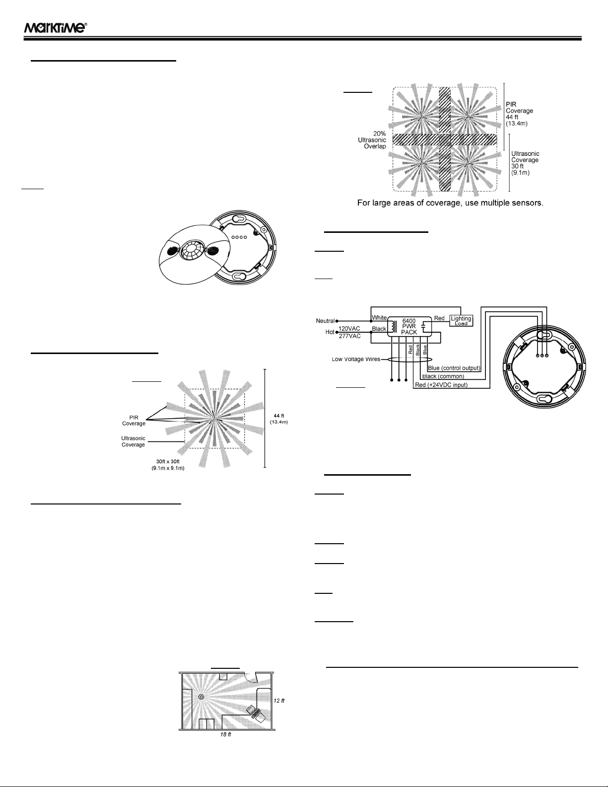
For open office area coverage, install multiple sensors so that there is an
overlap with each adjacent sensor's coverage area. (see Figure 3)
♦WIRING DIAGRAM
CAUTION:BE SURE TO DISCONNECT POWER FROM THE CIRCUIT BREAKER
BEFORE WIRING!
NOTE:EACH 6400 POWER PACK CAN SUPPLY POWER FOR UP TO SIX 6421
SENSORS. WHEN USING MORE THAN SIX SENSORS, MULTIPLE POWER PACKS ARE
REQUIRED.
Standard Wiring (Low Voltage Connections):
RED --- +24VDC
BLACK --- Common
BLUE --- Control Output
♦INSTALLATION
CAUTION:INSTALLATION BY A LICENSED ELECTRICIAN IS RECOMMENDED.
INSTALLATION AND USE OF THIS EQUIPMENT SHOULD BE IN ACCORDANCE WITH
PROVISIONS OF THE U.S. NATIONAL ELECTRICAL CODE, APPLICABLE LOCAL CODES,
AND PERTINENT INDUSTRY STANDARDS.
CAUTION:USE THIS DEVICE WITH COPPER WIRE ONLY.
CAUTION:IMPROPER WIRING CAN CAUSE DAMAGE TO THE POWER PACK,
LIGHTING SYSTEM, OCCUPANCY SENSOR(S), AND OTHER CONTROL DEVICES.
NOTE:MOST APPLICATIONS REQUIRE UL LISTED, 18-22 AWG, 3-CONDUCTOR,
CLASS 2 CABLE FOR LOW-VOLTAGE WIRING.
WARNING: TO AVOID FIRE, SHOCK, OR DEATH, TURN OFF POWER
AT CIRCUIT BREAKER OR FUSE AND TEST THAT POWER IS OFF
BEFORE WIRING SENSORS OR POWERPACKS!
1) Verify power has been turned off at the circuit breaker.
2) Refer to the WIRING DIAGRAM & PLACEMENT GUIDELINES sections
for planning and laying out the low-voltage wiring, power pack(s), and
sensor(s).
3) Pull the low-voltage wires from the power pack into the octogonal junction
box through the conduit knockout (See Figure 5).
4) Connect the low-voltage wires to the appropriate wires on the sensor.
5) Loosen the appliance mounting screws attached to the octogonal junction
box.
6) Align the sensor in the junction box so that the mounting screws on the
box line up with the slotted holes on the sensor's housing.
Model 6421 Low-
V
olta
g
e Occu
p
anc
y
Sensor - Dual Technolo
gy
INSTRUCTIONS
BX1266A, 02/17/14
Figure 2
Figure 1
Figure 3
Figure 4

7) Push the sensor up into
the junction box carefully
and twist it so that the
mounting screws are
seated in the slots.
8) Tighten the two screws
to secure the sensor to the
junction box.
9) Adjust the settings of the
sensor if required by
accessing the controls on
the housing (see Figure 6).
See the Settings Section for
customizing the
performance of the sensor.
NOTE:THE SENSORS ARE PRESET AT THE FACTORY TO ALLOW FOR QUICK
INSTALLATION IN MOST APPLICATIONS.
10) Snap the front cover onto the sensor housing and restore circuit power.
NOTE:THERE IS A 45 SECOND WARM-UP PERIOD WHEN POWER IS FIRST APPLIED.
♦SETTINGS
1) The sensor has 8 DIP
switches under the cover that
can be used to adjust the PIR
sensitivity, time delay, and
override & trigger mode feature
settings. See Figure 7 for all
available DIP switch settings.
PIR Sensitivity Setting:
Switch 1
50% - Sensor's coverage is
smaller; about half of the widest
range.
100% - Maximum range of the
Sensor's PIR coverage (1,600
sq-ft).
Trigger Mode: Switches 2, 3, 4
The Sensor has 6 triggering options; set with DIP switches 2, 3, and 4.
In the DIP Switch Setting table (Figure 7):
●Both - Requires motion detection by the PIR and Ultrasonic sensors.
●Either - Requires motion detection by one or the other sensor type.
●PIR - Requires motion detection by only the PIR sensor.
●Ultrasonic - Requires motion detection by only the Ultrasonic sensor.
Time Delay: Switches 5, 6, 7
The sensor will hold the lights on as long as occupancy is detected. The
time delay countdown starts when no motion is detected. After no motion is
detected for the length of the set time delay, the sensor will turn the lights off.
Override: Switch 8
To override all sensor functions, set to ON position.
Ultrasonic Sensitivity Adjustment
To adjust the ultrasonic sensitivity, adjust the "Ultra" trimpot
as needed. Turn towards the right for greater room space.
Turn towards the left to reduce false triggering in a smaller
room and near a door or heat source.
Ambient Light Level Adjustment
To adjust the ambient light level (to accomodate amount of
daylight entering the room), adjust the "Light" trimpot as
needed. Turn towards the right if enough daylight enters
the room for it's intended use. Turn towards the left if the
daylight in the room isn't enough. Range is 100Lux to Daylight.
♦TROUBLESHOOTING
Lights to not turn on with occupancy.
Both LEDs do not flash:
1) Check that the circuit breaker has been turned back on.
2) Check all sensor and power pack wire connections.
3) Check for 24VDC input to the sensor between the red and the black low-
voltage wires.
●If 24VDC is present, replace the sensor.
●If 24VDC is not present, check the high-voltage connections to the power
pack.
●If high-voltage connections are good, and high-voltage is present at the
proper value, replace the power pack.
Red LED does not flash:
1) If occurs when sensor is initially powered up, wait 45 seconds for the
warm-up period before the LED is active.
2) Make sure PIR sensitivity is set to 100% (DIP Switch 1)
Green LED Does not flash:
1) Ultrasonic sensitivity setting may need to be increased. Turn clockwise
as needed.
Lights to not turn off automatically.
Green LED flashes:
1) Reduce ultrasonic sensitivity by turning count-clockwise until it only
flashes when movement occurs.
Red LED flashes:
1) Reduce PIR sensitivity by setting to 50% (Dip Switch 1).
Lights do not turn off:
1) Check all sensor and power pack wire connections.
2) Disconnect power pack blue wire.
●If lights do not turn off, check power pack wiring and replace the power
pack if necessary.
●If lights turn off, the problem may be the sensor or wiring between the
sensor and power pack.
3) Reconnect the blue wire.
4) Turn sensitivity and time delay to minimum, and allow the sensor to time
out.
●If lights turn off, the sensor is working properly. Adjust sensitivity and time
delay for the sensor.
●If lights do not turn off, check wiring between the sensor and power pack.
●If wiring is correct, replace the sensor.
Unwanted Sensor Activations (LED flashes).
Possible Causes:
1) Sensor located too close to HVAC or VAV vents with heavy air flow.
2) The ultrasonic sensitivity may be too high.
3) The PIR sensitivity may be set too high.
Possible Solutions:
1) Relocate the sensor.
2) Reduce the ultrasonic sensitivity as needed.
3) Partically mask the PIR lens to reduce coverage.
♦WARRANTY
THREE YEAR LIMITED WARRANTY
If this product fails because of a manufacturing defect within three years after purchase,
we will replace it at no charge. Our warranty does not cover damage caused by accident,
abuse, or misuse. We assume no further liability with respect to the sale or use of this
product.
This warranty is in lieu of all other warranties, expressed or implied, including the
warranty of merchantability. We make no warranty with respect to the fitness of any
goods for the user's particular application. This warranty gives you specific legal rights,
and you may also have other rights which vary from state to state.
Model 6421 Low-
V
olta
g
e Occu
p
anc
y
Sensor - Dual Technolo
gy
INSTRUCTIONS
Ultra
Light
Figure 5
Figure 6
Figure 7
Other Marktime Accessories manuals


