Maro MA Series User manual

1
MARO OPERATING MANUAL
INCLUDING: OPERATION, INSTALLATION & MAINTENANCE
RELEASED: 1.4.2021
3” MARO MA Series Metallic DIAPHRAGM PUMP
READ THIS MANUAL CAREFULLY BEFORE INSTALLING, OPERATING OR SERVICING THIS EQUIPMENT. It is the responsibility of the employer to
place this information in the hands of the operator. Keep for future reference. Failure to comply with the recommendations stated in this
manual can cause serious injury, damage the pump and void factory warranty.
Compound
Optimum
Temperature Main Applications / Chemical Compatibility
Neoprene 10 to 54 C General purpose diaphragm
(non-aggressive applications -- water-based slurries, well water or sea
water)
50 to 130 F
Buna-N 10 to 60 C
50 to 140 F
Petroleum/oil-based fluids (leaded gasoline, fuel oils, non-synthetic
hydraulic oils, kerosene, turpentine, motor oils)
Santoprene 10 to 100 C
50 to 212 F
Low
er
cost
alternative to
PTFE
in many acidic and caustic applications
such as sodium hydroxide, sulfuric or hydrochloric, At a cost comparable
to neoprene.
PTFE
10 to 100
C
50 to 212 F Aggressive chemicals and solvent but low abrasion resistance
PUMP DATA
Maximum Capacity: 890 l/min (236 gpm)
Air Inlet Connection: ¾” BSP (F)
Fluid Inlet/Outlet Connection: 3” BSP (F) or NPT (F)
Max. Working Pressure: 8.3 bar (120psi)
Suspended Solids Max. Dia.: 9 mm (3/8”)
Max. Dry Suction Lift: 5.8 m (19 ft)
Shipping Weight: 50 Kg (110 lbs) AL Pump
97 Kg (213 lbs) CI Pump
101 Kg (223 lbs) SS Pump

2
GENERAL DESCRIPTION
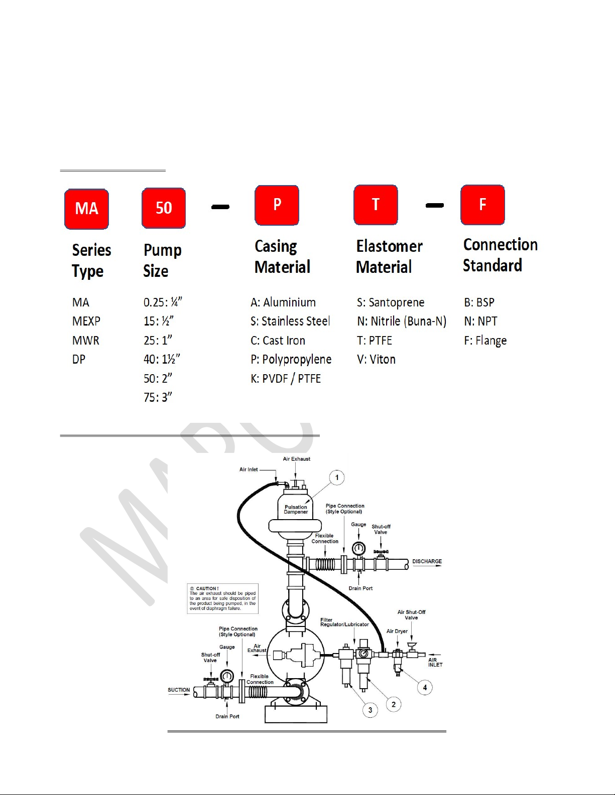
Air operated double diaphragm pumps utilize a pressure differential in the air chambers to alternately
create suction and positive fluid pressure in the fluid chambers. Ball Check insure the positive flow of fluid.
Pumping cycling will begin as air pressure is applied and it will continue to pump and keep up with
demand. It builds a maintain line pressure and will stop cycle once maximum lune pressure is reached or
dispensing device closed and resume pumping as needed.
OPERATING AND SAFETY PRECAUTIONS
READ, UNDERSTAND AND FOLLOW THIS INFORMATION TO AVOID INJURY AND PROPERTY DAMAGE.
for your own safety
BEFORE using or servicing your pump, please make sure to wear the proper clothing, eye protection
and follow standard safety procedures when handling corrosive or personally harmful materials.
To avoid danger and risk to yourself and others always use only genuine MARO parts.
warning
Fire or explosion can result when handling flammable liquids. The pump, piping, valves, containers or
other miscellaneous equipment must be grounded.
When used for toxic or aggressive fluids, the pump should always be flushed clean prior to
disassembly. User must ensure chemical compatibility, and any pressure / temperature limits are not
exceeded.
NB: Temperature and pressure limits for diaphragms and other components are noted in the
technical section of this manual.
caution
The pump is pressurized internally with air during operation. Before commencing any work or
maintenance on the MARO Pump, shut off the compressed air line, safely bleed the pressure,
and disconnect the air-line from the pump. The product discharge line may be pressurized
and must be safely bled off its pressure. Never place your hands near the suction inlet as the
powerful suction can cause serious bodily injury.
If the pump is not used for more than two (2) days, care must be taken when restarting. If in
any doubt, remove pump from line and flush with a suitable cleaner. Solidified deposits
within the pump may cause damage to the diaphragms.
Before starting or resuming pump operation after maintenance, inspect all fasteners are
correct, check for looseness caused by gasket creep. Re-torque all fasteners to prevent
leakage. Follow recommended torques stated in this manual. Ensure correct fitting of Inlet /
Outlet connections. Crossed threads or over tightening of connections will result in leaks.
Quick action/release connections are not recommended. If their use is unavoidable, the
levers must be locked to avoid them being forced apart in a hazardous manner. In case of
excess vibration, MARO recommend fitting a Pulsation Dampener to remove effects of pulse
actions from pump operation. Flexible connections can be used, but must be kept to a
minimum length necessary to avoid sharp flexing or straining movements.
EXCESSIVE AIR PRESSURE. Can cause pump damage, personal inquiry or property damage.

3
It always good to have lubricated air (lubrication oil must be SAE 5 or 10 with just 10 minutes
a drop)
If lubricated air is present, make sure that it is compatible with the O-rings and seals in the
center section of the pump
A filter capable of filtering out particles larger than 50 microns should be used to this air
supply.
IDENTIFICATION CODE
SUGGEST DIAPHRAGM PUMP INSTALLATION DIAGRAM

4
PUMP CURVE
PARTS LIST

5
FLUID PART LIST

6
FLUID SECTION DISASSEMBLY
1. Remove (61) top manifolds
2. Remove (22) balls, (19) O – rings and (21) seats.
3. Remove (15) Fluid Chamber
NOTE: Only PTFE diaphragm use a primary diaphragm (7) and a backup diaphragm (8). Refer to the auxiliary view in the
Fluid Section illustration
4. Remove (14) screw, (6) washer, (7) or (7/8) diaphragms and (5) washers
NOTE: Do not scratch or mar the surface of (1) Shaft
FLUID SECTION REASSEMBLY
1. Reassembly in reverse order
2. Clean and inspect all parts. Replace worn or damaged parts with new parts as required
3. Lubricate (1) Shaft and (2) O – ring with lubricant grease O ring lube
4. Install (2) O ring on (1) Shaft
5. Be certain (7) or (7/8) diaphragm(s) align properly with (15) fluid caps before making final torque adjustment on bolt
and nuts to avoid twisting the diaphragm
6. For model with PTFE diaphragm: Item (8) Santoprene diaphragm is installed with the side marked “AIR SIDE” towards
the pump centre body. Install the PTFE diaphragm with the side marked “FLUID SIDE” towards the fluid chamber
7. Re-check torque setting after pump has been re-started and run a while
AIR AND CENTRE SECTION PART LIST

7
AIR MOTOR SECTION SERVICE
Service is divided into two parts: 1. Pilot Valve, 2 Major Valve
Air Motor section service is continued from Fluid Section repair
Inspect and replace old parts with new parts as necessary. Look for deep scratches on metallic surfaces, and nicks or
cuts in O rings
Take precautions to prevent cutting O ring upon installation
Lubricate O ring with lubricant grease
Do not over tighten fasteners, refer to torque specification block on view
Re-torque fastener following restart
PILOT VALVE DISASSEMBLY
o Remove (104) retaining ring
o Remove (123) screw and (122) O rings
o Remove (118) piston rod, (121) sleeve bushing, (119) O rings and (120) spacers from (101) centre body
o Remove (103) sleeve and (102) O rings
PILOT VALVE REASSEMBLY
o Replace two (102) O rings if worn or damaged and reinstall (103) sleeve
o Install one of the (121) sleeve bushing, (119) O rings, (120) spacers and remaining (121) bushing
o Carefully push (118) pilot rod into bushings etc. and retain on each end with the two (122) O rings, retain with (123)
screws
o Replace (104) retaining rings
MAJOR VALVE DISASSEMBLY
1. Remove (107) plate, (108 & 117) gaskets
2. On the side opposite the air inlet, push on the inner diameter (111) spool. This will force the (109) piston out. Continue
pushing the (111) spool and remove. Check for scratches and gouges
3. Reach into the air section (exhaust side) and remove (116) spacer, (115) spacers, and (113) O rings, (114) O rings, (112)
Washer, etc. Check for damaged O rings
MAJOR VALVE REASSEMBLY
1. Replace (112) washer, (114) O ring and (113) O ring onto (115) spacer and insert etc.
Note: Be careful to orient spacer legs away from blocking internal ports
2. Lubricate and carefully insert (111) spool
3. Install (117) gasket and (107) plate
4. Lubricate and install (110) packing cup and insert (109) piston into (air inlet side) cavity, the (110) packing cup lips should
point outward
5. Install (108) gasket and (107) plate
TROUBLE SHOOTING
Problem
Cause
Solution
Pump cannot start Air connected to Exhaust
Discharge piping obstructed or shut off
valve closed.
Shaft Seal failure
Diaphragm ruptured
Air Valve System malfunction
Re-connect to Air Inlet
Clean the line or open the shut
off valve
Replace New Shaft Seal
Replace Diaphragm
Check carrier for freedom of
movement and all seals in chest
assembly. Clean or replace.
Pump runs but no
discharge
Suction Line Leakage
Valve ball not seating correctly or
damaged
Suction Strainer or Line clogged
Excessive Suction Lift
Diaphragm ruptured
Check and Repair
Remove obstruction / replace
balls or seats
Clear
Shorten Suction line
Replace Diaphragm

8
Intermittent stroke rate Shaft Seal failure
Air Valve System malfunction
Over lubrication
Valve Ball obstruction or not sealing
Replace New Shaft Seal
Check carrier for freedom of
movement and all seals in chest
assembly. Clean or replace.
Clean the Air Valve System &
Shaft bushing.
Remove obstruction / replace
balls or seats
Fluid discharge from air
exhaust
Loose Outer Piston
Diaphragm ruptured
Re-Torque to manual
specification
Replace Diaphragm
Erratic Flow Diaphragm ruptured one side
Suction Line Leakage
Air Valve System malfunction
Shaft Seal failure
Valve ball not seating correctly or
damaged
Replace Diaphragm
Check & Repair
Check carrier for freedom of
movement and all seals in chest
assembly. Clean or replace.
Replace New Shaft Seal
Remove obstruction / replace
balls or seats
DIMENSIONAL DATA
NOTICE: Limited Warranty, General Terms & Conditions
Every MARO Pump is manufactured to meet the highest standards of quality. Every pump is functionally tested to ensure integrity of operation. MARO
Pump warrants that pumps, accessories and parts manufactured by MARO Pump to be free from defects in material and workmanship for a period of
twelve (12) months from date of installation or eighteen (18) months from date of manufacture, whichever comes first. Products, parts or accessories
manufactured by others but supplied by MARO Pump are covered only to the extent of the original manufacturer’s warranty for replacement or repair.
Failure due to normal wear and tear, improper storage or handling, un-authorized modification, misapplication or abuse is specifically excluded from
this warranty. MARO Pump shall not be liable for any and all consequential damage or expense arising from the use or misuse of its products. In any and
all events, manufacturer’s liability shall not exceed the purchase price of the product and/or accessories. All decisions as to the cause of failure are the
sole determination of MARO Pump.
THE WARRANTY / LIABILITY AS SET FORTH ARE EXCLUSIVE AND IN LIEU OF ALL OTHER WARRANTIES AND LIABILITIES EXPRESSED OR IMPLIED,
INCLUDING WARRANTY OF MERCHANTABILITY AND FITNESS FOR PURPOSE.
In case of doubt or enquiries or ensure, please contact our Technical Service dept.: enquiry@maropump.com
Table of contents
Popular Water Pump manuals by other brands

Triton
Triton T22i Installation and operating instructions

Homa
Homa Saniquick A Installation and operation instruction manual

Beckett
Beckett FC1200 owner's manual

Pulsafeeder
Pulsafeeder DC6 Installation & operating instructions

Lincoln
Lincoln SKF FlowMaster II A Series User and maintenance instructions

Lorentz
Lorentz PSk Series MANUAL FOR INSTALLATION, OPERATION, SERVICE

Aspen
Aspen mini orange manual

Valley Industries
Valley Industries EVERFLO EFHP1011-QA owner's manual

Ozito
Ozito CPPAS-800 instruction manual

Goulds Pumps
Goulds Pumps J5S Installation, operation and troubleshooting manual

teel
teel 4RJ47 Operating instructions & parts manual

Regulus
Regulus CSE TV ZV G 1F Installation and operation manual