manuals.online logo
Brands
  1. Home
  2. •
  3. Brands
  4. •
  5. FLOJET
  6. •
  7. Water Pump
  8. •
  9. FLOJET G70C Series Owner's manual

FLOJET G70C Series Owner's manual

4.58
(116)
0.25
(6.4
5.2
(134)
Air Exhaust
Muffler
2.20
(56)
1.84
(47)
0.92
(23)
0.71
(19)
3.21
(82)
4.52
(115) 5.81
(148)
Fluid OutFluid In
Air Inlet
PRODUCT DATA
Pump D sign ............................................Double Diaphragm
W tt d Parts ............................................................................
......
Body and Check Valves
................................Polypropylene
......Diaphragm ....................................................Kalrez®6190
........Check Valve Seals..................................Viton®Extreme™
......Springs ..............................................................Hastelloy®
Ports ......................................................Air nlet 1/4” (6.3 mm)
Liquid nlet 3/8” (9.5 mm) - 1/2” (12.7 mm) - 3/4” (19.1 mm)
Liquid Outlet 3/8” (9.5 mm) - 1/2” (12.7 mm) - 3/4” (19.1 mm)
N t W ight ....................................................1.2 lbs. (0.54kg)
PERFORMANCE SPECIFICATIONS
Liquid T mp ratur Rang
:
............40 - 120°F (4.4 - 48.9°C)
Air ........................ nlet Pressure: ......20 - 100 PS (1.4 - 6.9 Bar)
............................ nlet Temperature: ....40 - 130°F (4.4 - 54.4°C)
..............................Relative Humidity: ..................................0 - 1%
Environm nt T mp ratur : ..................40 - 130°F (4.4 - 54.4°C)
Priming ................Dry: ..............................................15 ft. (4.5 m)
..............................Wet:................................................20 ft. (6.1m)
Flow Rat ............................................Up to 5.0 GPM (18.9 LPM)
Nois L v l..........Max ..........................................................87dB
NOTE: Pump Operation must remain within tolerances specified above
Kalrez®and Viton®Extreme™ are trademarks or registered trademarks of DuPont Performance
Elastomers. DuPont is a registered trademark of DuPont and its affiliates.
Hastelloy®A registered trademark of Haynes nternational, nc.
John Guest®A registered trademark of John Guest nternational, Limited.
DESCRIPTION
FLOJET ndustrial G70C Pumps are designed for
general commercial and industrial applications. These
pumps are constructed from a selection of materials for
handling a broad range of chemicals.
Allow d fluids for Not Allow d fluids for
Kalr z®parts Kalr z®parts
Lubricating Oils, Halogenated Solvents
Hydraulic Oils,
Vegetable Oils,
Alcohols, Keytones,
Aromatic Hydrocarbons,
Aliphatic Hydrocarbons,
Diluted Acids, Alkalis,
Soaps with solvents,
Automotive brake fluid,
Acetones, Ethanol, inks.
MARKS AND GENERAL INFORMATION
n complicance with the 94/9/CEE standards, the pumps carry the
following identification marks:
II 2G c IIB TX
: safety symbol to Din 40012
II 2G: surface equipment for use in areas with the
presence of gases, vapors or mists in addition to
clouds of combustible dust in the air that occur
occasionally during normal operation (EN 1127-1
par. 6.3), both in external and internal areas
(ZONE 1).
c: protection by constructional safety (EN 13463-5)
IIB: Excluding the following products hydrogen,
acetylene, carbon disulphide.
TX: Class of admitted temperatures. The processed
fluid temperature value must fall within such class
range and the user must comply with the
instructions contained in the manual and with
the current laws. Furthermore, the user must take
into account the ignition point of the gases, vapors
and mists in addition to clouds of combustible
powder in the air existing in the area of use.
G70C Serie
Indu trial Air Driven Pump
DIMENSIONAL DRAWING
nches (millimeters)
INSTALLATION & OPERATION
INFORMATION FOR MODELS G70C XXX
Pressure PSI (BAR)
Flow Rate in GPM (1/min.)
Kalrez¨Diaphragm with 1/2Ó Ports
PERFORMANCE: KALREZ®WITH 1 2” PORTS
Air Flow Rate (SCFM)
1.0
1.3
1.7
2.2
Air In (PSI)
40
60
80
100
Note: Refer to page 4 for
General Safety nformation.
MOUNTING
The FLOJET G70C self-priming pump should be mounted in a
dry and adequately ventilated area. This pump can be mounted
several feet from the tank, above or below the fluid level. For
most applications, no more than 4 feet above the fluid level is
recommended. Note: This is not a subm rsibl pump.
Secure Pump to desired fixture by inserting screws through the
rubber grommets in the baseplate of the pump. Ports must b
facing down. The pump must be protected by a housing able
to withstand the impact of a steel half ball of 25mm with a mass
of 1Kg and an energy of 7J. Refer to EN 13463-1 Par 13 for
further details.
HOSE CONNECTIONS
Liquid n - Use 3/8”, 1/2”, or 3/4” .D. reinforced hose or
equivalent. Avoid sharp bends that could restrict flow or
cause hose to collapse under vacuum.
Liquid Out - Use 3/8”, 1/2”, or 3/4” .D. reinforced hose for
discharge tube. 3/4” .D. hose must use 90° elbows when
using large muffler.
Air n - Make sure air regulator is set at zero. Use reinforced
1/4” .D. hose. Connect “Air n” to air supply fitting on
regulator. f pumps are installed in an enclosed area, it is
recommended to connect a hose to the air discharge port
(exhaust) and vent air to atmosphere (Requires small
exhaust port PN# 20756103B not included).
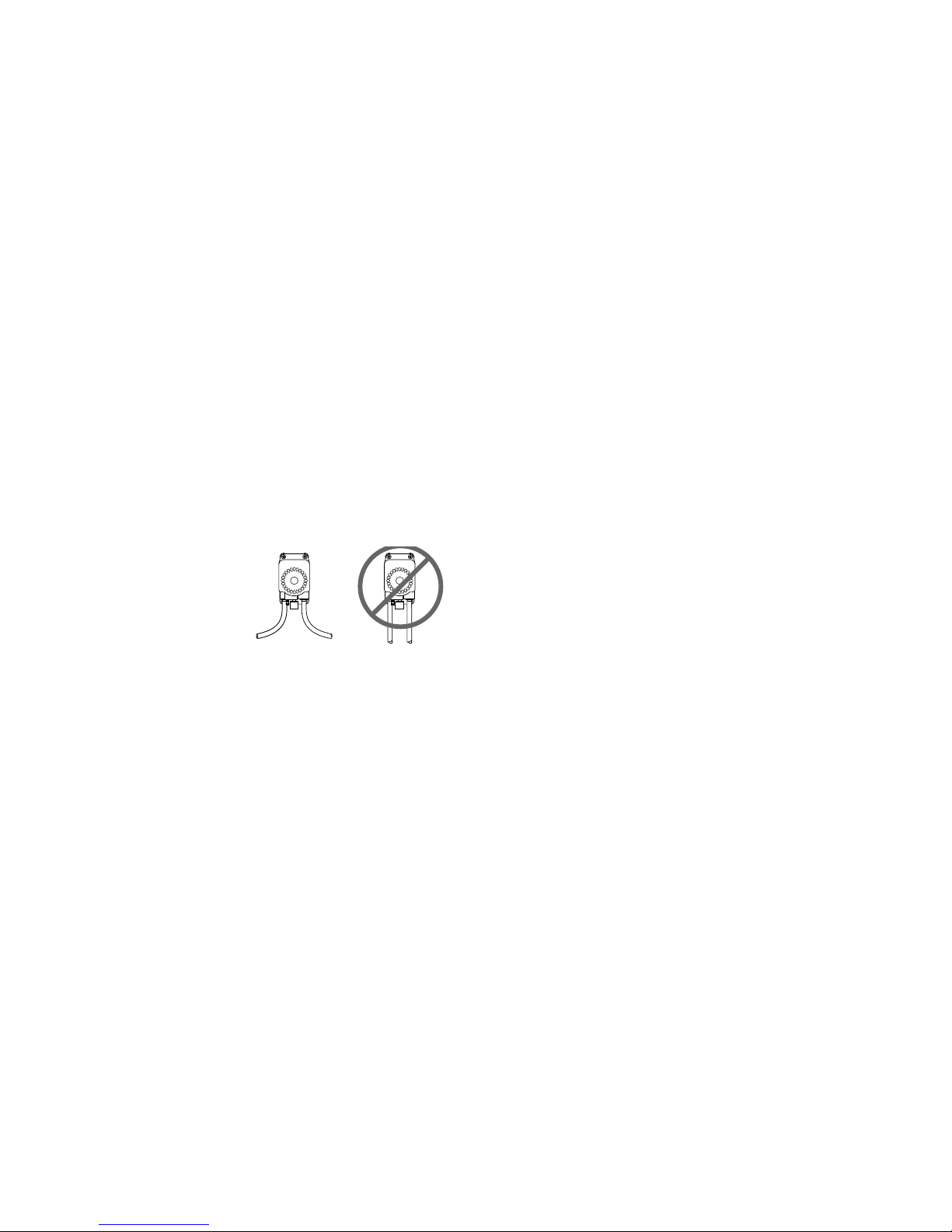
PLUMBING
Use a flexible hose to avoid
excess stress on pump ports.
DO NOT crimp or kink hose.
All hose should be the same
size as the pump port fittings.
All fittings and hose must be
compatible with fluid being
pumped. t is recommended to use plastic fittings only.
The use of check valves in the plumbing system could
interfere with the priming ability of the pump. f unavoidable,
check valves in the pumping system must have a cracking
pressure of 2 PS or less.
Use a minimum 40 mesh strainer or filter in the tank or pump
inlet line to keep large foreign particles out of the system.
Liquid inlet port must be equal to or larger than the liquid
outlet port.
OPERATION
At start-up, regulate air pressure to desired setting. For
most installations 20 PS (1.4 bar) inlet will be adequate,
although DO NOT go below 20 PS . Pump will operate
according to air supply. Flow and pressure can be adjusted
by increasing or decreasing air pressure to accommodate
varying product viscosities, length of lines or other
installation conditions. Review flow curves located on page
1 for further assistance. High viscosi ty fluids and hose
length will limit priming distance.
Compressors must have dryers and/or a water separator in
the air distribution system. Pumps that fail due to water in
the air chamber will not be covered under the limited
warranty.
Plastic air inlet ports do not have a check valve. Prior to
cleaning or servicing, purge the pump by carefully tilting the
pump so ports are facing up and remove suction line from
source. Turn air off and disconnect air inlet line. (Standard
brass air inlet ports have a check valve).
DISASSEMBLY PROCEDURE
First, remove inlet air line, muffler and suction/discharge
line from the pump. This is accomplished by using a flat-
bladed screwdriver to slide the retaining clips away from the
air inlet, muffler and suction/discharge fittings and pulling
the fittings away from the pump body. Now remove the muf-
fler by sliding the retaining clip away from the muffler base
and pulling the muffler out of the pump body.
Using a Phillips screw driver remove the seven (7) screws
from the front end cap followed by the (7) screws from the
rear end cap. With the front end cap facing up and the rear
end cap facing down on the workbench, position a flat blad-
ed screw driver into the slot located above the muffler port
and just below the pad marked Air/C02and lift off the front
end cap. The rear end cap can be removed by placing the
flat bladed screwdriver under the fully opened port retaining
clip and lifting off.
Note the position of the suction and discharge valves before
removing them from the pump body. The first diaphragm is
removed from the pump shaft by unscrewing in a counter
clockwise direction. The second diaphragm is removed by
placing the flat tip of a screwdriver into the exposed slot at
the end of the pump shaft and unscrewing the diaphragm
from the shaft. To remove the flange housing, place the tip
of the flat bladed screw driver into the air bleed hole on the
lower side of the flange housing and lift up the lower end
separating the flange housing from the pump body.
The slide valve assembly and pump shaft can be removed
by simply pulling them from the pump body. The pump shaft
then can be removed from the slide valve yoke assembly.
REASSEMBLE PROCEDURE
Assemble the slide valve and pump shaft with the yoke
placed between the (2) bumpers on the pump shaft. nstall
the slide valve/pump shaft assembly into the pump body
making sure the O-rings in the slide valve are in place. To
install the flange housing, prelube the o-ring with Parker
Super “O” Lube and install on flange housing and place
housing over the pump body aligning the flange housing
with the pump body ribs pressing it into place.
nstall the first diaphragm and O-ring on to the pump shaft
by threading on to shaft using a flat blade screwdriver to
hold the pump shaft until the diaphragm is tight. nstall the
second diaphragm and O-ring on to the pump shaft turning
clockwise until tight.
nstall the suction valves with springs facing into the pump
body and the discharge valves with the springs facing out.
See arrows on pump rear end cap below suction and
discharge ports.
nstall the port retainer clips (large) into the pump end cap
(mounting base) and install the seven (7) Phillips screws
into pump body and cross tighten until snug and then cross
torque to 22-24 inch pounds. nstall port retaining clips
(small) into the pump body with tabs facing out. Position the
front end cap and install the seven (7) Phillips screws into
pump body and cross tighten until snug and then cross
torque to 22-24 inch pounds.
nstall the muffler in the center port by pushing it in and
sliding the retainer clip into place. nstall the suction and
discharge ports and the air inlet port fitting and slide the
retainer clips in place. Check for leaks.
FLEXIBLE
HOSE
RIGID
PIPE
K y Part No. D scription Qty
1 20740122A Kit, Check Valve, Assy., Polypropylene
Viton®Extreme™, Hastelloy®4
2 21000661A Kit, Diaphragm, Kalrez®2
3 20751002A Kit, Shaft & Slide Valve Assy. 2
4 xxxxxxxxxxA Kit, Flange & Housing Assy. w/“O” Ring 2
5 xxxxxxxxxxA Kit End Caps 2
K y Part No. D scription Qty
6 20758200A Kit Hardware - ncludes
Screws #10 x 1.5” Hi Low 14
Retainer Clip Small 2
Retainer Clip Large 2
Exhaust Port (Port x 1/4” HB) 1
Exhaust Muffler 1
7 20132000 Kit, Grommets 4
MODEL G70C SERIES EXPLODED VIEW
MODEL NUMBERING MATRIX
Part No. D scription Qty
20381100 1/2" HB, 90° Elbow 2
20381101 3/4" HB, 90° Elbow 2
21000663 1/2" OD John Guest®2
21000664 3/8" OD John Guest®2
01510 000 1/4” HB, Straight Brass (Air n) Buna O-Ring 2
20325033 1/4” HB, Straight Plastic (Air n) Buna O-Ring 2
20756103B Air Exhaust Port x 1/4” HB, O-ring 12
Polypropylene Viton®
G70C PORT FITTINGS (All liquid fittings include Viton®Extreme™ for O-ring.)
Part No. D scription Qty
20381093 10/13mm HB, 90° Elbow 2
20381094 1/2" NPT, Male, Straight 2
20381095 3/8" NPT, Male, Straight 2
20381096 10/13mm HB, Straight 2
20381097 3/4" HB, Straight 2
20381099 1/2" HB, Straight 2
For a complete port fitting list please request form No. F100-112.
GENERAL SAFETY INFORMATION
Follow all safety codes and the Occupational Safety and
Health Act (OSHA).
These User nstructions contain specific safety markings
where non-observance of an instruction would cause hazards.
The specific safety markings are:
This symbol indicates safety instructions where non-compliance
would affect personal safety and could result in serious injury.
This symbol indicates safety instructions where non-
compliance will involve some risk to safe operation and personal
safety and would damage the equipment and or property.
Do NOT pump Gasoline or flammable fluids with flash
point below 98°F (37°C) Explosion or serious injury may occur.
ncompatible fluids may cause premature failure of the
pump. t is the customer’s responsibility to ensure that
fluids are compatible with pump materials.
f used with C02or N2 be sure the area is well
ventilated.
f pump is to be used in high flow, low pressure
applications, adjust air pressure to 20 PS (1.38 bar) above
discharge pressure.
Do NOT Exceed 100 PS (6.9 bar) Air nlet
Pressure.
Continuous operation above 120°F (48.9°C)
will reduce pump life.
nlet air must be dry and oil free - use an air/oil
filter and air dryer.
Mount with ports facing down.
To Reduce the risk of static sparking, ground the pump
and all other equipment used or located in the pumping
area. Check your local electrical code for detailed
grounding instructions for your area and type of equipment.
TROUBLESHOOTING CHART
Symptom Possibl Caus (s) Corr ctiv Action
Pump will not start (stalls) 1. nadequate air supply (20 PS Min.) 1. ncrease air inlet pressure
2. Contaminated air supply 2. An air dryer might be required
3. Ruptured diaphragm (2) 3. Replace diaphragm (2)
4. Check shuttle valve for wear (11) 4. Replace shuttle valve if necessary (11)
Pump runs, but no fluid 1. A leak or break in the product inlet line 1. Replace product line
2. A leak or break in the product discharge line 2. Replace product line
Pump leaks through exhaust port 1. Leak at upper exhaust port o-ring (13) 1. Replace exhaust port (13)
2. Shaft seal o-rings damaged or worn 2. Replace shaft seal o-rings
3. nadequate slide lubrication 3. Replace with shuttle valve kit
Flow rate is low 1. Tubing or hose is damaged or blocked 1. Clean or replace
2. Check viscosity of medium being pumped 2. Reduce viscosity of medium, increase
hose diameter or contact factory for
recommendation
3. Check valves not seated correctly (6) 3. Reinstall check valves (6)
Pump leaks 1. Ruptured or worn out diaphragm (2) 1. Replace diaphragm (2)
2.
Pump housing screws not torqued adequately
2. Torque screws to 20 in lb
C
FLOJET warrants this product to be free of defects in
material and/or workmanship for a period of one year after
purchase by the customer from FLOJET. During this one
year warranty period, FLOJET will at its option, at no charge
to the customer, repair or replace this product if found
defective, with a new or reconditioned product, but not to
include costs of removal or installation. No product will be
accepted for return without a return material authorization
number. All return goods must be shipped with
transportation charges prepaid. This is only a summary of
our Limited Warranty. For a copy of our complete warranty,
please request Form No. 100-101.
RETURN PROCEDURE
Prior to returning any product to FLOJET, call customer
service for an authorization number. This number must be
written on the outside of the shipping package. Place a note
inside the package with an explanation regarding the
reason for return as well as the authorization number.
nclude your name, address and phone number.
WARRANTY
When using high pressure gas tanks make sure a
secondary regulator is used to avoid accidental damage to
pump.
Do not clean or service FLOJET pumps,
hoses or valves while the system is pressurized.
This is not a submersible pump - use only in
dry environments.
PREVENTIVE MAINTENANCE TIPS
Tips to help prolong your pump’s life.
• f pumping liquid other than water, pump should be
flushed with water (if applicable) after every use.
•
Before freezing conditions occur, pump must be liquid free.
• f mounting pump in an outdoor environment, shield
pump from environmental extremes (i.e. sunlight, water
from washdown spray, rain, etc.). Avoid high heat and
humid installations.
• When using an air compressor, use an inline air dryer
(PN# FJ520B) before the pump to limit water build-up.
CAUTION
CAUTION
CAUTION
CAUTION
CAUTION
CAUTION
CAUTION
CAUTION
For more information visit us
online at www.flojet.com

Other FLOJET Water Pump manuals

FLOJET R4515-743 User manual

FLOJET

FLOJET R4515-743 User manual

FLOJET 2100-12 User manual

FLOJET

FLOJET 2100-12 User manual

FLOJET N5100-010 Guide

FLOJET

FLOJET N5100-010 Guide

FLOJET G257 Series Guide

FLOJET

FLOJET G257 Series Guide

FLOJET 2125 Series User manual

FLOJET

FLOJET 2125 Series User manual

FLOJET 02840100A Operating and installation instructions

FLOJET

FLOJET 02840100A Operating and installation instructions

FLOJET 3426 series User manual

FLOJET

FLOJET 3426 series User manual

FLOJET 03526-144 User manual

FLOJET

FLOJET 03526-144 User manual

FLOJET 4105 Series User manual

FLOJET

FLOJET 4105 Series User manual

FLOJET 18555-000 User manual

FLOJET

FLOJET 18555-000 User manual

FLOJET R3526144 User manual

FLOJET

FLOJET R3526144 User manual

FLOJET N5000 User manual

FLOJET

FLOJET N5000 User manual

FLOJET Triplex Diaphragm 3426 Series User manual

FLOJET

FLOJET Triplex Diaphragm 3426 Series User manual

FLOJET 4300 Series User manual

FLOJET

FLOJET 4300 Series User manual

FLOJET quad II diaphragm 4125 series User manual

FLOJET

FLOJET quad II diaphragm 4125 series User manual

FLOJET 4325 Series User manual

FLOJET

FLOJET 4325 Series User manual

FLOJET N5100 Series Guide

FLOJET

FLOJET N5100 Series Guide

FLOJET BevJet Compact User manual

FLOJET

FLOJET BevJet Compact User manual

FLOJET G-57 Series Installation instructions

FLOJET

FLOJET G-57 Series Installation instructions

FLOJET N5000 Series Operation manual

FLOJET

FLOJET N5000 Series Operation manual

FLOJET G573 User manual

FLOJET

FLOJET G573 User manual

FLOJET 4305-144 User manual

FLOJET

FLOJET 4305-144 User manual

FLOJET G56 User manual

FLOJET

FLOJET G56 User manual

FLOJET R3B21 Series User manual

FLOJET

FLOJET R3B21 Series User manual

Popular Water Pump manuals by other brands

Pfeiffer Vacuum TPH 2301 P operating instructions

Pfeiffer Vacuum

Pfeiffer Vacuum TPH 2301 P operating instructions

MCDonald 710SSDEA installation instructions

MCDonald

MCDonald 710SSDEA installation instructions

Grundfos UPM3 instructions

Grundfos

Grundfos UPM3 instructions

DeatschWerks DW65a installation guide

DeatschWerks

DeatschWerks DW65a installation guide

ARVEN KONTRACT TURBO-LG operating instructions

ARVEN

ARVEN KONTRACT TURBO-LG operating instructions

Polaris PB4SQ Replacement instructions

Polaris

Polaris PB4SQ Replacement instructions

GORMAN-RUPP PUMPS 11 1/2A22-B Installation, operation, and maintenance manual with parts list

GORMAN-RUPP PUMPS

GORMAN-RUPP PUMPS 11 1/2A22-B Installation, operation, and maintenance manual with parts list

Kremlin-Rexson AIRMIX 16C240 Translation of the original manual

Kremlin-Rexson

Kremlin-Rexson AIRMIX 16C240 Translation of the original manual

Pentair BERKELEY TMH Series Owner's/operator's manual

Pentair

Pentair BERKELEY TMH Series Owner's/operator's manual

KSB Etachrom NC Installation & operating manual

KSB

KSB Etachrom NC Installation & operating manual

Calpeda MXV-B Series operating instructions

Calpeda

Calpeda MXV-B Series operating instructions

Ulvac DOP-80SP instruction manual

Ulvac

Ulvac DOP-80SP instruction manual

Johnson Pump F7B-5001 instruction manual

Johnson Pump

Johnson Pump F7B-5001 instruction manual

Bosch Rexroth 31 Series instruction manual

Bosch

Bosch Rexroth 31 Series instruction manual

Becker U 4.40 operating instructions

Becker

Becker U 4.40 operating instructions

Everbilt PCP10001-VSP Use and care guide

Everbilt

Everbilt PCP10001-VSP Use and care guide

WAGNER Jaguar operating manual

WAGNER

WAGNER Jaguar operating manual

Becker VT 3.6/08 operating instructions

Becker

Becker VT 3.6/08 operating instructions

manuals.online logo
manuals.online logoBrands
  • About & Mission
  • Contact us
  • Privacy Policy
  • Terms and Conditions

Copyright 2025 Manuals.Online. All Rights Reserved.