manuals.online logo
Brands
  1. Home
  2. •
  3. Brands
  4. •
  5. Marrel
  6. •
  7. Construction Equipment
  8. •
  9. Marrel AMPLIROLL 75 Guide

Marrel AMPLIROLL 75 Guide

Popular Construction Equipment manuals by other brands

Ammann AV23-2 manual

Ammann

Ammann AV23-2 manual

stellar labs Model 7628 owner's manual

stellar labs

stellar labs Model 7628 owner's manual

Hailo H-50 manual

Hailo

Hailo H-50 manual

Graco LineLazer ES 1000 Operation - repair - parts

Graco

Graco LineLazer ES 1000 Operation - repair - parts

Greenlee 555RSC instruction manual

Greenlee

Greenlee 555RSC instruction manual

Manitowoc Grove CD3340B Service manual

Manitowoc

Manitowoc Grove CD3340B Service manual

Lux Tools A-FMR-20 Set manual

Lux Tools

Lux Tools A-FMR-20 Set manual

SIP 03683 manual

SIP

SIP 03683 manual

Volvo L30G Operator's manual

Volvo

Volvo L30G Operator's manual

Grizzly G8712 instruction sheet

Grizzly

Grizzly G8712 instruction sheet

Case DV201 Service manual

Case

Case DV201 Service manual

Wacker Neuson DT05 Operator's manual

Wacker Neuson

Wacker Neuson DT05 Operator's manual

HYVA AMCO VEBA 81 Series WARNING, OPERATING AND MAINTENANCE MANUAL

HYVA

HYVA AMCO VEBA 81 Series WARNING, OPERATING AND MAINTENANCE MANUAL

Atlas Copco Dynapac V5100TV manual

Atlas Copco

Atlas Copco Dynapac V5100TV manual

Manitowoc National Crane 1400A Operator's manual

Manitowoc

Manitowoc National Crane 1400A Operator's manual

SGS EC1500 owner's manual

SGS

SGS EC1500 owner's manual

Turbosol BM 30 Use and maintenance manual

Turbosol

Turbosol BM 30 Use and maintenance manual

Fayat CC424CHF instruction manual

Fayat

Fayat CC424CHF instruction manual

manuals.online logo
manuals.online logoBrands
  • About & Mission
  • Contact us
  • Privacy Policy
  • Terms and Conditions

Copyright 2025 Manuals.Online. All Rights Reserved.

Service Documentation PAO Bennes Marre1
Document non contractuel
Editionde Décembre 1989
FONCTIONNEMENT OPERATION
ENTRETIEN MXINTENANCE
RECHANGE SPARE PARTS
AMPLIROLL 75
AMPLIROLL 75
N” DE COMMANDE
ordkr number
late: 20/11&9 42454011 Planche :
sheet
Pour vos rechanges, adressez-vous a :
For your spare parts ,please cal1:
Renseignements / information :
Service central rechange
Centra/ spare parts department
Téléphone / Phone 77-36-55-50
Telex 310245
Pour toute commande de pièces de rechange,indiquer le NUMERO DE COMMANDE
de l’equipement porté sur la plaque d’identification.
For every spare parts order, please give us the equipment ORDER NUMBER
printed on the identification plate.
Date: 09/1om 4213ZZJ P anche :
s eet 111
1
Ci-DESSOUS LE “FAC-SIMILE” DE
LA PLAQUE D’IDENTIFICATION DE
VOTRE APPAREIL (remplie à titre
d’exemple).
Vous trouverez cette plaque derrière la
cabine côté gauche, soft sur le cadre,
soit sur le faux chassis.
Dans toute correspondance relative à
votre equipement, vous devez nous
rappeler le numéro qui se trouve dans
la case commande.
THIS IS A “FAC-SIMILE” OF THE
IDENTIFICATiON PLATE OF
YOUR EQUIPEMENT.
This plate is al7ixed to the L.H.
;geof the subframe or tipping
In ani mail related to this piece of
equipment, please refer to the
serial (order) numberstamped in
the box “commande” (9 drgits +
1letter + 1 or 2 optional digits).
Les autres indications, appareil, vérin,
pompe, Pr&isent les principaux ele-
ments de votre equipement, vous en
trouverez le détail dans la présente noti-
ce.
3r Si votre équipement comporte un limi-
teur, la valeur frappee sur la plaque cor-
respond à la pression de tarage d’origi-
ne.
7% other datas - work sho
8 unit,
cylinder, pump - are relate to the
main components of your piece of
equipment, they are detailed in the
service manual.
* * = 28O”(above “verin”) means :
relief valve set at 280 bar = 4000
P.S.I.
VOIR CONSTRUCTEUR.
Date: lWlom8 400206P Ip=: Ill
Généralités ........................................
....................................................... 422059x
General Crochet de securité ....... .......................................................................... 422088M
Safety hook
Consignes d’utilisation ...............................
............................. 42206w
.................
Operating instructions Coffret-kit de contrôle ............................................................................... 421091F
Gauge kit
Consignes de securité ................ 400470K
............................................................. Pompe hydraulique (voir notice distincte jointe ) .....................................
Safety instructions Hydraulic pump (see separeted notice enclosed)
Entretien ...................................
Maintenance ................................................................
Huile ............
Hydraulic oil .............................................................................................
422065M
40024OL
Recherche des pannes.
Trouble shooting ........................................................................... 422157N
Schéma hydraulique ................................................................................ 422097E
Hydraulic diagram
Réservoir 15 litres
15 litre tank .................................................................................... 406005H
Système de commandes ......................................................................... 422092H
Remote control system
Bloc de distribution 422068Y
...................................................................................
Valve block
Vérin de coulisse course 830 421049t.t
...................................................................
Jib cyiïnder, stroke 830
Vérin de coulisse course 630 ................................................................... 421058V
Jib cylinder, stroke 630
Vérin de bras .
...........................................................................................
Arm cylinder 422072L
Wculation vérin de coulisse .................................................................... 422079T
Telescopic jib articulation
9rticulation vérin de bras .......................................................................... 422075P
4rrn cylinder articulation
Wculation arriere .................................................................................... 422126F
Sear articulation
Wculation bras/biellette ..........................................................................
4rmltilting rod articulation 4220836
SOMMAIRE SOMMAIRE
laie: 21111ia9
5lm”rrel Cliché No:
plate nutnbw 424577M
CONTENT
Meet ‘cz
Panche :
Date:
CONTENT
2i/iilIw
424W-M
..............
1 - Biellette 1- Rear tiltingmember
2 - Bras 2-Arrn
3 -Vérin de coulisse(non visible) 3 - Jib cylinder(inside the arm)
4 - Potence télescopique 4 - Telescopic jib
5 - Crochet de levage 5 - Liftinghook
6 -Vérin de bras 6 - Arm cylinder
7 - Galets de roulement 7 - Rear rollers
8 - Cadre renfort de châssis 8 - Subframe
9 -Pompe hydcaulique(nonreprésentee) 9 - Hydraulic pump(not illustrated),
entraînéepar prise de mouvement P.T.0 driven
10 - Réservoir d’huile 70 - Oiltank
11 - Groupe distribution 11 - Distributionblock
12 - Valve d’équilibrage 72 - Balancing valve
13 - Télécommandes(généralement dans la cabine) 13 - ControIs in fie cab
14 - Verrouillage de caisse 14 - Pockets for containers stops
15 - Crochet de sécurité 15 - Safefy hooks
16 - Barre latérale(non représentée) 16 - Side protection(not illustrated)
GENERALITES GENERAL.
Tous les vérins sont a double effet. Les Ail cylinders are double acting. The
vérins de bras comportent chacun un arrn cylinders are fitted with a piston
clapet de débrayage pour les 2 fins de by-pass valve for both ends of stroke.
course. Toute I’hydraulique est a haute Ail high pressure hydraulics. The jib,
pression. La chaudronnerie est enti- arm, tiking member and subframe are
èrement realisee en aciers speciaux. allin special ailoyed steel.
FONCTIONNEMENT OPERATION
1 - La potence étant déployée, on ob- 1 - The DUMPING configuration is
tient le BENNAGE en actionnant les 2 obtained when the jib is extended by
verins de bras qui font pivoter ensem- operating the arm cylinder which
ble la potence, le bras, la biellette et le actuates the arm, the tilting member
container autour de l’articulation arri- and the container pivoting altogether
ère. about the rear shaft.
Le verrouillage de caisse, solidaire de The locks under the body are pulling
la biellette, assure l’entraînement de the tilting member up, and the safety
celle-ci, complete par les crochets de hooks secure the tilting member
sécurité. aligned withthe arm.
2 - La potence rétractée, on obtient le
CHARGEMENT ou la dépose au sol
d’un container en actionnant les 2 vé-
rinsde bras :
2 - The P/CK UP and UNLOADING
configuration is obtained when the jib
is retracted by operating the arm
cylinders which actuates the arm in 2
steps :
. La plus grande partie du mouvement
est une rotation du bras seul articulé
sur la biellette qui reste horizontale.
. 7-b front Section of the movement
operates the rotation of the arm about
its articulation on the tilting member
which remains on the subframe.
La paflie AR du mouvement Se pro-
duit quand le bras vient en appui sur la
biellette ; celleci bascule alors avec le
bras en procurant une demuftiplication
qui augmente la puissance de levage.
. The fm?f Section Of the mOWment i.S
obtained when the arm cornes to rest
on the top of the tiltingmember, SOthat
the tifting member itself and the arm
pivot about the rear shaft, providing an
increased lifting power at the most
reanvard position of the container.
GENERALITES GENERAL
Date: OB/lCUM
WmiIiFPel C ich%N?
et.3nllmher 422O!BX y$gy 2L?
Télécommandes
Controls
1 - Bras, arm
2 - Potence, jib
Débrayer, engager la prise de mouvement,
attendre 2 secondes, puis relâcher douce-
ment l’embrayage : la pompe se met à tour-
ner.
Viiesse recommandée : 1000 à 1250 tr/mn à
la pompe. Tenir compte du rapport de la pri-
se dans la lecture du compte-tours.
Before engaging the PTO, transmission
lever must be in neutral. Depress clutch
pedal, engage PTO, wait 2 seconds and
release clutch. Desengage PT0 after
each operation.
iF;mmended speed 1000 to 1250
Vitr+sse maxl de la pompe : 1500 tr/mn Caution I do not overspeed pump :
1500 RPM maxi
PRISE D’UN CONTAINER TO PICK UP A CONTAINER
1 - Rentrer la potence complètement.
2 - Actionner le bras vers l’arrière pour ame-
ner le crochet à la hauteur de l’anneau du
container . Ne pas développer la potence
pour atteindre le container.
7 - Retract thejib completely.
2 - Tiltthe arm to the rear toproper height
to enga e ïb with contamer. Do not
extend U e b to reach the container.
3 - Basculer le bras vers l’avant. En cours de
levage, relâcher les freins pour permettre au
camion de rouler sous le container,._et ali-
gner le container avec les galets arnere de
l’ampliroll. Actionner le bras jusqu’à la fin de
course. Ne amais développer la potence
pendant le L vage.
4 - Développer la potence vers l’avant. Un
container Aquipé de “butées Marrel” se ver-
rouillera automatiquement, amenant le cen-
tre à la position prévue sur le véhicule. Un
container sans “butées Marrel” devra être
positionné à l’initiativedu chauffeur en déve-
lokp;;t plus ou moins la potence,10 cm ml-
3 -. Tilt the arm forward. While lifting the
container, release the brakes allowing the
truck to be pulled under the container,
and steer truck to align container with
rear rollers on hoist Operate arm
cylinders to the end of their stroke. Never
extend the jib while lifting.
4 - Extend the jib forward. Container with
Warrel stops * Will be automaticaliy
locked in correct position on truck.
Container without Warrel stops” to be
positionned by driver extendrn
accordingly, not less than 4 inca the jib
es.
5 - Décraboter la prise de mouvement. 5 - Desengage PTO.
JONSIGNES D’UTILISATION OPERATING INSTRUCTIONS
3ate: lWlOm9 I
Cich6N*:
atenumber 422062J IsLef lL?
Panche:
BASCULEMENT
1 - S’assurer que la potence est bien
développée.
2- Effectuer la montee avec les vérins de
bras. Les crochets de sécurité se mettent
en place automatiquement à partir de 15 à
20 degrés de basculement. Ne pas
rétracter la potence pendant le
basculement.
3 - Redescendre après vidage.
4 - Décraboter la prlse de mouvement.
POSE AU SOL
1 - R&racter la potence à fond.
2 - Basculer le bras vers l’arrière. Dès que
le container touche le sol, relacher les
freins pour laisser avancer le camion.
3 - Ramener le bras vers l’avant.
4 - Décraboter la prlse de mouvement.
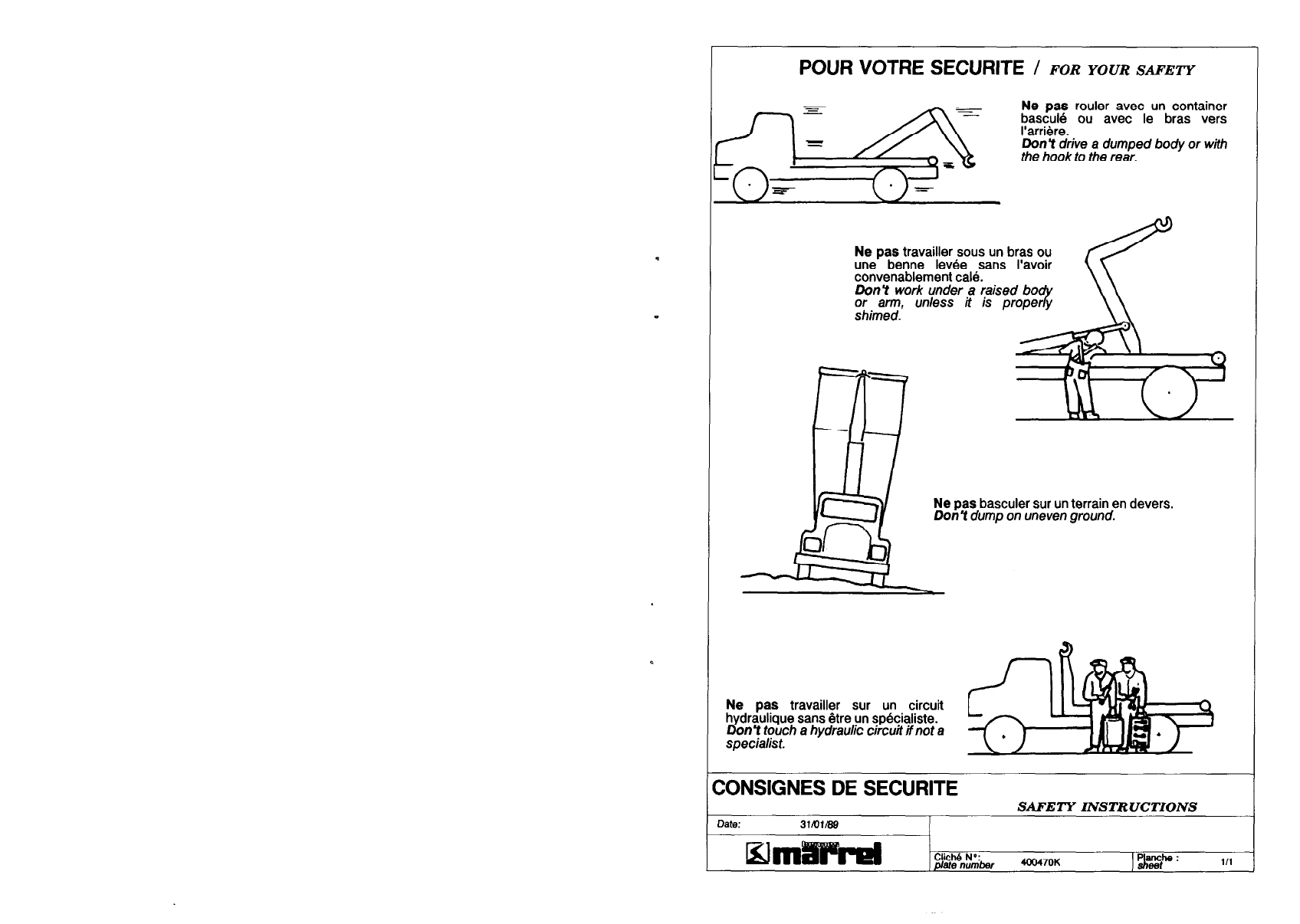
Ne pas rouler sans container avec le
bras en arrière.
TO DUMP A CONTAINER
1 - Jib is to be Mly extended during
dumping.
2 - Extend arm c linders to raise the
container and ump the load. The
J
safeiy hooks are self-engaged over
75 to 20 tippin angle. Never
retract the jib whr e dumping.Q
3 - Lower container after dumping.
4 - Desengage PTO.
;;;WNJLE A CONTAINER ON THE
1 - Retract thejib completely.
2 - Tiltthe arm to rhe rear. As soon
as tic container touches fhe
ground, release the brakes allowing
the bvck to move forward tiom the
container.
3 - Retum arm to forwardposition.
4 - Desengage PTO.
Never drive with the hook to the
rear.
CONSIGNES D’UTILISATION
Date: lomm
Klmii!lPH
OPERATING INSTRUCTIONS
CkM”$&4220621
pJgp:zc?
POUR VOTRE SECURITE / FOR YOUR SAFETY
Ne pas travailler sous un bras ou
une benne levée sans l’avoir
convenablement calé.
Do&t work under a (aised bo
;;i;ey., Mess ti is p
Ne pas basculer sur un terrain en devers.
DonY dumpon unevenground.
Ne pas travailler sur un circuit
hydraulique sans être un spkialiste.
Don Y touch ahydrauliccircuitifnot a
specialist.
ZONSIGNES DE SECURITE SAFETY INSTRUCTIONS
Date: 31lQi/89
Wrni!lFhzl CIicI- ND:
ate numLw 40047OK
pr Ill
ENTRETIEN
Date: lo/lom
5lmiiiiWel
MAINTENANCE
C ich6 N*:
atenumbw 4Z065M JL
Parme: ,@
Gralsser sous presslon toutes les
500 manoeuvres :
Voir les flèches sur le schéma :
- les articulationsdes vérins de bras
- l’articulationbras - biellette
- l’articulation arrière et les axes des
galets
- les cardans de la transmission de la
pompe, éventuellement.
Lubricate under pressure every 500
operations :
See the arroys on fhe,sketch :
- fhe atm c$nders art/culaeons .
- the armlD mg member artrculat!on
- fhe rear articulation and the roller
pins
- the joints on the pump drive line, if
arJY.
Graisser au plnceau toutes les 500 Lubricate with a brush every 500
manoeuvres : operations :
Voir les repères l sur le schéma : See the item l on the sketch :
- le crochet de levage - the lifting hook
- les axes des crochets de s&urité - the safetYhooks mechanism
- le dessus et le dessous de la potence - fhe top and bottom of the jib slide in
coulissant dans le bras fhe arm
Vérlfler les flxatlons du cadre au
châssis une fois par mois, plus souvent
les premières semaines d’utilisation.
Respecter les couples de serrage :
6m.kg (boulons de 14).
Check the subframe attachment to
the chassis. once a month, and more
otien during the first weeks of work.
Do not ovettiBhten the brackets : 6
m.kg = 44 ft./ s to 14 bol&.
Clrcult hydraullque :
vidange : voir instructions à la page
‘Huile”.
- vérifier et resserrer les raccords
fuyards, en particulier pendant les
premières semaines d’utilisation.
Cependant, ne
.P as exagérer le serrage
qui entraîneraa a rupturedes olives.
- essuyer périodiquement les tiges de
vérin avec un chiffon propre. En cas de
fuite importante, resserrer ou changer
le joint racleur de tige. Si la tige est
marqube, la fuite ne sera pas Bllminbe
sans changer la tige.
Hydraulic circuit :
oil change : see instructions on oil
data sheet.
- check af~d f%Jhfen fie leaking
fittings, speciaily afier the first weeks
of operation. However do not
overtight the fitting, it would break the
ferrules.
- clean fhe cylinder rods with a clean
rag and keep them slightly greasy. In
case of important leak on a rod,
tighten the seal in, or change it. If the
rod is dented, it doesnY help
changin 8 the seal, the rod must be
change .
ENTRETIEN
Date: 10/1we8
!Klm8!lUiPH
MAINTENANCE
42206!iM
1-z a2
SPECIFICATIONS SPECIFICATIONS
Huile pourtransmission h
type ISO.L.HV 32 (Index J draulique, Oil type /SO L.HV 32, for hydraulic
e viscosité = 150) circuits (viscosity index = 150).
Normes : Standards :
ISO 674314 ISO 674314
AFNOR NF E 46.603 AFNOR NF E 46.603
DIN 51.525 DIN 51.525
C’est une huile minérale possédant des pro- It must be a minera1oil for hydraulic
priétés extrême pression, anti-usure, grande circuits with anti-foam, anti-corrosion,
résistance a l’oxydation, pouvoir anti-corro- anti-wear propeties, and good
Sion, anti-mousse, desaeration et desémul- demulsibilitycharactenstics.
sion, bas pointd’écoulement.
Marque Température -20°C à + 60°C
ANTAR VISGA 32
BP BARTRAN HV 32
ELF HYDRELF 32
ESSO-EXXON UNIVIS N 32
FINA HYDRAN HW 32
GULF Q6 HANDEL 32
MOBIL DTE 13
SHELL TELLUS T 37
TOTAL EQUIVIS ZS 32
RENAULT ST37M
A moins d’une commande spéciale, nos
circuits sont faits en atelier avec une huile
ISO L.HV 32 pour cümats tempéres et
chauds.
En cas de temperature inferieure à - 2o”C,
prévoirune huile HV 22 ou plusfluide.
Unless otherwise specfied when
ordering, our systems are filled in
factory with ISO LHV 32 oil for
temperatelhotclimate.
In case the system is to be used with
temperature out of the above
brackets, contactyour oil supplier for
lower or higher grades.
VIDANGE
A effectuer toutes les 2OW manoeuvres,
ou une foisf!ar an, à I’entree de l’hiverpour
limiterles e ets de la condensation.
Procéder comme suit,dans l’ordre :
1 - Tous les verins étant rentrés et la pom-
pe arrêtée, vidan
toyer et le remplir 8 er le resetvoir, le net-
huile neuve.
MAINTENANCE
Changethe oil eve
or onceayear,just% 2000 operations
efore wrnter.
Proceed as follows :
1 - Ail cylinders retracted and pump
stopped, drainthe tankandfil1it up.
WILE
2 - Disconnect the fitting of the retum
line to the tankandconnect the retum
line to abin.
late: 2aa9/89
E;lmiliFPel Clich6 No:
plate numLmr
HYDRAULJC OIL
40024oL 01 pjgp: 1/2
3 - Sans laisser à aucun moment les com-
mandes ensemble au pointmort, embrayer
la prise, developper successivement tous
les vérins, puis arrêter immediatement la
prise de mouvement.
3 - Wittroufleavini allthe controls in
neuf@ run thepump, extend allthe
cylinders in sequence, and
immediatelystop thepump.
4 - Rebrancher la tuyauterie retour au re-
servoir. Embrayer la prise et faire rentrer et
sortir tous les V&ins, puis verifier et com-
pleter le niveau d’hurle, les vérins etant
tous rentrés.
4 - Again connect the retum line to
the tank.Run the
B ump, operating
ail cylinders in an out for bleeding,
and check the oil level a
ailcylinders areretracte8 ain when
.
- Ne amals lalsser tourner une pompe
Il
sans ulle. - Elever run a pump out of oil.
;6Erny maxl de nos pompes :
Nous tenons à votre disposition cette huile
ISO L.HV 32 en emballages de 5-25 et 200
litres.
;s;;tM,peed the pump over
. . .
We keep this oil availablein 5-25
and200 litre containers.
HUILE IfYlmAuLlc OIL4
PANNES / FAILURE
Fonctlonnement
hésitant
ORIGINE / ORIGIN REMEDES / REMEDIES
Mauvaise alimentation -Vérifier le niveau d’huile et
de la pompe compléter si nécessaire.
- Rechercher et éliminer une
prise d’air à la durite d’alimen-
tation.
PANNES / FAILURE ORIGINE / ORIGIN
Aucun mouvement
avec ou sans charge Commandes
par câble
REMEDES / REMEDIES
- Vérifier l’état des câbles
(rupture, cassure).
Prise de mouvement
- Par temps très froid :échauffer
I’huile, en maintenant la com-
mande sur la rentrée de potence
(quelques minutes).
- Verifier si la pompe tourne
(vibrationperceptible sur le
carter). Sinon, vérifier la com-
mande de la prise.
-Vérifier que le filtreou la crépine
ne soitpas colmaté, que la durite
ne soit pas écrasée.
Huile - Si la pompe tourne, vérifier qu’il
y ait de I’huile dans le réservoir.
IIpeut aussi y avoir défaut
d’amorçage.
-Vérifier le type et laviscosité
de I’huile.
Pompe
Hesitating
operation Bad oil supply
to the pump - Check the oillevel and top up
ifnecessary. Look for air intake.
- In cold weather : warm up by
operating thejib backward and
keep the control operated a
few minutes.
- Si la pompe a des organes
cassés, la réparer ou la change
Surtoutbien RINCER le circuit
hydraulique, toute I’huile doitêtr
filtrée et débarrassée des debri
de pompe.
No movement at a//,
even without any load Controls - Look for a broken control line.
- Check the strainer or filterand
the suction hose.
- Check the type of oil (grade,
viscosityindex). P.T.O. - tfpump does not rotate, check
the P.T.O. contd.
Fonctionnement
avec soubresauts
à la descente ou
descente trop rapide
Valve
d’équilibrage
- Vérifier l’état des pièces inté-
rieures (clapets, joints, siège,
ressort)de lavalve d’equilibrage.
Oil - If pump is tunning, checkthe oil
level.
Too fast or Check valve
Jerk-y operation ( dropping a loaded
container)
RECHERCHEDESPANNES
- Check or change the check valve.
Pump - lfpump is broken, change it
and RINSE the whole circuit
very caretilly.
RECHERCHE DE 5 PANNES
TROUBLE SHOOTING TROUBLE SHOOTING
Date: 17/11i89
EJrniTiWVel C ich6 N”:
ate number 422157N IsL3st 1iE
Panche :
Date: 17/11/89
CiddNY
#en& 422157N Iggp: 218
PANNES / FAILURE ORIGINE / ORIGIN REMEDES I REMEDIES PANNES I FAILURE
Le bras ne lève pas les
containers chargés, ou
s’arrête de lever à l’appui
de la blellette sur le cadre
Charge lourde - Surcharge, ou mauvaise
répartitionde la charge.
Réduire la charge à l’avant
du container.
- Relâcher les freins pendant
le levage.
Arm does not lift
a loaded container,
or stops lifting when
the rear tilting arm
cornes to rest on the
frame.
- Si le sol est boueux, mettre
des plaques sous les roues.
Limiteur -Vérifier le tarage du limiteur
général :350 bar maxi
(lire le manomètre quand
la potence vient en butée
ARRIERE).
L’essieu avant
quitte le sol -Vérifier la charge. Faire
vérifier l’empattement du
camion.
Débrayage interne
dans les vérins de
bras
- Le débrayage logé dans le
pistonpeut être fuyard.
Trouver sur quel verin
en isolantsuccessivement
chaque vérin. Nettoyer ou
changer le débrayage.
Huile impure - Après des années de travail
dur, ou en atmosphère très
poussièreuse, les tiroirsde
distributeurspeuvent être
usés et rayés. Réparer,
RINCER le circuitet changer
I’huile.
RECHERCHEDESPANNES RECHERCHEDE
TROUBLE SHOOTING
me: 17/11/89
5lmt/MVel C ich6 N”:
atenumber 422157N pathe: 3/8
Date: 17lll18Q
5lmtliiiFH
ORIGINE / ORIGIIV
Heavyload
Relief valve
Front axlelifts
off theground
By-pass valve
in am, cylinder
Oilpollution
PANNES
REMEDES I REMEDIES
- Overloador loaddistiibution :
removesome loadfrom the
front.
- Make sure to release the brakes
whilelifting.
-If the ground is too soft, layplate:
under the rear axle.
- Checkthe setting of the main
relief valve:
350 bar = 5 000 PSI max.
(readthe gaugewhen thejib
cornes to REAR stop).
- Checkthe weight. lf correct, see
your truckequipmentdealerfor
stretching the wheelbase.
- Changeleakingby-pass valve
inside thepiston. Find out which
cylinderhas afailingby-pass
valve,pluggingone of the 2 arm
cylinders.Cleanor changethe
checkvalve.
-Mer years of severe work,
earlier withpolluted oil : spool s
mightbe damaged,or cylinders
mightbe scratched, or piston
seals wom out : repair, RINSE
the circuit, andchangethe oil.
TROUBLE SHOOTING
C ich6 N?
ate numbar 422157N IP*: 4/8