Meva STB Series Owner's manual
Technical Instruction Manual
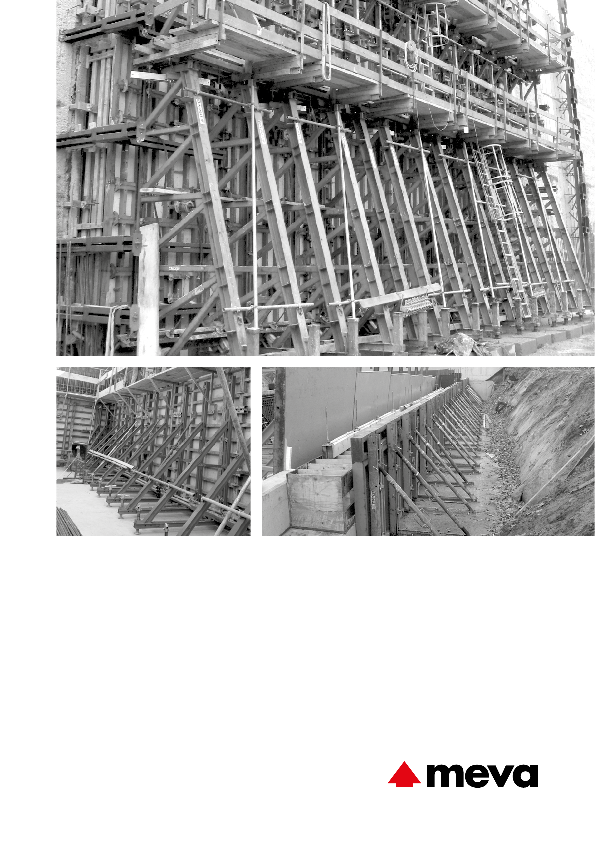
Support Frame STB

The support frame is mainly used for pouring against existing struc-
tures (walls, rock, soil, sheet piling, foundations, etc.) if only one side
of the formwork can be erected. For practical reasons it is generally
not possible to tie through the formwork. Hence, the total fresh-con-
crete pressure has to be transferred via the formwork into the support
frame and then on into the foundation. The MEVA support frame
consists of a welded and painted steel construction.
See the separate STB load charts for details about the loads that occur
in standard applications.
Permissible anchor loads according to DIN 18216
Anchor system Permissible loading
DW 15 90 kN per tie rod
DW 20 160 kN per tie rod
DW 26.5 250 kN per tie rod
When using the support frames, special attention must be paid to the
following:
ÆThe foundations and floor slabs, etc. must be able to withstand
the tensile and compressive forces that occur. A structural verification
may be required.
ÆThe "opposite side" of the single-sided formwork, i.e. the exist-
ing structure, must also be able to resist the fresh-concrete pressure.
ÆThe DW tie rods must not be welded, heated or deformed.
ÆFor more complex or special cases not dealt with in this manual
please contact the MEVA experts for advice.
ÆDeviations from the versions described in this manual always
require a separate structural verification.
Attention
Check on-site to make sure that the tensile forces Z and the compres-
sive forces V that occur can be safely transferred into the foundation
or floor slab. In particular, the concrete strength and the degree of
reinforcement used need to be reviewed. If the support frames are
used on top of slabs – for example in underground garages – support
the slab where the vertical forces V occur in order to transfer these
into the foundation.
Abbreviations, measurements, figures and tables, etc.
The abbreviation STB is used for the support frame. DIN means
Deutsche Industrie-Norm (German Industrial Standard). E DIN (E =
Entwurf / draft) means that the DIN is in draft status and not yet
approved. Any further abbreviations are explained where they are
used for the first time.
TÜV means Technischer Überwachungsverein. This is the independ-
ent German organisation that tests the safety of technical installa-
tions, machinery and motor vehicles. If a product passes the test, it
is permitted to carry the GS seal. GS stands for Geprüfte Sicherheit
(approved safety).
Measurements: This manual uses the metric system, i.e. m (for metre),
cm (for centimetre) and mm (for millimetre).
Non-defined dimensions are in cm.
The page numbers in this manual start with STB. The figures and
tables are numbered per page. Depending on its product abbrevia-
tion, a cross reference in the text refers to a page, table or figure in
this or in another manual. This is indicated by the product code with
which the cross-reference begins.
Product features
STB-2 Technical Instruction Manual / Status November 2019
STBSupport frame
Contents
This Technical Instruction Manual contains information, instructions
and tips that describe how to use the MEVA equipment on the
construction site in a proper, quick and economic way. Most exam-
ples shown are standard applications that will occur in practice most
often. For more complicated or special applications not covered in this
manual, please contact the MEVA experts for advice. They will help
you without delay.
When using our products, the federal, state and local occupational
health and safety regulations must be observed. Please observe the
assembly instructions that your local contractor or employer has cre-
ated for the site on which the MEVA equipment is used. Such instruc-
tions are intended to minimise site-specific risks and must contain the
following details:
ÆThe order in which all working steps including assembly, conver-
sion and disassembly must be carried out
ÆThe weight of the panels and other system parts
ÆThe type and number of ties and braces as well as the distance
between them
ÆThe location, number and dimensions of working scaffolds
including the working area and fall protection equipment required
ÆAttachment points for panel transport by crane. With regard to
panel transport, please observe this manual. Any deviation will require
structural verification.
Important: Generally, only well-maintained material may be used.
Damaged parts must be replaced. Use only original MEVA spare parts
for replacement.
Attention: Never wax or oil assembly locks!
Please note
Product overview.............................................................................. 4
Support frame STB 300/300 plus ...................................................... 6
Support frame STB 300 plus.............................................................. 7
Support frame STB 450................................................................... 11
Pre-assembly of support frame units ............................................... 12
Diagonal bracing ............................................................................ 13
Workplaces..................................................................................... 14
Workplaces – SecuritBasic............................................................... 15
Workplaces – Walkway bracket ...................................................... 16
Access ladder.................................................................................. 17
Anchoring details – General............................................................ 18
Anchoring – versions ...................................................................... 22
Anchoring details for STB 300......................................................... 23
Anchoring details for STB 300 plus ................................................. 24
Anchoring details for STB 450......................................................... 25
Anchoring – Installing anchor holders DW 15 – DW 26.5................ 26
Anchoring – Installing single/double anchors .................................. 28
Anchoring – installation of the anchor extension ............................ 30
Anchoring – Upstand bracket ......................................................... 31
Stop ends ....................................................................................... 32
Inside corner with cross brace STB and STB 300/300 plus ............... 34
Inside corner with cross brace STB and STB 450.............................. 37
Crane ganging................................................................................ 40
Moving STB units on a trolley.......................................................... 41
STB special connector ..................................................................... 43
Brace bracket SK 150...................................................................... 44
Brace bracket 80............................................................................. 46
Transport: stacking material............................................................ 47
Transport: loading trucks ................................................................ 48
Services .......................................................................................... 49
Poduct list....................................................................................... 51
Load charts..................................................................................... 85
STB-3Technical Instruction Manual / Status November 2019
STBSupport frame
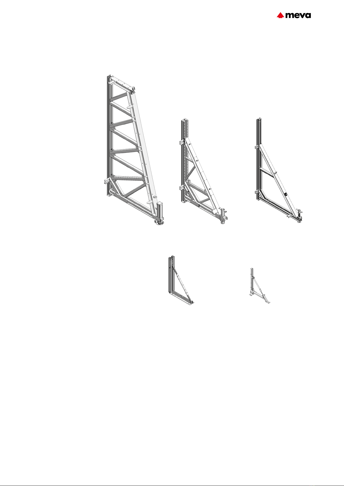
Product overview
Fig. 4.1 Support frame STB 450 Fig. 4.2 Support frame STB 300 plus
Fig. 4.4 Brace bracket SK 150 Fig. 4.5 Brace bracket 80
Fig. 4.3 Support frame STB 300
Walls up to a pouring height of
13.50m can be formed from one
side using three support frame
versions.
ÆSTB450 up to a height
of 5.20m, with height exten-
sions150 and, if required, addi-
tional accessories up to 13.50m
(Fig.4.1 and page STB-11).
ÆSTB300 plus up to a height
of 3.25m, with height exten-
sions up to a height of 4.50m
(Fig.4.2 and page STB-7.
ÆSTB300 up to a height of
3.30m (Fig.4.3 and page STB-
21.
Two support frame sizes enable
stop ends for floor slabs and
slab edges up to 1.50m to be
formed.
ÆBrace bracket150 up to a
height of 1.50m
(Fig.4.4 and page STB-44.
ÆBrace bracket80 up to a
height of 0.8m
(Fig.4.5 and page STB-46.
STB-4 Technical Instruction Manual / Status November 2019
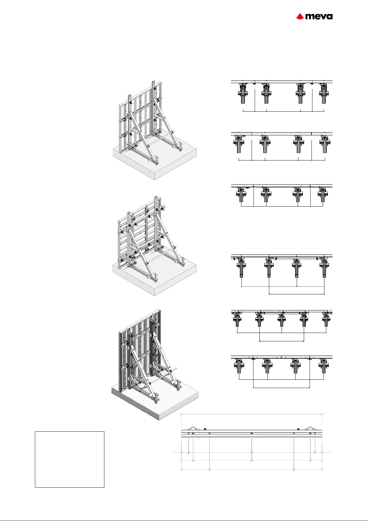
STBSupport frame

The STBsupport frames and the
brace brackets can be combined
with all MEVA wall formwork
systems as well as with special
designs.
From a structural and economic
point of view and depending
on the formwork system used,
it may be more advantageous
to use the support frame with
vertical (Fig.5.1) or horizontal
panels (Fig.5.2).
The support frame can be
attached to the MEVA wall form-
work panel from the frame side
with flange screw18 (Fig.5.3).
Alternatively, it can be attached
from the facing side using fixing
screw35 and articulated flange
nut15/120 or flange nut100
(Figures5.4 and 5.5).
Attention
ÆWhen using the STB unit
vertically, the spindle must be
set to the middle position before
mounting the STB on the form-
work. This ensures that it can
be perfectly adapted to suit the
supporting surface.
ÆRefer to the product list for
the spindle stroke.
ÆBefore pouring, ensure that
all STB spindles and additional
braces are secure and contact
the ground.
Product overview
Fig. 5.1 Support frame STB 300 with vertical panels Fig. 5.2 Support frame STB 450 with horizontal panels
Fig. 5.4 Detail – Fixing screw on the support frame side Fig. 5.5 Detail – Fixing screw on the facing side
Fig. 5.3 Detail – Flange screw 18, attachment on the support frame side
Spindle
STB-5Technical Instruction Manual / Status November 2019
STBSupport frame
Support frame STB 300/300 plus
Fig. 6.5 Support frame STB 300 with vertical panels
Fig. 6.1 Support frame STB 300 with horizontal panels
Fig. 6.2 StarTec horizontal, with fixing screw
Fig. 6.3 Mammut 350 horizontal, with fixing screw
Fig. 6.6 StarTec vertical, with flange screw
Fig. 6.7 Mammut vertical, with flange screw
Description Ref. No.
Support frame STB 300 ......... 29-402-62
Flange screw 18 .................... 29-401-10
Flange screw 28 .................... 29-401-12
Fixing screw
35/DW 15 ............................. 29-401-20
Articulated flange nut
15/120.................................. 29-900-10
Flange nut 100 ..................... 29-900-20
Crossbeam 300 ..................... 29-403-05
Pouring height
The STB300 (Figures6.1 and
6.5) is used up to a pouring
height of 3.30m.
The STB300plus (Fig.6.9) is
used up to a pouring height of
3.25m and can be equipped
with height extensions for a
pouring height up to 4.50m.
Horizontal panels
The support frame is attached to
the multi-function profiles using
flange screws18. Alternatively,
it can be attached through the
tie holes of the formwork using
fixing screws35 and flange
nuts100 or articulated flange
nuts15/120 (Figures6.1 to 6.4).
Vertical panels
When using vertical StarTec
and Mammut/Mammut350
formwork (Figures6.5 to 6.7),
the crossbeam300 is used
(Fig.6.10). When used hori-
zontally between the formwork
panel and the support frame, the
crossbeam300 allows units to be
assembled.
The support frame is attached
to the multi-function profile of
the formwork panel using tie
rodsDW and flange nuts100 or
articulated flange nuts15/120
(Fig.6.5).
When MammutXT is used verti-
cally, an additional crossbeam is
not required (Fig.6.8).
Fig. 6.4 Mammut XT horizontal, with fixing screw
Fig. 6.8 Mammut XT vertical, with flange screw
Fig. 6.10 Crossbeam 300
ST 270 ST 270
ST 270
55 5555 55
160
M 350 M 350
M 350
55 55
55 55
140
Mammut XT Mammut XT
Mammut XT
55 55
55 55
140
ST 135
ST 135
135
ST 135
135 135
Formwork unit
ST 135 ST 135
M 350
125
Formwork unit
M 350 M 350 M 350
125 125 125
Mammut XT
62.5 125
Formwork unit
62.5 62.5 62.5
Mammut XT Mammut XT Mammut XT
15
25 25
15
60 60
180
125 125
300
Fig. 6.9 Support frame STB 300
plus with horizontal panels
STB-6 Technical Instruction Manual / Status November 2019
STBSupport frame
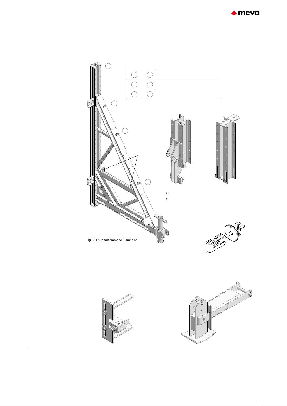
Support frame STB 300 plus
The STB300 plus (Fig.7.1) is
used up to a pouring height of
3.25m.
With a maximum of three
STBheight extensions50
(Fig.7.2), the STB300plus can
be used up to a pouring height
of 4.50m (see page STB-9).
The STBcompensation rail
(Fig.7.3) enables the support
frame unit to be dowelled to the
slab. It is attached to the support
frame or to the STBheight exten-
sion with the STBfixing screw
(Fig.7.4) (see page STB-10).
The STBpanel support (Fig.7.5)
ensures that the STB formwork
panel unit does not shift unin-
tentionally when being reposi-
tioned. Furthermore, additional
accessories such as a walkway
bracket can be attached to the
integrated multi-function nut
(see page STB-8).
When height-extending the
support frame using STBheight
extensions, additional braces are
attached to the STBbase exten-
sion57 (Fig.7.6).
The support frame300plus
enables additional scaffold tubes
to be installed at the positions
provided in order to provide
rigidity (Fig.7.1).
Fig. 7.1 Support frame STB 300 plus
Fig. 7.2
STB height extension 50
Fig. 7.3
STB compensation rail
Fig. 7.5 STB panel support Fig. 7.6 STB base extension 57
Description Ref. No.
Support frame STB 300 plus . . 29-402-60
STB height extension 50 ........ 29-402-63
STB compensation rail ........... 29-402-66
STB panel support ................. 29-402-68
STB base extension 57 .......... 29-402-69
STB fixing screw .................... 29-401-19
Fig. 7.4 STB fixing screw
1
4
2
3
Crane attachment points
and Support frame with formwork
and Support frame installed vertically
and Support frame installed horizontally
21
1 3
41
Positions for the
attachment of addi-
tional scaffold tubes to
provide rigidity
STB-7Technical Instruction Manual / Status November 2019
STBSupport frame

Support frame STB 300 plus
The STBpanel support (Fig.8.2)
prevents the STB formwork panel
unit shifting unintentionally
when being repositioned. Fur-
thermore, additional accessories
such as a walkway bracket can
be attached to the integrated
multi-function nut (Figures8.1,
8.3 and 8.4).
The panel support is attached to
the support frame300plus using
the integrated screws. The posi-
tion must be selected so that it is
located on the formwork panel
between two crossbeams or on
a cross stiffener (Figures8.3 and
8.4).
Fig. 8.1
Fig. 8.3
STB panel support
Walkway bracket
Description Ref. No.
Support frame STB 300 plus . . 29-402-60
STB panel support ................. 29-402-68
Fig. 8.2 STB panel support
Multi-function nut
Fig. 8.4
STB panel support
STB-8 Technical Instruction Manual / Status November 2019
STBSupport frame

Support frame STB 300 plus
Configuration Pouring height (m)
STB 300 plus 2.50 to 3.25
STB 300 plus + 1 height extension Up to 3.50
STB 300 plus + 1 height extension + 1 brace + 1 STB base extension 57 Up to 3.75
STB 300 plus + 2 height extensions + 2 braces + 2 STB base extensions 57 Up to 4.25
STB 300 plus + 3 height extensions + 3 braces + 3 STB base extensions 57 Up to 4.50
With a maximum of three
STBheight extensions50
(Fig.9.2), the STB300plus can
be used up to a pouring height
of 4.50m.
The STBheight extension50 is
attached to the support frame
or the STBheight extension50
located below using the inte-
grated screws (Fig.9.2).
The braces can be attached to
the STBheight extension50 and
to the STBbase extension57
(Figures9.1 and 9.2).
Refer to Table9.4. for the con-
figuration of the support frame
unit as a function of the pouring
height.
Refer to the STB load charts for
information on the forces that
occur and the type of bracing.
Table 9.4
Description Ref. No.
Support frame STB 300 plus . . 29-402-60
STB height extension 50 ........ 29-402-63
STB base extension 57 .......... 29-402-69
Zeichnung Nr. 3000_0107
Stand: 17.10.2018/bhe
Fig. 9.1
STB height extension 50
STB base extension 57
Support frame STB 300 plus
Bracing
Positions for the attachment of addi-
tional scaffold tubes to provide rigidity
Fig. 9.2 STB height extension 50 Fig. 9.3 STB base extension 57
Attachment point for
bracing
Attachment point for
bracing
STB-9Technical Instruction Manual / Status November 2019
STBSupport frame

Fig. 10.1
STB compensation rail (dowelled to the slab)
Timber
STB height extension 50
STB base extension 57
Support frame STB 300 plus
Bracing
Positions for the attachment of addi-
tional scaffold tubes to provide rigidity
Fig. 10.4 Detail view of STB fixing screw
Fig. 10.5 Detail view of STB fixing screw
STB fixing screw
Detail views in Fig-
ures10.4 and 10.5
Support frame STB 300 plus
The STBcompensation rail
(Fig.10.1) enables the support
frame unit to be dowelled to the
slab. A job-built square timber
bridges the gap to the formwork
panel.
The compensation rail is attached
to the support frame or the
STBheight extension using the
STBfixing screw (Figures10.2
and 10.3).
Description Ref. No.
Support frame STB 300 plus . . 29-402-60
STB compensation rail ........... 29-402-66
STB base extension 57 .......... 29-402-69
STB fixing screw .................... 29-401-19
Fig. 10.2 STB compensation rail
Fig. 10.3 STB fixing screw
STB-10 Technical Instruction Manual / Status November 2019
STBSupport frame
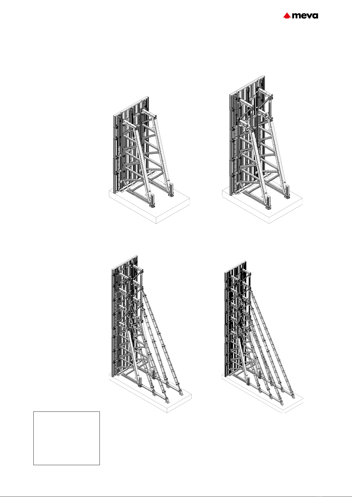
Support frame STB 450
Possible applications
The STB 450 is designed for
single-sided formwork up to
5.20m (Fig. 11.1). Using height
extensions 150 and other acces-
sories as required, the STB450
allows single-sided formwork to
be erected with the following
heights:
ÆUp to 6.70m – One height
extension (Fig. 11.2)
ÆUp to 8.20m – Two height
extensions, base extension,
Triplex SB braces
ÆUp to 9.40m – Three height
extensions, base extension,
Triplex SB braces (Fig.11.3)
ÆUp to 11.00 m – Four
height extensions, base exten-
sion, Triplex SB braces (Fig.11.4)
ÆUp to 12.50 m – Five height
extensions, base extension,
Triplex SB braces
ÆDepending on the
construction site and using a
corresponding number of height
extensions and Triplex SB braces,
support frame constructions for
formwork heights up to 13.50m
can also be built.
Attention
ÆBefore pouring, ensure that
all STB spindles and additional
braces are secure and contact
the ground.
Fig. 11.2 Up to a formwork height of 6.70m:
Four fixing screws are required for each STB
Fig. 11.1 Up to a formwork height of 5.20m:
Three fixing screws are required for each STB
Fig. 11.4 Up to a formwork height of 11.00m:
Seven fixing screws are required for each STB
Fig. 11.3 Up to a formwork height of 9.40m:
Six fixing screws are required for each STB
Description Ref. No.
Support frame STB 450 ......... 29-406-00
Height extension 150 ............ 29-406-10
Base extension ...................... 29-406-20
Fixing screw
35/DW 15 ............................. 29-401-20
Articulated flange nut
15/120.................................. 29-900-10
Flange nut 100 ..................... 29-900-20
Flange screw 18 .................... 29-401-10
STB-11Technical Instruction Manual / Status November 2019
STBSupport frame

Pre-assembly of support frame units
The surface on which the form-
work and the support frames are
pre-assembled should be clean,
even and capable of supporting
the total weight. The support
frames are attached to the rear
of the horizontal formwork
panels (Fig.12.1).
Assembly
ÆThe support frame is
attached to the formwork’s mul-
ti-function profiles using flange
screw18. Alternatively, it can
be attached using the tie holes
of the formwork with fixing
screws35 and articulated flange
nuts15/120 or flange nuts100.
The fixing screws must be in-
serted through the tie holes and
secured to prevent them falling
out, using the flange nut100 for
example, before the formwork
panel is placed on the ground.
ÆThe height extensions are
bolted to the support frame or
height extension below using
the eight (8) M20x50 screws and
M20 nuts supplied.
ÆThe pre-assembled units
should rest on square timbers
(face down) on the ground be-
fore they are flown into place.
Assembly of the Triplex SB
braces
Depending on the overall height,
it may be necessary to attach
TriplexSB braces to the height
extensions150 and the base
extensions. The fastening ele-
ments required are supplied with
the height and base extensions
(Figures 12.2 to 12.4).
Fig. 12.2
Fig. 12.1
Fig. 12.3 – Detail view of the upper
Triplex connection
Fig. 12.4 – Detail view of the lower
Triplex connection
Spindle
Attention
ÆWhen using the STB unit
vertically, the spindle must be
set to the middle position before
mounting the STB on the form-
work. This ensures that it can
be perfectly adapted to suit the
supporting surface.
ÆBefore pouring, ensure that
all STB spindles and additional
braces are secure and contact
the ground.
ÆRefer to the Triplex Tech-
nical Instruction Manual (www.
meva.net).
STB-12 Technical Instruction Manual / Status November 2019
STBSupport frame

Diagonal bracing
Scaffold tubes with Ø
48.3 x 4.05mm, bolt-on couplers
48/M14 and swivel-joint couplers
48/48 are needed to build the
diagonal bracing required.
A horizontal tube is required
for STB300 (Fig.13.1) and
STB300plus (Fig.13.2).
The STB 450 requires two hori-
zontal and one diagonal scaffold
tube (Fig. 13.3).
If height extensions are used,
additional horizontal scaffold
tubes must be installed from the
second height extension upwards
(Figures13.4 and 13.5).
Fig. 13.3 Fig. 13.4
Fig. 13.1
Fig. 13.2
Description Ref. No.
Scaffold tube 48/200 ............ 29-412-23
Scaffold tube 48/300 ............ 29-412-26
Scaffold tube 48/400 ............ 29-412-27
Swivel-joint coupler
48/48.................................... 29-412-52
Bolt-on coupler
48/M14 ................................ 40-080-70
Fig. 13.5
STB-13Technical Instruction Manual / Status November 2019
STBSupport frame
Workplaces
Above a height 2.00m the risk
of falling must be assessed.
SecuritBasic
The support frame STB450 can
be equipped with the safety
system SecuritBasic (Fig.14.1)
for safe and ecient work at
all heights. This prevents falling
accidents and at the same time
increases work eciency.
Conventional
If a scaffold is erected con-
ventionally (Fig.14.2) or with
walkway brackets (see page
STB-16), DINEN12811-1 and
DIN4420-1 must be observed.
Minimum cross section of
handrail and midrail: for a post
spacing up to 2.00m: 15x3cm
For a post spacing of up to
3.00m: 20 x 4cm.
We recommend the use of safety
meshes. They are quick and safe
method to provide fall protec-
tion.
Attention
ÆWhen using our products,
the federal, state and local
codes and regulations must be
observed.
Fig. 14.1
Fig. 14.2
STB-14 Technical Instruction Manual / Status November 2019
STBSupport frame

Workplaces – SecuritBasic
The support frame450 as well as
the height extension150 can be
equipped with the SecuritBasic
platform2470 with integrated
access ladder (Fig.15.1) on the
2.50m wide Mammut panel.
Refer to Tables15.2 to 15.4.
for the type and quantity of the
parts required for the complete
unit as depicted in Fig.15.1 or
for individual platforms.
Bill of material (complete unit as in Fig.15.1)
Posi-
tion
Quan-
tity
Ref. no. Description
1 2 29-406-00 Support frame STB 450
2 8 29-406-10 STB height extension 450
3 2 29-406-25 Horizontal girder STB
450 SB
4 1 29-406-66 Toe board STB 1290 SB
5 2 29-406-64 Toe board STB 480 SB
6 8 29-106-80 Guardrailing post 48/120
UK
7 19 29-412-50 Rigid coupler 48x48
8 8 29-601-78 Side railing hinged SB
tube coupler
9 6 29-406-27 Horizontal girder ST ex-
tension 150 SB
10 3 29-406-68 Toe board STB 2470 SB
11 2 29-406-62 Toe board holder STB SB
12 2 29-601-92 Support for guardrailing
post IC SB
13 2 29-406-29 Front railing post retract-
able STB 450
14 4 29-603-45 Telescopic ladder 1700-
3180 SB
15 8 29-406-87 STB special connector
16 4 29-600-15 Alu platform M 2470 SB
with hatch
17 10 29-603-55 Scaffold tube 48.3/2470
SB
18 1 29-603-80 Ladder fixture panel SB
Table 15.2
Fig. 15.1
1
5
6
7
9
10
6
4
2
5
11
12
13
14
15
3
2
1
6
7
7
9
9
9
10
10
16
16
16
16
17
8
8
8
8
18
Bill of material (individual platform on STB 450)
Posi-
tion
Quan-
tity
Ref. no. Description
3 2 29-406-25 Horizontal girder STB
450 SB
4 1 29-406-66 Toe board STB 1290 SB
5 2 29-406-64 Toe board STB 480 SB
6 2 29-106-80 Guardrailing post 48/120
UK
7 5 29-412-50 Rigid coupler 48x48
8 2 29-601-78 Side railing hinged SB
tube coupler
11 2 29-406-62 Toe board holder STB SB
14 1 29-603-45 Telescopic ladder 1700-
3180 SB
16 1 29-600-15 Alu platform M 2470 SB
with hatch
17 2 29-603-55 Scaffold tube 48.3/2470
SB
18 1 29-603-80 Ladder fixture panel SB
Bill of material
(individual platform on height extension 150)
Posi-
tion
Quan-
tity
Ref. no. Description
3 2 29-406-27 Horizontal girder ST ex-
tension 150 SB
6 2 29-106-80 Guardrailing post 48/120
UK
7 5 29-412-50 Rigid coupler 48x48
8 2 29-601-78 Side railing hinged SB
tube coupler
10 1 29-406-68 Toe board STB 2470 SB
14 1 29-603-45 Telescopic ladder 1700-
3180 SB
15 2 29-406-87 STB special connector
(also refer to the STB load
charts)
16 1 29-600-15 Alu platform M 2470 SB
with hatch
17 2 29-603-55 Scaffold tube 48.3/2470
SB
Additional parts on the uppermost height extension
12 2 29-601-92 Support for guardrailing
post IC SB
13 2 29-406-29 Front railing post retract-
able STB 450
17 2 29-603-55 Scaffold tube 48.3/2470
SB
Table 15.3
Table 15.4
STB-15Technical Instruction Manual / Status November 2019
STBSupport frame
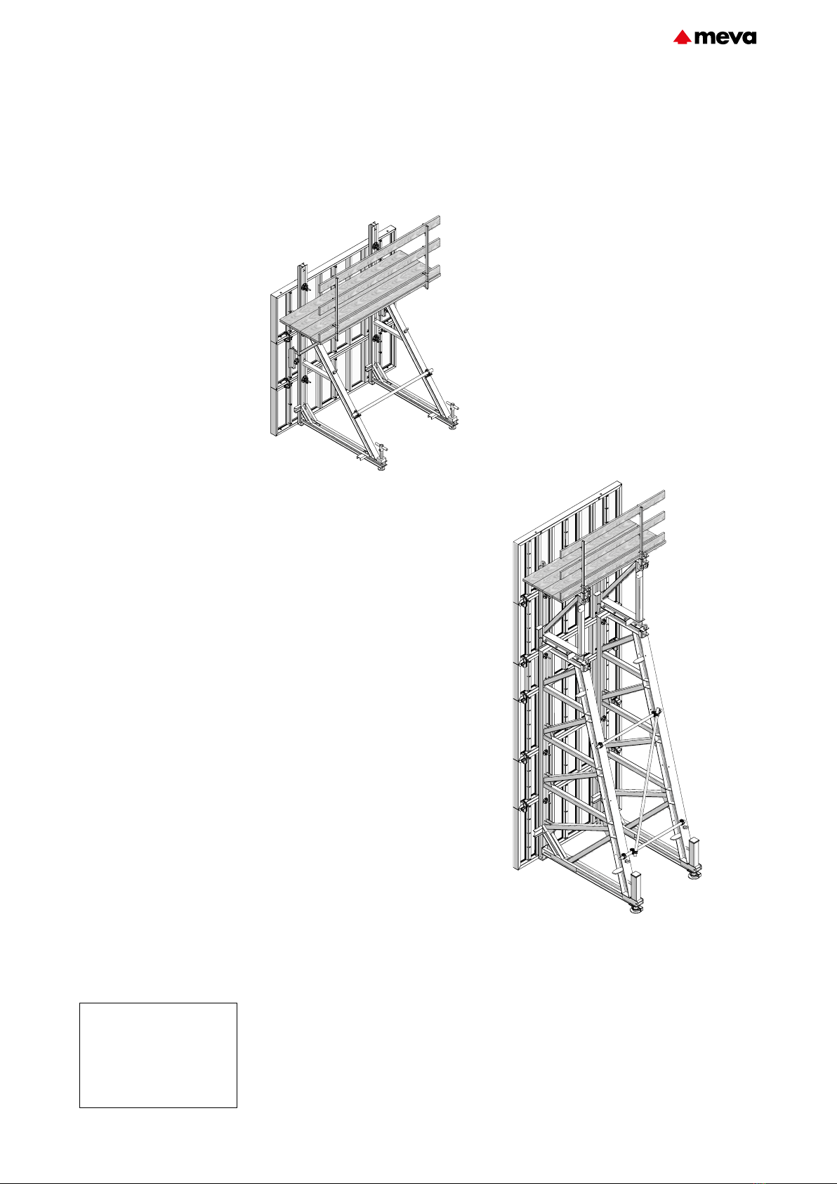
Workplaces – Walkway bracket
Fig. 16.1 STB 300 with walkway bracket 90
Fig. 16.2 STB 450 with conventional scaffold on STB height extension
Attachment of boards to the walkway
bracket with screws (∅ 10mm and a mini-
mum length of 110mm)
Attachment of boards to the STB or height extensions with
screws (e.g. M20x75). The guardrailing posts are easily and
safely inserted into the guardrailing post supports of the
support frame or height extension.
Description Ref. No.
Walkway bracket 90 ............. 29-106-00
Guardrailing post 100 ........... 29-106-75
Guardrailing post 140 ........... 29-106-85
Guardrailing post 48/120 ...... 29-106-80
Side railing 90/100 ................ 29-108-20
Side railing 125/100 .............. 29-108-30
Hexagon-head bolt M20x75 . 63-119-91
Working platforms are built using
walkway brackets 90 (Fig.16.1)
together with guardrailing posts.
The procedure is as for two-sided
wall formwork. For details see
the Technical Instruction Manual
of the formwork you are using.
For safe access to the platform
we recommend using the MEVA
Stair Tower.
Permissible load:
1.5 kN/m², load class2 according
to DIN12811-1. Maximum influ-
ence width: walkway bracket90
= 1.80m
Planking classification S10.
Platform layout
The STB units can be set up flex-
ibly and combined with different
formwork systems and heights.
When planning, take the plat-
form layout and the fall height
into account.
STB 450
The planks and boards can be
attached to the support frame
or the height extension (Fig-
ures16.3 and 16.4). The guard-
railing posts are inserted directly
into the support for guardrailing
post of the STB 450 or the height
extension.
STB-16 Technical Instruction Manual / Status November 2019
STBSupport frame
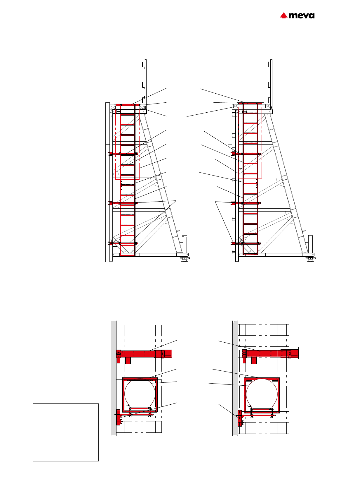
Fig. 17.1 STB 450 with ladder access; STB
attached directly to the formwork.
Fig. 17.2 STB 450 with ladder access; crossbeam or
alignment rail between STB and formwork.
Fig. 17.3 Ladder access with access hatch
without crossbeam
Fig. 17.4 Ladder access with access hatch and
crossbeam
Access hatch
Planking t = 50 mm
Timber
Ladder fixture 33/45
Ladder 243
Safety cage 210
Ladder connector
Extension ladder 210
An access ladder with safety
cage is required if the support
frame 450 is used. The distance
from the ground to the safety
cage must not exceed 3m. The
ladders are attached to the wall
formwork panels using the lad-
der fixture 33/45, regardless of
whether a crossbeam or align-
ment rails are used (Figures17.1
to 17.4). The ladder fixture is
bolted to the multi-function pro-
files of the wall formwork panels
using flange screws 18.
Three ladder fixtures 33/45 are
required for formwork heights
between 350cm and 450cm.
For heights above 450cm please
contact MEVA.
Note
ÆAlternatively, a MEVA Stair
Tower can be employed to
access the working level.
ÆA MEVA Stair Tower is re-
quired above a height of 5.00m
if there are no intermediate
working levels.
Description Ref. No.
Ladder fixture 33/45 ............. 29-404-35
Ladder 243 ........................... 29-416-50
Extension ladder 210 ............ 29-414-60
Extension ladder 90 .............. 29-416-60
Extension ladder 60 .............. 29-416-62
Safety cage 210 .................... 29-414-85
Safety cage 85 ...................... 29-414-90
Safety cage 40 ...................... 29-416-90
Ladder connector .................. 29-414-70
Access hatch KLK .................. 29-416-05
Access hatch
Safety cage
Ladder fixture 33/45
Support frame 450
Access ladder
Ladder fixture 33/45
STB-17Technical Instruction Manual / Status November 2019
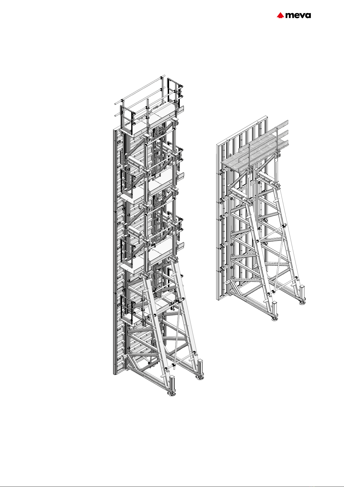
STBSupport frame
Anchoring details – General
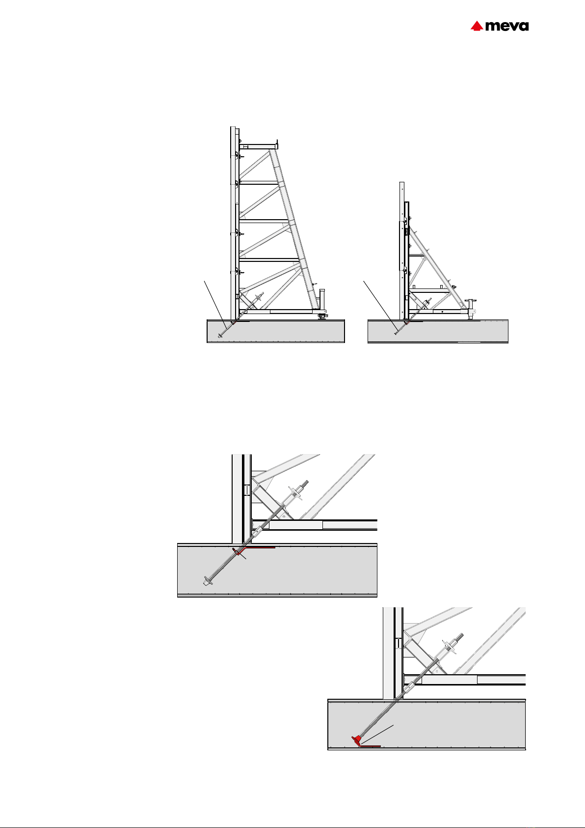
Fig. 18.1 Support frame STB 450
Anchoring
Anchors for support
frame450 (Fig.18.1), support
frame300plus (Fig.18.2) and
support frame300 can be made
for different floor slab thick-
nesses using anchor loops or
DW tie rods, coupling nuts and
anchoring auxiliaries.
All parts are designed for the use
of DW15, DW20 and DW26.5
tie rods.
The anchoring auxiliaries can
be attached either to the upper
(Fig.18.3) or to the lower rebar
layer (Fig.18.4) depending on
the slab thickness or the number
and density of rebars. The angle
of installation of the tie rods is
automatically correct due to the
shape of the anchoring auxilia-
ries (45°).
Depending on the version it may
be possible to recover and reuse
the tie rods (see page STB-21).
Fig. 18.3
Fig. 18.4
Anchoring
Fig. 18.2 Support frame STB 300 plus
Anchoring auxiliary on the upper
rebar layer
Anchoring auxiliary on the lower
rebar layer
STB-18 Technical Instruction Manual / Status November 2019
STBSupport frame

Anchoring details – General
Decisive for the choice of tie
rod are the forces that occur at
the anchor point of the support
frame. Anchoring can be per-
formed as follows:
ÆWith tie rod DW15
(Fig.19.1) and M cross stiffener
44.
ÆWith tie rod DW20 or
DW26.5 and twin channel 80/22
or 245/22 (Fig. 19.5).
ÆWith anchor loop15
(Fig.19.2) or 20 and twin
channel (Figures19.3 and 19.4)
or with anchor loop 15 or 20
turned through 180° (Fig.19.4).
Contact the structural engineer if
additional rebars are required.
Maximum anchoring loads:
Tie rod DW
DW 15 = 90 kN per tie rod
DW 20 = 160 kN per tie rod
DW 26.5 = 250 kN per tie rod
Anchor loop
DW 15 = 180 kN
DW 20 = 320 kN
Fig. 19.3 Fig. 19.4
Fig. 19.5
Fig. 19.2 Anchor loop
Description Ref. No.
Tie rod DW 15/90 ................. 29-900-80
Tie rod DW 20/120 ............... 29-900-97
Tie rod DW 26.5/80 .............. 29-900-75
Anchor loop 15 ..................... 29-001-20
Anchor loop 20 ..................... 29-001-25
M cross stiffener 44 .............. 29-401-02
Twin channel 245/22............. 29-406-30
Twin channel 80/22............... 29-406-35
Twin channel 80/12............... 29-406-38
Fig. 19.1 Tie rod DW
Anchor loop
Twin channel 80/12
Anchor loop, rotated
through 180°
Twin channel 80/12
Tie rod DW
Twin channel 80/22 or 245/22
STB-19Technical Instruction Manual / Status November 2019
STBSupport frame

Anchoring details – General
Fig. 20.1 Anchor holder DW 15 – DW 26.5
Fig. 20.2 Single anchor DW
Description Ref. No.
Anchor holder
DW 15 – DW 26,5 ................ 29-925-80
Single anchor DW 15 ............ 29-925-40
Single anchor DW 20 ............ 29-925-45
Single anchor DW 26.5 ......... 29-925-50
Double anchor DW 15 .......... 29-925-60
Double anchor DW 20 .......... 29-925-65
Planing cap ........................... 29-917-75
Planing cap DW 26.5 ............ 29-917-85
Coupling nut 15 ................... 29-900-55
Coupling nut 20 ................... 29-900-50
Coupling nut 26.5 ................ 29-900-56
Fixed anchor DW 15 ............. 29-926-60
Fixed anchor DW 20 ............. 29-926-65
Fixed anchor DW 26.5 .......... 29-926-70
Fig. 20.4 Planing cap
Anchoring auxiliaries –
Individual parts
ÆAnchor holder
DW15–DW26.5 (Fig.20.1),
attachment to the upper rebar
layer. The use of the anchor
holderDW is recommended for
slab thicknesses greater than
approx.40 cm or for slabs with
a large number and density of
rebars.
It is bent to 45° and can be
used with DW 15, DW 20 and
DW 26.5 tie rods. If the anchor
holder DW with anchor sleeve is
used, it can be used with tie rods
DW15.
ÆSingle/double anchor DW,
attachment to the lower rebar
layer.
For slab thicknesses up to
approx. 40cm we recommend
the use of single anchors
(Fig.20.2) or double anchors
(Fig.20.3).
Maximum loading:
Single anchor DW
DW 15 = 90 kN per tie rod
DW 20 = 160 kN per tie rod
DW 26.5 = 250 kN per tie rod
Double anchor DW
DW 15 = 180 kN
DW 20 = 320 kN
The single/double anchor is bent
to 45°.
ÆThe planing cap (Fig.20.4)
with a 45° end face for use
with tie rods DW15 and DW20
(planing cap DW26.5 for tie
rodDW26.5) is made of rigid
foam and is inserted over the tie
rod or the anchor sleeve before
pouring, allowing a smooth,
level floor slab surface to be
achieved. Once the concrete has
been poured and the planing
cap removed, a coupling nut DW
can now be screwed onto the tie
rod and a second tie rod can be
installed to secure the support
frame.
ÆCoupling nut (Fig.20.5), to
enable the tie rods encased in
the floor slab to be extended.
The nut has a DW thread. Per-
missible load in KN and widths
across flats (WAF) in mm:
Ø 15: 90 kN, WAF 30
Ø 20: 160 kN, WAF 36
Ø 26.5: 250 kN, WAF 46
ÆFixed anchors DW15,
DW20 and DW26,5 (Fig.20.6),
to anchor the tie rods inserted
through the anchor holderDW.
Fig. 20.3 Double anchor DW
Fig. 20.5 Coupling nut Fig. 20.6 Fixed anchor DW
STB-20 Technical Instruction Manual / Status November 2019
STBSupport frame
This manual suits for next models
3
Table of contents
Other Meva Construction Equipment manuals


Popular Construction Equipment manuals by other brands


Auto Crane
Auto Crane 3203EH owner's manual

ECOVOLVE
ECOVOLVE ED1500 Operator's handbook

TUBESCA-COMABI
TUBESCA-COMABI NEOLIUM LINE 200 Assembly & operating manual

Farmi Forest
Farmi Forest FARMI 4571 OPERATION, MAINTENANCE AND SPARE PARTS MANUAL

Conquip
Conquip Base Box 2500 user guide

Terex
Terex HC60 Technical tips