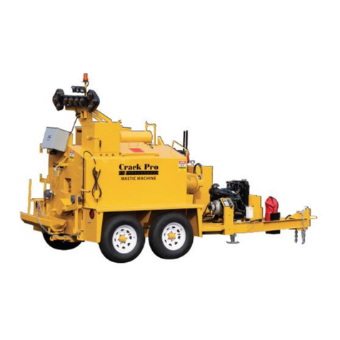
SealMaster CRACK PRO 125 User manual


S:\Engineering\13-Operator Manuals\Current\CRACKPRO_HEATEDHOSE_V2.0_OCT2019.docx
CRACK PRO HEATED HOSE
Owner’s Manual
Version 2.0
Issue Date: Oct. 2019
Effective Date: May 2019
Version
Date
Changes
Approval
1.0
Original Issue
2.0
8/19
New Format and Updates
DS

3
Table of Contents
CORRESPONDENCE .......................................................................................................................................................5
SealMaster® LIMITED WARRANTY ...............................................................................................................................6
INTRODUCTION .............................................................................................................................................................7
CRACK PRO® HEATED HOSE ......................................................................................................................................7
SAFETY PRECAUTIONS AND CAUTIONS........................................................................................................................8
PRECAUTIONS............................................................................................................................................................8
CAUTIONS..................................................................................................................................................................8
FIRST AID ...................................................................................................................................................................9
CHECK IT OUT ..........................................................................................................................................................10
KNOW YOUR MACHINE ...........................................................................................................................................10
FIRE PREVENTION....................................................................................................................................................10
DRESS FOR SAFETY ..................................................................................................................................................11
LEARN TO BE SAFE...................................................................................................................................................11
WALK AROUND INSPECTION ...................................................................................................................................12
TRAFFIC CONTROL ...................................................................................................................................................12
PRE-OPERATION INSTRUCTIONS ................................................................................................................................13
CHECK LIST...............................................................................................................................................................13
CAUTIONS................................................................................................................................................................14
CLOTHING................................................................................................................................................................14
THINGS TO KNOW ...................................................................................................................................................15
FLUID SPECIFICATIONS ............................................................................................................................................16
SERVICE TIP FOR ENGINE START PUSHBUTTON ......................................................................................................18
A. ENGINE START-UP...........................................................................................................................................18
B. ENGINE SHUT DOWN ......................................................................................................................................18
MACHINE MAINTENANCE...........................................................................................................................................19
TROUBLE SHOOTING GUIDE....................................................................................................................................19
MAINTENANCE SCHEDULE ......................................................................................................................................21
OPERATING INSTRUCTIONS - DIESEL FUEL BURNER ..................................................................................................30
CHECK LIST...............................................................................................................................................................30
STARTING THE ENGINE............................................................................................................................................31
THE TEMPERATURE CONTROL ................................................................................................................................32
ADDING MATERIAL..................................................................................................................................................33
MATERIAL TEMPERATURE.......................................................................................................................................33
AUTOMATIC SAFETY INTERLOCKS ...........................................................................................................................34
APPLICATION OF MATERIAL ....................................................................................................................................35
SETTING TEMPERATURE CONTROL .........................................................................................................................36

4
POURING MATERIAL................................................................................................................................................37
BURNER INFORMATION CHART ..............................................................................................................................38
WIRING DIAGRAMS ....................................................................................................................................................39
TEMPERATURE CONTROL BOX ................................................................................................................................39
HEATED HOSE MAIN CONNECTOR J1 AND HEATED HOSE J2 ..................................................................................40
ELECTRIC BRAKES AND RUNNING LIGHTS ...............................................................................................................41
MACHINE PICTURES AND PARTS LIST.........................................................................................................................42
PARTS LIST PICTURE-1 .............................................................................................................................................43
PARTS LIST PICTURE-2 .............................................................................................................................................45
PARTS LIST PICTURE-3 .............................................................................................................................................47
PARTS LIST PICTURE-4 .............................................................................................................................................50
PARTS LIST PICTURE-5 .............................................................................................................................................52
PARTS LIST PICTURE-6 .............................................................................................................................................54
PARTS LIST FOR TEMPERATURE CONTROL BOX.........................................................................................................55
PARTS LIST PICTURE-7 .............................................................................................................................................55
PARTS LIST PICTURE-8 .............................................................................................................................................56
WIRELESS WAND CONTROL BOX OPTIONAL..............................................................................................................57
PARTS LIST PICTURE-9 .............................................................................................................................................57
PARTS LIST FOR DIESEL BURNER .............................................................................................................................59
PARTS LIST FOR AIR COMPRESSOR..........................................................................................................................60
PARTS LIST FOR ROPER 2” PUMP ............................................................................................................................61
DIESEL ENGINE PARTS LIST .........................................................................................................................................63
PARTS LIST FOR 1505 DIESEL ENGINE .....................................................................................................................63
PARTS LIST FOR 902 DIESEL ENGINE .......................................................................................................................64
PARTS LIST FOR 602 DIESEL ENGINE .......................................................................................................................65
OPERATING INSTRUCTIONS –DOUBLE PUMPER .......................................................................................................66
TEMPERATURE CONTROL........................................................................................................................................66
WIRING DIAGRAM ...................................................................................................................................................68
HEATED HOSE MAIN CONNECTOR J1 AND HEATED HOSE (J2-TIMES 2) .................................................................69
MACHINE PICTURES AND PARTS LIST DOUBLE PUMPER ...........................................................................................70
PARTS LIST PICTURE-10 ...........................................................................................................................................70
PARTS LIST PICTURE-11 ...........................................................................................................................................72
PARTS LIST PICTURE-12 ...........................................................................................................................................73
RECOMMENDED SPARE PARTS LIST ...........................................................................................................................74
LIST FOR: DIESEL ENGINE ........................................................................................................................................74
LIST FOR: CRACK PRO HEATED HOSE.......................................................................................................................74

5
ThorWorks Industries, Inc.
Purchased by __________________________ Model NO. _______________________
Company Name _______________________ Serial NO. _______________________
Address ________________________________ Acceptance Date ________________
City _____________ State______ Zip _______
CORRESPONDENCE
All Correspondence regarding this equipment, as well as general correspondence should be addressed to:
ThorWorks Industries, Inc.
PO Box 2277
Sandusky, OH 44870
In referring to the equipment, kindly state the Model Number, Serial Number and any part number involved
`

6
SealMaster® LIMITED WARRANTY
SealMaster warrants that its products are of quality material and workmanship. SealMaster
agrees to replace, within a period of one (1) year from date of delivery, or at its option, repair,
without charge, any part of their manufacture which proved defective. The repair or
replacement will be free of charge F.O.B. Sandusky, Ohio, proving the damaged part or parts
are returned, freight prepaid, to SealMaster and investigation show such repair or replacement
is made necessary by an inherent defect of material or workmanship.
It is hereby understood that engines, motors, pumps, or other components purchased by
SealMaster for use on its equipment are not warranted by SealMaster and are sold only with
the standard warranty of the manufacturer of that component.
SealMaster will make no allowances for repairs or alterations completed by outside sources
unless authorization is in writing and approved by an authorized SealMaster representative.
Any claims for defective material or workmanship must be made prior to the expiration of thirty
(30) days from the date failure occurs, and in all cases prior to the expiration of the warranty
period of one (1) year. It is the intent of this paragraph to limit SealMaster’s liability solely to
the cost of replacement parts, F.O.B. factory, or at the option of SealMaster to repair of the
defective part or parts. No allowances for damages, lost time, or any other claim will be
recognized.
This warranty is null and void if other than genuine SealMaster parts are used.
SealMaster is constantly striving to improve their products. Changes in design and
improvement will be made whenever the manufacturer believes the efficiency of the product
will be improved, without incurring any obligation to incorporate such improvements in any
machines which have been shipped or are in service.
In an effort to continue to improve product quality, SealMaster reserves the right to change
specifications without notice.
Any modification or alteration of this machine without prior approval of the manufacturer may
void this warranty.

7
CRACK PRO® HEATED HOSE MACHINE
APPLIES TO ALL DIESEL FUEL BURNER
INTRODUCTION
CRACK PRO® HEATED HOSE
This manual covers the oil jacketed CRACK PRO® model sizes 125, 200, 260 & 400
- gallon models.
Included also is the oil jacketed CRACK PRO® model size 260 double pumper.
Congratulations on the purchase of your new CRACK PRO® HEATED HOSE joint
sealing machine. This machine is manufactured with the commitment of quality
the CRACK PRO® is known for. It is manufactured for high speed melting of joint
sealing material and the shortest melting time for all hot pour materials.
This manual will assist you in the maintenance and operation of your joint sealing
machine for many years.

8
SAFETY PRECAUTIONS AND CAUTIONS
PRECAUTIONS
Always wear eye and ear protection, long sleeve shirt, face shield
and gloves.
Be aware of all CAUTION, WARNING, and DANGER signs on the
unit.
The high operating temperatures of your joint sealing machine
and materials require special training and maintenance of your
equipment.
Read and follow these operating instructions to every detail.
Make sure the operator is familiar with the units’ operation.
CAUTIONS
Keep hands, feet, and clothing away from moving parts.
Do not operate the machine without all guards in place.
Never fill the fuel tank with a lit burner.
WARNING! When checking oil levels, never check when HOT!
WARNING! When the burner is on DO NOT exceed 10 mph while
towing, or damage to the burner or machine may occur.

9
SAFETY PRECAUTIONS AND CAUTIONS
FIRST AID

10
SAFETY PRECAUTIONS AND CAUTIONS
CHECK IT OUT
Know what protective devices your machine is equipped with and see that
each item is securely in place and in operating condition.
For example:
1. Warning Decals
2. Guards
3. Material hose connections and protective sleeve
4. Grounding wires
KNOW YOUR MACHINE
Have all of the repairs been made that you reported? The most minor
malfunction could be the result of more serious trouble.
FIRE PREVENTION
Avoid fire hazards such as:
1. Always stop the engine when refueling, do not refuel while smoking
or when near an open flame or sparks.
2. Always wipe up any spills immediately.
3. Batteries produce explosive gases, keep open flame or sparks away.
4. Remove all trash or debris from the machine, make sure that oily
rags or other flammable materials are not stored in or on the
machine.
5. Check for fuel, engine oil, and hydraulic leaks, replace worn or
damaged hoses.
6. Inspect electrical wiring for worn or damaged insulation, replace as
needed.
WARNING: LETHAL FUMES!
Engine and burner exhaust gases contain carbon monoxide. Carbon
monoxide is odorless, colorless and can cause death if inhaled. Avoid
inhaling exhaust fumes, and never run the burner or engine in an enclosed
building or confined area. Symptoms of poisoning are:
1. Dizziness
2. Headache
3. Weakness, Sleepiness and Vomiting

11
SAFETY PRECAUTIONS AND CAUTIONS
DRESS FOR SAFETY
When operating your Crack Pro equipment always wear the following:
1. Long pants
2. Long sleeved shirt
3. Heat resistant gloves
4. Eye protection (face shield is preferred)
5. Work shoes
6. Safety Vest
WARNING: MOVING PARTS
Keep hands, feet, hair, and clothing away from all moving parts.
Never operate the machine with covers, shrouds, or guards removed.
Do not wear loose or dangling clothing or jewelry near the
equipment. It could become caught and possibly cause serious injury
or death.
LEARN TO BE SAFE
1. STUDY THE OPERATORS MANUAL and other pertinent information
furnished with the equipment. Learn your machines operating and
maintenance characteristics, capacities, and limitations.
2. Learn the location and function of all controls, indicators, and
warning devices.
3. Be familiar with the safety devices on your machine.
4. Learn to recognize the machines warning and safety signals, they will
alert you to conditions that may make it hazardous to continue
operating.
5. Carefully read and follow all safety signs and instructions on the
machine.
6. Keep safety signs and instructions in good condition, replace missing
or damaged signs immediately.
7. Do not open the tank lid and put your head directly over the opening.
Besides not being good to breathe, there may be enough oxygen
introduced into the tank to cause the sealant to self-ignite.

12
SAFETY PRECAUTIONS AND CAUTIONS
WALK AROUND INSPECTION
Before each day, walk around the machine and inspect for leaks, loose or
missing parts, damaged parts, or parts out of adjustment. Perform all
recommended daily maintenance.
TRAFFIC CONTROL
Proper traffic control is your responsibility. Never place sealant in an
uncontrolled area. Protect vehicles and pedestrians from the workplace
until the sealant has thoroughly cooled (100°F or the pavement surface
temperature)
REMEMBER:
ONLY YOU CAN PREVENT INJURY TO YOURSELF AND OTHERS!
SAFETY IS YOUR RESPONSIBILITY!

13
CRACK PRO® HEATED HOSE MACHINE
PRE-OPERATION INSTRUCTIONS
CHECK LIST
THE ENTIRE UNIT SHOULD BE CHECKED
Even though your Crack Pro joint sealing machine is ready for
operation when you receive it, certain items should be checked before
putting it to use.
If you have any questions on the operation of this machine discontinue
operation of the machine and call the factory immediately.
(419-626-4375)
Most important items to check are listed below:
Check nuts, set screws, and bolts to assure that no loosening
occurred doing shipment.
Check tightness of all heat transfer oil HTO hoses. (steel braided
hoses)
Check to be sure the HTO vent pipe is clear and open for venting,
located on the HTO expansion tank.
Check wheel lug nuts after first 100 miles of travel.
Never operate machine unattended.
Never exceed heat transfer oil limit of 500°F when operating.
Do not expose material hose to direct flame.
Close tank lid before transporting.

14
CRACK PRO® HEATED HOSE MACHINE
PRE-OPERATION INSTRUCTIONS
CAUTIONS
Caution should be used when loading blocks to prevent possible splash
of hot material. Set material block (one at a time) on the lid. Close lid
allowing the block to drop into the material tank.
Do not breathe joint sealing material fumes.
Do not load more than four boxes of material into the machine
at one time.
Do not exceed 10 mph when towing with the burner on.
Do not operate the machine in the rain.
Do not pressure wash the burner area in front of the machine.
Do not work on the machine while it is in operation.
Do not work on the machine when heat transfer oil has been
heated over 90°F.
Never expose material tank to an open flame.
CLOTHING
Proper clothing should be worn at all times.
long sleeve shirt
face shield
high-temperature gloves
long pants

15
CRACK PRO® HEATED HOSE MACHINE
PRE-OPERATION INSTRUCTIONS
THINGS TO KNOW
The heated hose on this machine operates at 90 - 110 volts ac. Every
caution has been taken to ensure a safe operating the machine.
The information listed here needs to be told to anybody who uses or
works on this machine.
Never operate when conditions are wet. Allow the machine to
dry completely before using.
The digital temperature control box houses both 120 volts ac
and 12 volts dc.
While they are separated, anybody doing diagnostic testing
needs to be made aware of the dual voltages.
DO NOT MOVE THE HOSE WHEN IT IS COLD!
Doing so may kink the inner tube resulting in a hose that will be
destroyed, and will have to be replaced. It will not be covered by the
machines standard warranty.
Should the protective sleeve become cut or damaged in any way, do not use.
Electrical wires are wound around the inner hose, any exposed wires are an
electrocution hazard. Replace the hose immediately.

16
CRACK PRO® HEATED HOSE MACHINE
OPERATING INSTRUCTIONS
FLUID SPECIFICATIONS
Diesel engine crankcase oil:
The break-in oil should be changed after the first 50 hours of operation.
Oil change intervals:
Temperature Oil type Interval
Above 77°F SAE 30 or 10w-30 with filter 100 hours
Between 32°F to 77°F SAE 20 or 10w-30 with filter 100 hours
32°F or below SAE 10 or 10w-30 with filter 100 hours
Hydraulic oil:
The hydraulic system should be drained, cleaned, and refilled every
two years.
If the oil becomes contaminated at any time, flush the system
immediately. The oil filter should be changed yearly.
System capacity is 30 gallons.
Change the hydraulic oil filter after the first 20 hours of operation.
The factory installed oil meets the following specifications:
Grade 68
Viscosity @ 100°F SUS 306
Approximate SAE grade 20W
Factory installed oil: COMMERCIAL AW Hydraulic Oil
See enclosed MSDS

17
CRACK PRO® HEATED HOSE MACHINE
OPERATING INSTRUCTIONS
FLUID SPECIFICATIONS
Heat Transfer Oil:
Heat transfer oil is specially formulated to withstand high temperature and many
heating and cooling cycles. The normal life cycle is one to two years, depending
on how much the machine is used.
Never leave the oil in the machine for more than two years.
The procedure for checking the oil level is to ALWAYS CHECK IT COLD.
Located on the expansion tank is an oil level dip stick, there is a mark on the dip
stick to designate the full point. When adding oil, it is necessary to remove the oil
thermometer from the top rear curbside corner. Install a funnel here, and check
with the dip stick.
Heat Transfer Oil Gallons per Tank:
Tank Size
Gallons
125
25
200
28
260
30
400
45
DO NOT OVERFILL, OVER FILLING WILL CAUSE OIL TO COME OUT THE OVERFLOW
VENT PIPE AND ONTO THE GROUND WHEN THE MACHINE IS BEING HEATED
Oil coming out of the vent pipe means one of two reasons, overfilling or moisture
is present in the oil jacket.
Immediately shut off the burner if this happens. Let the machine cool
completely.
Water in the oil is extremely dangerous. Never heat the machine if water is
present. Drain and replace.
The factory installed oil meets the following specifications:
Name Industrial turbine oil
Flashpoint >390°F
Auto-ignition temp. >500°F
Factory installed oil: Turbine XL 68 See enclosed MSDS

18
CRACK PRO® HEATED HOSE MACHINE
OPERATING INSTRUCTIONS BEFORE 2017
SERVICE TIP FOR ENGINE START PUSHBUTTON
A. ENGINE START-UP
Red pushbutton on panel must be held in the depressed position while starting engine
until running oil pressure is established to open SWICHGAGE contacts. NBMNBNB
(1) 518-APH pushbutton should remain in the depressed position during normal running.
If pushbutton fails to remain in the depressed position:
(A) Visually check wiring for loose connections, frayed wiring, etc., on all terminals and
switch loop circuit.
(B) Check 14amp fuse connected to “B” terminal.
(C) Check for good ground on “G” terminal.
(D) Disconnect switch loop circuit from SW1 and SW2 terminals. Place temporary jumper
between SW1 and SW2 and restart engine. If pushbutton stays in with engine running, 518-
APH switch is not the problem. This indicates either an open circuit, unwanted ground, or
too high resistance in switch loop circuit wiring, between SW1 and SW2.
(E) Continuity checks power removed from “B” terminal.
(1) With ohmmeter or continuity light, check for good continuity through switch
loop circuit. If good continuity is indicated, proceed to step (2).
(2) Unwanted ground in loop circuit. With SWICHGAGE contact adjusted away
from pointer, check continuity between one end of loop circuit and ground. Good continuity”
indicates an unwanted ground in loop circuit such as a terminal rotated against mounting panel.
Remove ground, restore loop circuit connections to SW1 and SW2, power to (B), restart engine.
(3) Too high resistance in switch wiring
With ohmmeter, check resistance between one end of the loop circuit to the
other. Resistance should exceed 25 ohms. If resistance is too high, recheck
for loose connections in loop circuit. Otherwise select larger size wire for
loop circuit.
B. ENGINE SHUT DOWN
(A) Engine fails to shut down when contacts close on one wire to ground SWICHGAGE controls.
(1) With engine running, jumper SW1 to “G” terminal. If switch trips and engine
shuts down, trouble is failure of SWICHGAGE contacts to make contact or lack of good case
ground on SWICHGAGE. Adjust contacts back and forth to give a wiping and cleaning action on
contacts. Check switch mounting for good ground.

19
CRACK PRO® HEATED HOSE MACHINE
MACHINE MAINTENANCE
TROUBLE SHOOTING GUIDE
See oil burner trouble shooting guide for step by step instructions
PROBLEM
MATERIAL PUMP
LEAKING
HOSE
NO PRESSURE
DIESEL BURNER
HAS LOW OPERATING PSI
BURNER
DOES NOT LIGHT
POSSIBLE CAUSES/SOLUTIONS
LEAKING AROUND SHAFT / TIGHTEN & REPLACE PACKING
PUMP GEARS WORN / REPLACE PUMP GEARS
HYDRAULIC MOTOR WORN / REPLACE HYDRAULIC MOTOR
PUMP SHAFT NOT TURNING / CHECK WIRING - FUSE
PUMP WORN / CHECK AND REPLACE
FUEL LINE PLUGGED / CLEAN OR REPLACE
PUMP COUPLER BROKEN / REPLACE COUPLER
BURNER MOTOR WORN / REPLACE MOTOR
ELECTRODES WORN AT TIPS / REPLACE ELECTRODES
ELECTRODES SPACING INCORRECT/ RESET SPACING
CAD CELL DIRTY / CLEAN GLASS LENS
WATER IN FUEL / REPLACE FUEL & FILTER
BURNER IN LOCKOUT / REMOVE NEGATIVE CABLE & REATTACH
FUEL NOZZLE PLUGGED / REFER TO OWNER’S MANUAL
AIR SHUTTER MOVED / REFER TO OWNER’S MANUAL
FUEL FILTER PLUGGED / CLEAN AS NEEDED
AIR IN PUMP / OPEN BLEEDER
TRANSFORMER WORN / REPLACE TRANSFORMER
PRIMARY CONTROL FAILED / REPLACE PRIMARY CONTROL
FUEL SOLENOID FAILED / REPLACE SOLENOID
NO POWER FROM CONTROLLER / TRACE WIRES
HI-TEMP LIGHT IS ON / PUSH RESET

20
CRACK PRO® HEATED HOSE MACHINE
MACHINE MAINTENANCE
TROUBLE SHOOTING GUIDE
PROBLEM
ENGINE
ISSUES
(HTO) HEATED TRANSFER OIL
COMING OUT OF VENT PIPE
(HTO) HEATED TRANSFER OIL
NOT CIRCULATING
CP-400 ONLY
HYDRAULIC SYSTEM
NOT WORKING
AGITATOR
DOES NOT ROTATE
POSSIBLE CAUSES/SOLUTIONS
OIL SPECIFICATIONS / REFER TO OWNER’S MANUAL
OPERATING INSTRUCTIONS / REFER TO OWNER’S MANUAL
DEAD BATTERY / REPLACE BATTERY
LOW ON FUEL / FILL FUEL TANK
PLUGGED FUEL LINE / CLEAN FUEL SYSTEM
PLUGGED FILTER / CHANGE FILTER
OVER HEATED HTO / CHECK TEMPERATURE CONTROL
MOISTURE IN HTO TANK / DRAIN AND REPLACE
HTO PAST OPERATING LIFE / DRAIN AND REPLACE
BROKEN DRIVE COUPLER / REPLACE COUPLER
Y-STRAINER PLUGGED / DRAIN AND REPLACE
HTO LINE VALVES CLOSED / OPEN VALVES
HTO LINE KINKED / REPLACE LINE
LOW ON HTO / CHECK LEVEL AND FILL
HTO PUMP WORN / REPLACE PUMP
DRIVE MOTOR WORN / REPLACE DRIVE MOTOR
LOW OIL LEVEL / CHECK LEVEL AND FILL
HYDRAULIC PUMP WORN / REPLACE PUMP
FILTER PLUGGED / REPLACE FILTER
TANK VALVE CLOSED / OPEN VALVE
KINKED HOSE / REPLACE HOSE
NO POWER AT 12V VDC COIL / CHECK WIRING & FUSE
BROKEN DRIVE COUPLER / REPLACE COUPLER
BROKEN DRIVE MOTOR / REPLACE MOTOR
NOT WORKING LID SWITCH / CHECK LID SWITCH
HYDRAULIC CARTRIDGE / REPAIR OR REPLACE
This manual suits for next models
3
Table of contents
Other SealMaster Construction Equipment manuals


